US5567508A - Rolling bearing with surface hardened layer - Google Patents

Rolling bearing with surface hardened layer Download PDF

Info

Publication number
US5567508A
US5567508A US08/515,042 US51504295A US5567508A US 5567508 A US5567508 A US 5567508A US 51504295 A US51504295 A US 51504295A US 5567508 A US5567508 A US 5567508A
Authority
US
United States
Prior art keywords
depth
hardened layer
rolling
life
point
Prior art date
Legal status (The legal status is an assumption and is not a legal conclusion. Google has not performed a legal analysis and makes no representation as to the accuracy of the status listed.)
Expired - Lifetime
Application number
US08/515,042
Inventor
Yasuo Murakami
Current Assignee (The listed assignees may be inaccurate. Google has not performed a legal analysis and makes no representation or warranty as to the accuracy of the list.)
NSK Ltd
Yazaki Corp
Original Assignee
NSK Ltd
Priority date (The priority date is an assumption and is not a legal conclusion. Google has not performed a legal analysis and makes no representation as to the accuracy of the date listed.)
Filing date
Publication date
Application filed by NSK Ltd filed Critical NSK Ltd
Assigned to YAZAKI CORPORATION reassignment YAZAKI CORPORATION ASSIGNMENT OF ASSIGNORS INTEREST (SEE DOCUMENT FOR DETAILS). Assignors: MUAKAMI, YASUO
Assigned to NSK LTD reassignment NSK LTD RECORD TO CORRECT ASSIGNOR AND ASSIGNEE PREVIOUSLY RECORDED AT REEL 7637 FRAME 020. (SEE RECORD FOR DETAILS.) Assignors: MURAKAMI, YASUO
Application granted granted Critical
Publication of US5567508A publication Critical patent/US5567508A/en
Anticipated expiration legal-status Critical
Expired - Lifetime legal-status Critical Current

Links

Images

Classifications

    • CCHEMISTRY; METALLURGY
    • C21METALLURGY OF IRON
    • C21DMODIFYING THE PHYSICAL STRUCTURE OF FERROUS METALS; GENERAL DEVICES FOR HEAT TREATMENT OF FERROUS OR NON-FERROUS METALS OR ALLOYS; MAKING METAL MALLEABLE, e.g. BY DECARBURISATION OR TEMPERING
    • C21D9/00Heat treatment, e.g. annealing, hardening, quenching or tempering, adapted for particular articles; Furnaces therefor
    • C21D9/36Heat treatment, e.g. annealing, hardening, quenching or tempering, adapted for particular articles; Furnaces therefor for balls; for rollers
    • CCHEMISTRY; METALLURGY
    • C21METALLURGY OF IRON
    • C21DMODIFYING THE PHYSICAL STRUCTURE OF FERROUS METALS; GENERAL DEVICES FOR HEAT TREATMENT OF FERROUS OR NON-FERROUS METALS OR ALLOYS; MAKING METAL MALLEABLE, e.g. BY DECARBURISATION OR TEMPERING
    • C21D9/00Heat treatment, e.g. annealing, hardening, quenching or tempering, adapted for particular articles; Furnaces therefor
    • C21D9/40Heat treatment, e.g. annealing, hardening, quenching or tempering, adapted for particular articles; Furnaces therefor for rings; for bearing races
    • CCHEMISTRY; METALLURGY
    • C23COATING METALLIC MATERIAL; COATING MATERIAL WITH METALLIC MATERIAL; CHEMICAL SURFACE TREATMENT; DIFFUSION TREATMENT OF METALLIC MATERIAL; COATING BY VACUUM EVAPORATION, BY SPUTTERING, BY ION IMPLANTATION OR BY CHEMICAL VAPOUR DEPOSITION, IN GENERAL; INHIBITING CORROSION OF METALLIC MATERIAL OR INCRUSTATION IN GENERAL
    • C23CCOATING METALLIC MATERIAL; COATING MATERIAL WITH METALLIC MATERIAL; SURFACE TREATMENT OF METALLIC MATERIAL BY DIFFUSION INTO THE SURFACE, BY CHEMICAL CONVERSION OR SUBSTITUTION; COATING BY VACUUM EVAPORATION, BY SPUTTERING, BY ION IMPLANTATION OR BY CHEMICAL VAPOUR DEPOSITION, IN GENERAL
    • C23C8/00Solid state diffusion of only non-metal elements into metallic material surfaces; Chemical surface treatment of metallic material by reaction of the surface with a reactive gas, leaving reaction products of surface material in the coating, e.g. conversion coatings, passivation of metals
    • C23C8/06Solid state diffusion of only non-metal elements into metallic material surfaces; Chemical surface treatment of metallic material by reaction of the surface with a reactive gas, leaving reaction products of surface material in the coating, e.g. conversion coatings, passivation of metals using gases
    • C23C8/08Solid state diffusion of only non-metal elements into metallic material surfaces; Chemical surface treatment of metallic material by reaction of the surface with a reactive gas, leaving reaction products of surface material in the coating, e.g. conversion coatings, passivation of metals using gases only one element being applied
    • C23C8/20Carburising
    • C23C8/22Carburising of ferrous surfaces
    • CCHEMISTRY; METALLURGY
    • C23COATING METALLIC MATERIAL; COATING MATERIAL WITH METALLIC MATERIAL; CHEMICAL SURFACE TREATMENT; DIFFUSION TREATMENT OF METALLIC MATERIAL; COATING BY VACUUM EVAPORATION, BY SPUTTERING, BY ION IMPLANTATION OR BY CHEMICAL VAPOUR DEPOSITION, IN GENERAL; INHIBITING CORROSION OF METALLIC MATERIAL OR INCRUSTATION IN GENERAL
    • C23CCOATING METALLIC MATERIAL; COATING MATERIAL WITH METALLIC MATERIAL; SURFACE TREATMENT OF METALLIC MATERIAL BY DIFFUSION INTO THE SURFACE, BY CHEMICAL CONVERSION OR SUBSTITUTION; COATING BY VACUUM EVAPORATION, BY SPUTTERING, BY ION IMPLANTATION OR BY CHEMICAL VAPOUR DEPOSITION, IN GENERAL
    • C23C8/00Solid state diffusion of only non-metal elements into metallic material surfaces; Chemical surface treatment of metallic material by reaction of the surface with a reactive gas, leaving reaction products of surface material in the coating, e.g. conversion coatings, passivation of metals
    • C23C8/06Solid state diffusion of only non-metal elements into metallic material surfaces; Chemical surface treatment of metallic material by reaction of the surface with a reactive gas, leaving reaction products of surface material in the coating, e.g. conversion coatings, passivation of metals using gases
    • C23C8/28Solid state diffusion of only non-metal elements into metallic material surfaces; Chemical surface treatment of metallic material by reaction of the surface with a reactive gas, leaving reaction products of surface material in the coating, e.g. conversion coatings, passivation of metals using gases more than one element being applied in one step
    • C23C8/30Carbo-nitriding
    • C23C8/32Carbo-nitriding of ferrous surfaces
    • FMECHANICAL ENGINEERING; LIGHTING; HEATING; WEAPONS; BLASTING
    • F16ENGINEERING ELEMENTS AND UNITS; GENERAL MEASURES FOR PRODUCING AND MAINTAINING EFFECTIVE FUNCTIONING OF MACHINES OR INSTALLATIONS; THERMAL INSULATION IN GENERAL
    • F16CSHAFTS; FLEXIBLE SHAFTS; ELEMENTS OR CRANKSHAFT MECHANISMS; ROTARY BODIES OTHER THAN GEARING ELEMENTS; BEARINGS
    • F16C33/00Parts of bearings; Special methods for making bearings or parts thereof
    • F16C33/30Parts of ball or roller bearings
    • F16C33/58Raceways; Race rings
    • F16C33/62Selection of substances
    • FMECHANICAL ENGINEERING; LIGHTING; HEATING; WEAPONS; BLASTING
    • F16ENGINEERING ELEMENTS AND UNITS; GENERAL MEASURES FOR PRODUCING AND MAINTAINING EFFECTIVE FUNCTIONING OF MACHINES OR INSTALLATIONS; THERMAL INSULATION IN GENERAL
    • F16CSHAFTS; FLEXIBLE SHAFTS; ELEMENTS OR CRANKSHAFT MECHANISMS; ROTARY BODIES OTHER THAN GEARING ELEMENTS; BEARINGS
    • F16C33/00Parts of bearings; Special methods for making bearings or parts thereof
    • F16C33/30Parts of ball or roller bearings
    • F16C33/58Raceways; Race rings
    • F16C33/64Special methods of manufacture
    • YGENERAL TAGGING OF NEW TECHNOLOGICAL DEVELOPMENTS; GENERAL TAGGING OF CROSS-SECTIONAL TECHNOLOGIES SPANNING OVER SEVERAL SECTIONS OF THE IPC; TECHNICAL SUBJECTS COVERED BY FORMER USPC CROSS-REFERENCE ART COLLECTIONS [XRACs] AND DIGESTS
    • Y10TECHNICAL SUBJECTS COVERED BY FORMER USPC
    • Y10STECHNICAL SUBJECTS COVERED BY FORMER USPC CROSS-REFERENCE ART COLLECTIONS [XRACs] AND DIGESTS
    • Y10S384/00Bearings
    • Y10S384/90Cooling or heating
    • Y10S384/912Metallic
    • YGENERAL TAGGING OF NEW TECHNOLOGICAL DEVELOPMENTS; GENERAL TAGGING OF CROSS-SECTIONAL TECHNOLOGIES SPANNING OVER SEVERAL SECTIONS OF THE IPC; TECHNICAL SUBJECTS COVERED BY FORMER USPC CROSS-REFERENCE ART COLLECTIONS [XRACs] AND DIGESTS
    • Y10TECHNICAL SUBJECTS COVERED BY FORMER USPC
    • Y10TTECHNICAL SUBJECTS COVERED BY FORMER US CLASSIFICATION
    • Y10T428/00Stock material or miscellaneous articles
    • Y10T428/24Structurally defined web or sheet [e.g., overall dimension, etc.]
    • Y10T428/24942Structurally defined web or sheet [e.g., overall dimension, etc.] including components having same physical characteristic in differing degree
    • Y10T428/24983Hardness

Definitions

  • the present invention relates to rolling bearings for use in vehicles, agricultural machines, construction machines, steel making machines, and the like. More particularly, the present invention relates to rolling bearings having a surface hardened layer with high impact resistance and long service life so that it is suitable for use in transmissions and engines.
  • Rolling bearings are used under severe conditions in which they are subjected to repeated shearing stress under high contact pressure.
  • a high-carbon chromium bearing steel (SUJ 2) has generally been used as a bearing material.
  • the steel is hardened and tempered to provide the Rockwell hardness of H R C 58 to 64.
  • Case hardening steels have also been used to extend the life of bearings.
  • low carbon case hardening steels such as SCR 420H, SCM 420H, SAE 8620H, SAE 4320H and the like, which have the superior hardenability, are carburized or carbonitrided, followed by hardening and tempering to produce inner and outer races and rolling elements that have the surface hardness of H R C 58 to 64 and the core hardness of H R C 30 to 48.
  • the required service life has been secured by the above heat treatments.
  • a surface hardened layer that is too thick not only increases the cost of heat treatments because an elongated time is required for carburization or carbonitriding but also deteriorates the superior impact strength property which is inherent from the surface hardening treatment.
  • the present invention has an object of providing a rolling bearing having a surface hardened layer that is capable of improving both the rolling life and the impact strength.
  • This object of the present invention can be attained by a rolling bearing with components including an inner race, an outer race and a plurality of rolling elements, one of the components being carburized or carbonitrided to form a hardened layer on a surface thereof, in which a depth of the hardened layer is 0.025 to 0.045 times an average diameter of the rolling elements at a point Zo and a depth ratio (Zo/Yo) of the point Zo to a point Yo is less than or equal to 0.8.
  • FIG. 1 is a diagram illustrating the contact pressure of contact acting between two cylinders, and the width of their contact;
  • FIG. 2 is a graph showing the distribution of contact stresses
  • FIG. 3 is a perspective view of a test specimen for use in impact tests
  • FIG. 4 is a sketch showing diagrammatically the method of the impact tests
  • FIG. 5 is a diagrammatic representation of a medium-size box life tester
  • FIG. 6 is a graph showing the relationship between impact absorbing energy and the depth of a hardened layer.
  • FIG. 7 is a graph showing the relationship between L 10 life and the depth of a hardened layer.
  • FIG. 2 is a graph showing how the stress distribution changes in the directions of depth Z below the contact surface in the above case.
  • the shearing stress ⁇ st in vicinity of the contact point is given by ( ⁇ x - ⁇ z )/2, where ⁇ x and ⁇ z are the main stresses in the directions of x and z axes, respectively.
  • ⁇ st assumes a maximum value at a certain depth of (Zst) max directly below the center of the contact point.
  • the maximum shearing stress ( ⁇ st ) max is 0.301 p max and the value of (Zst) max which is the depth at ( ⁇ st ) max is 0.786 b.
  • a basic static load rating is specified as a measure for a maximum load Q max which can be accepted by the rolling bearing in the stationary state (JIS B 1519).
  • the maximum contact pressure p max is about 400 kgf/mm 2 . In practice, such a high contact pressure cannot be applied. At most, p max is 300 kgf/mm 2 .
  • the present inventors conducted further studies on the relationship between the depth of the hardened layer and the impact strength.
  • the inventors prepared samples which had various levels of the depth of the hardened layer and its hardness to evaluate the impact strength and the life of each sample. Based on the test results, the inventors specified a hardness curve that is optimal for practical rolling bearings to thereby to accomplish the present invention.
  • the present invention specifies the depth of the hardened layer to be 0.025 to 0.045 times the average diameter of rolling elements at the point Zo. The reason is because if the lower limit 0.025 is not reached, the hardened layer is too shallow to secure the required life under heavy loads, on the other hand, if the upper limit 0.045 is exceeded, the impact absorbing energy reduces to the level of bearing steels.
  • the present invention specifies the value of Zo/Yo to be less than 0.8. This is because experiments have substantiated that if Zo/Yo is 0.8 or more, the slope of the hardness curve showing the change in the hardness of the hardened layer in the direction of its depth becomes so steep that the life of the rolling bearing is shorter than the calculated value.
  • the samples used in the examples were conical roller bearings identified with a designation of 30306D (average roller diameter of 9 mm).
  • SCr 420 and SCr 440 (case hardening steels) were used not only for inventive examples according the present invention but SUJ 2 (bearing steel) was also used for comparative examples. Parts made of case hardening steels were subjected to carburizing (or carbonitriding).
  • Each sample was adjusted to have a Rockwell surface hardness H R C 62.
  • the depth (mm) of the point Zo where the Vickers hardness was Hv 653 (equivalent to H R C 58) and the depth (mm) of the point Yo where the hardness was Hv 550 (H R C 52.4) were measured to determine their respective ratios Zo/Da and Yo/Da to the average diameter (Da in mm) of rolling elements.
  • the ratio of Zo to Yo (Zo/Yo) was also determined.
  • impact tests were conducted on each sample to investigate the relationship between the depth of the hardened layer and its impact strength.
  • the impact absorption energy was determined for each sample to evaluate its impact strength.
  • Life tests were also conducted on each sample to determine its L 10 life, so that its durability was evaluated.
  • test specimen S was mounted on the support 10 of a Charpy impact tester as shown in FIG. 4.
  • a medium-size box tester (as specified on page 14 of SAE Paper 940728) was employed to perform the life tests under clean lubricating conditions. As shown in FIG. 5, the medium-size box tester mounted samples 20 of bearings under an axial load Pa, and a radial load Pr applied through a support bearing 21. Further, a lubricant was agitated by air agitators 22. The calculated life was 28 hours.
  • the other test conditions were:
  • Thrust load Fa 700 kgf
  • Rotational speed N 4,000 rpm.
  • the relationship between impact absorbing energy and the depth of the hardened layer is graphically shown in FIG. 6.
  • the vertical axis of the graph plots the impact absorbing energy (kg ⁇ m) and the horizontal axis plots both the depth (mm) to the point Zo where the Vickers hardness was Hv 653 (equivalent to H R C of 58) and the ratio Zo/Da of Zo to the average diameter Da (mm) of the rollers as rolling elements.
  • L 10 life and the depth of the hardened layer is graphically shown in FIG. 7.
  • the vertical axis of the graph plots the life (hour) and the horizontal axis plots both the depth (mm) to the point Zo where the Vickers hardness was Hv 653 (equivalent to H R C 58) and the ratio Zo/Da of Zo to the average diameter Da (mm) of the rollers.
  • the rolling bearing of the present invention has any one of the components (i.e., an inner race, an outer race and a plurality of rolling elements) carburized or carbonitrided to form a surface hardened layer, characterized in that the depth of the hardened layer is 0.025 to 0.045 times the average diameter of the rolling elements at point Zo and that the depth ratio of the point Zo to the point Yo (Zo/Yo) is less than or equal to 0.8.
  • This is effective in securing against not only the shortening of the bearing's life under heavy loads due to the formation of a hardened layer that is too shallow but also the drop of impact absorbing energy to the level of bearing steels due to the formation of a hardened layer that is too deep.
  • the slope of the hardness curve representing the hardness of the hardened layer fin the direction of its depth is not so steep that there is no possibility that the life of the rolling bearing becomes shorter than the calculated value.
  • the rolling bearing of the present invention is improved in both the rolling life and the impact strength.

Abstract

One of components of a rolling bearing which includes an inner race, an outer race and a plurality of rolling elements is carburized or a carbonitrided to form a surface hardened layer, and the depth of the hardened layer is 0.025 to 0.045 times the average diameter of the rolling elements at a point Zo and the depth ratio (Zo/Yo) of the point Zo to a point Yo is less than or equal to 0.8. The rolling bearing having the surface hardened layer is capable of improving both the rolling life and the impact strength.

Description

BACKGROUND OF THE INVENTION
The present invention relates to rolling bearings for use in vehicles, agricultural machines, construction machines, steel making machines, and the like. More particularly, the present invention relates to rolling bearings having a surface hardened layer with high impact resistance and long service life so that it is suitable for use in transmissions and engines.
Rolling bearings are used under severe conditions in which they are subjected to repeated shearing stress under high contact pressure. In order to withstand the applied shearing stress to thereby secure the necessary rolling fatigue life (hereinafter also referred to simply as "rolling life" or "life"), a high-carbon chromium bearing steel (SUJ 2) has generally been used as a bearing material. The steel is hardened and tempered to provide the Rockwell hardness of HR C 58 to 64.
Case hardening steels have also been used to extend the life of bearings. In order to set a hardness curve in accordance with the distribution of internal shearing stresses due to a contact pressure, low carbon case hardening steels such as SCR 420H, SCM 420H, SAE 8620H, SAE 4320H and the like, which have the superior hardenability, are carburized or carbonitrided, followed by hardening and tempering to produce inner and outer races and rolling elements that have the surface hardness of HR C 58 to 64 and the core hardness of HR C 30 to 48. Thus, the required service life has been secured by the above heat treatments.
However, no definite criteria have been set for determining the depth of a hardened layer that is appropriate for rolling bearings. For example, Unexamined Japanese Patent Publication No. Sho. 62-132031 has referred to the advances of the steel making technology in relation to the depth of the surface hardened layer in raceway rings and rolling elements of a rolling bearing. That is, it shows that the relationship between the depth of carburization in case hardening steels and service life which has drastically changed in the past ten years. Stated more specifically, the results of experiments conducted on case hardening steels in the 1970s showed that there was an optimal value for the depth of carburization and that the rolling life decreased irrespective of whether carburization was too shallow or deep. On the other hand, the results of experiments conducted on case hardening steels in the 1980s revealed that the rolling life elongated as the depth of carburization was increased. The results have been assumed to suggest the influence of non-metallic inclusions which serve as a source of stress concentration. On the basis of this assumption, Unexamined Japanese Patent Publication No. Sho. 62-132021 has proposed that the life of a rolling bearing extends by increasing the depth of the surface hardened layers in the raceway rings and the rolling elements to such a value as the depth relative to the diameter of each rolling element (depth/diameter) is 0.05 or more in the raceway rings and 0.07 or more in the rolling elements.
However, a surface hardened layer that is too thick not only increases the cost of heat treatments because an elongated time is required for carburization or carbonitriding but also deteriorates the superior impact strength property which is inherent from the surface hardening treatment.
SUMMARY OF THE INVENTION
The present invention has an object of providing a rolling bearing having a surface hardened layer that is capable of improving both the rolling life and the impact strength.
This object of the present invention can be attained by a rolling bearing with components including an inner race, an outer race and a plurality of rolling elements, one of the components being carburized or carbonitrided to form a hardened layer on a surface thereof, in which a depth of the hardened layer is 0.025 to 0.045 times an average diameter of the rolling elements at a point Zo and a depth ratio (Zo/Yo) of the point Zo to a point Yo is less than or equal to 0.8.
BRIEF DESCRIPTION OF THE DRAWINGS
In the accompanying drawings:
FIG. 1 is a diagram illustrating the contact pressure of contact acting between two cylinders, and the width of their contact;
FIG. 2 is a graph showing the distribution of contact stresses;
FIG. 3 is a perspective view of a test specimen for use in impact tests;
FIG. 4 is a sketch showing diagrammatically the method of the impact tests;
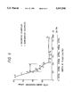
FIG. 5 is a diagrammatic representation of a medium-size box life tester;
FIG. 6 is a graph showing the relationship between impact absorbing energy and the depth of a hardened layer; and
FIG. 7 is a graph showing the relationship between L10 life and the depth of a hardened layer.
DETAILED DESCRIPTION OF THE PREFERRED EMBODIMENTS
Description will be given below in detail of an embodiment of a rolling bearing according to the present invention with reference to the accompanying drawings.
First, there are described practical and theoretical circumstances relating to the life of rolling bearings.
It is known experientially that flaking which is a factor of decreasing the life of rolling bearings often results from cracking due to rolling fatigue which occurs inside the bearing material near the rolling surface. Accordingly, it is assumed that the stress causing the flaking exists not on the surface of contact but below the surface.
Suppose that two solid members such as a raceway ring and a rolling element in a cylindrical rolling bearing contact each other to receive a load. Then, the contacting portions deform elastically to form a contact region, so that a contact pressure is produced within the contact region. If the contact region is sufficiently smaller than the solid members, Hertz contact occurs. As shown in FIG. 1, in a case where a cylinder 1 having a radius of r11 and a cylinder 2 having a radius of r12 contact each other with their axes extending parallel to each other. Then, a maximum contact pressure pmax and the width of contact 2b are given by the Hertz theory of contact stress as follows:
p.sub.max =[{E/π(1-1/m.sup.2)}·Σρ/2·Q/l.sub.a ].sup.1/2                                                 (1)
2b=[{32(1-1/m.sup.2)/πEΣρ}·Q/l.sub.a ].sup.1/2(2)
where
E: modulus of longitudinal elasticity
m: Poisson's number
Σρ: the sum of the curvatures (mm-1) of the two cylinders, Σρ=ρ1112
ρ11 : the curvature (mm-1) of cylinder 1, ρ11 =1/r11
ρ12 : the curvature (mm-1) of cylinder 2, ρ12 =2/r12
Q: the load (kgf) applied normal to the two cylinders
la : the length (mm) of contact between the two cylinders
FIG. 2 is a graph showing how the stress distribution changes in the directions of depth Z below the contact surface in the above case. The shearing stress τst in vicinity of the contact point is given by (σxz)/2, where σx and σz are the main stresses in the directions of x and z axes, respectively. Obviously from FIG. 2, τst assumes a maximum value at a certain depth of (Zst)max directly below the center of the contact point. The maximum shearing stress (τst)max is 0.301 pmax and the value of (Zst)max which is the depth at (τst)max is 0.786 b.
Dividing eq. (2) by eq. (1) gives:
2b/p.sub.max =8(1-1/m.sup.2)/E·Σρ       (3)
If the cylinder 1 shown in FIG. 1 is assumed as a roller (radius, r11 ; diameter Da=2r11) and the cylinder 2 as an inner race (radius, r12), then it can be approximated as Σρ=ρ1112 ≈1/r11 =2/Da because of r11 <r12.
When a load Q is applied to the roller (cylinder 1) and the inner race (cylinder 2) in a rolling bearing while they are in a stationary state (not rotating), local permanent deformation occurs in both members. If the deformation is unduly great, it hinders the rotation of the roller. In order to sustain the deformation within a certain limit, a basic static load rating is specified as a measure for a maximum load Qmax which can be accepted by the rolling bearing in the stationary state (JIS B 1519). According to the specification, the sum of the permanent deformations of the rolling element (cylinder 1) and the inner race (cylinder 2) that are permissible in the contact portion of the rolling bearing which is subject to the maximum stress is 0.0001 times as large as the diameter Da of the rolling element. Therefore, the maximum contact pressure pmax is about 400 kgf/mm2. In practice, such a high contact pressure cannot be applied. At most, pmax is 300 kgf/mm2.
Substituting the relationships of pmax =400 kgf/mm2 and Σρ=2/Da into eq. (3), and giving values of E=21,200 kgf/mm2 and m=10/3 for a steel, the following equation is obtained:
2b=0.0687 Da                                               (4)
Since the depth (Zst)max at the maximum shearing stress (τst)max is 0.786 b according to FIG. 2, one may substitute this value into eq. (4) to represent:
(Zst).sub.max =0.027 Da                                    (5)
Substituting pmax =400 kgf/mm2 into the above-described equation for relating the maximum shearing stress (τst)max at the depth (Zst)max to the maximum contact pressure pmax, the following value is obtained:
(τ.sub.st).sub.max =0.301×p.sub.max =120 kgf/mm.sup.2(6)
Since this value (τst)max is based on an unrealistically high contact pressure, it can safely be concluded that if a hardness curve exceeding the value is set for parts of a rolling bearing, no plastic yield occurs below the surface of the contact portion, and the hardened layer does not produce indentations or cracks causing the early flaking. The Vickers hardness (Hv) of a steel material is about three times as large as the yield stress. Theoretically, the shearing stress τst may be regarded as one half of the yield stress. Accordingly, τst is about 1/6 of Hv, indicating that the early flaking can be prevented by setting the Vickers hardness Hv to values at least six times as large as τst.
Thus, in order to satisfy the basic static load rating, a hardness at least six times as large as (τst)max=120 kgf/mm2 (see eq. (6)), namely, a Vickers hardness of at least Hv 720 (equivalent to a Rockwell hardness of at least HR C 61), is required for a layer to a depth of at least 0.027 Da below surface.
Similarly, determining a ratio z/b from the τ curve shown in FIG. 2 under Hv=6×τst and pmax =400 kgf/mm2, and calculating the relationship between the depth below surface and the required hardness Hv, it can reach the conclusion that the static load rating cannot be satisfied unless the depth Zo at Hv 653 (HR C 58) is about 0.05 Da and the depth Yo at Hv 550 (HR C 52.4) is about 0.07 Da.
Based on these findings, the present inventors conducted further studies on the relationship between the depth of the hardened layer and the impact strength. The inventors prepared samples which had various levels of the depth of the hardened layer and its hardness to evaluate the impact strength and the life of each sample. Based on the test results, the inventors specified a hardness curve that is optimal for practical rolling bearings to thereby to accomplish the present invention.
The present invention specifies the depth of the hardened layer to be 0.025 to 0.045 times the average diameter of rolling elements at the point Zo. The reason is because if the lower limit 0.025 is not reached, the hardened layer is too shallow to secure the required life under heavy loads, on the other hand, if the upper limit 0.045 is exceeded, the impact absorbing energy reduces to the level of bearing steels.
The present invention specifies the value of Zo/Yo to be less than 0.8. This is because experiments have substantiated that if Zo/Yo is 0.8 or more, the slope of the hardness curve showing the change in the hardness of the hardened layer in the direction of its depth becomes so steep that the life of the rolling bearing is shorter than the calculated value.
EXAMPLE
Examples of the present invention is further described with reference to accompanying drawings.
The samples used in the examples were conical roller bearings identified with a designation of 30306D (average roller diameter of 9 mm).
The steel species SCr 420 and SCr 440 (case hardening steels) were used not only for inventive examples according the present invention but SUJ 2 (bearing steel) was also used for comparative examples. Parts made of case hardening steels were subjected to carburizing (or carbonitriding).
Each sample was adjusted to have a Rockwell surface hardness HR C 62. The depth (mm) of the point Zo where the Vickers hardness was Hv 653 (equivalent to HR C 58) and the depth (mm) of the point Yo where the hardness was Hv 550 (HR C 52.4) were measured to determine their respective ratios Zo/Da and Yo/Da to the average diameter (Da in mm) of rolling elements. In addition, the ratio of Zo to Yo (Zo/Yo) was also determined.
Further, impact tests were conducted on each sample to investigate the relationship between the depth of the hardened layer and its impact strength. The impact absorption energy was determined for each sample to evaluate its impact strength. Life tests were also conducted on each sample to determine its L10 life, so that its durability was evaluated.
The impact tests were carried out by the following procedure.
After measuring Zo and Yo values, the inner race of each sample of the conical roller bearing identified with a designation of 30306D for inventive and comparative examples was cut out to a width of 10.0±0.05 mm to prepare a test specimen S as shown in FIG. 3. The test specimen S was mounted on the support 10 of a Charpy impact tester as shown in FIG. 4. An impact load Fs was applied to the test specimen S by a tool 11. Eight test specimens were prepared for each sample and subjected to the impact tests. The results were averaged for n=8.
The life tests were conducted by the following procedure.
A medium-size box tester (as specified on page 14 of SAE Paper 940728) was employed to perform the life tests under clean lubricating conditions. As shown in FIG. 5, the medium-size box tester mounted samples 20 of bearings under an axial load Pa, and a radial load Pr applied through a support bearing 21. Further, a lubricant was agitated by air agitators 22. The calculated life was 28 hours. The other test conditions were:
Radial load Fr=2,000 kgf;
Thrust load Fa=700 kgf; and
Rotational speed N=4,000 rpm.
Five specimens were prepared for each sample (n=5) and the test was discontinued upon the lapse of 100 hours which was 3.6 times as long as the calculated life. The condition of the life tests was far severe more than the practical level, and yet the maximum contact pressure pmax of contact between the inner race and the rollers was about 300 kgf/mm2, which was lower than the above-mentioned 400 kgf/mm2.
The results of measurements of the respective parameters and those of the tests conducted are collectively shown in Table 1.
                                  TABLE 1                                 
__________________________________________________________________________
                          Impact                                          
         Surface          absorbing                                       
Sample                                                                    
    Steel                                                                 
         hardness,        energy,                                         
No. species                                                               
         H.sub.R C                                                        
              Zo/Da                                                       
                  Yo/Da                                                   
                      Zo/Yo                                               
                          kg · m                                 
                               Life, h                                    
__________________________________________________________________________
1   SCr 420                                                               
         62.0 0.025                                                       
                  0.041                                                   
                      0.61                                                
                          0.98 ≧100                                
                                   ≧100                            
                                       ≧100                        
                                           ≧100                    
                                               ≧100                
2   "    62.1 0.031                                                       
                  0.040                                                   
                      0.78                                                
                          0.83 ≧100                                
                                   ≧100                            
                                       ≧100                        
                                           ≧100                    
                                               ≧100                
3   "    62.3 0.034                                                       
                  0.047                                                   
                      0.72                                                
                          0.62 ≧100                                
                                   ≧100                            
                                       ≧100                        
                                           ≧100                    
                                               ≧100                
4   SCr 440                                                               
         62.3 0.039                                                       
                  ∞                                                 
                      0   0.47 ≧100                                
                                   ≧100                            
                                       ≧100                        
                                           ≧100                    
                                               ≧100                
5   "    61.9 0.045                                                       
                  ∞                                                 
                      0   0.40 ≧100                                
                                   ≧100                            
                                       ≧100                        
                                           ≧100                    
                                               ≧100                
6   SCr 420                                                               
         62.0 0.010                                                       
                  0.022                                                   
                      0.45                                                
                          1.91 N.A. due to excessive vibrations           
7   "    62.1 0.017                                                       
                  0.029                                                   
                      0.59                                                
                          1.57 21  27  17  33  27                         
8   "    61.8 0.022                                                       
                  0.031                                                   
                      0.71                                                
                          1.22 45  33  51  30  27                         
9   "    62.2 0.030                                                       
                  0.037                                                   
                      0.81                                                
                          0.76 ≧100                                
                                   78  ≧100                        
                                           98  51                         
10  "    62.1 0.039                                                       
                  0.046                                                   
                      0.85                                                
                          0.54 36  77  53  ≧100                    
                                               9                          
11  SCr 440                                                               
         62.0 0.050                                                       
                  ∞                                                 
                      0   0.16 ≧100                                
                                   ≧100                            
                                       ≧100                        
                                           ≧100                    
                                               ≧100                
12  "    62.0 0.060                                                       
                  ∞                                                 
                      0   0.15 ≧100                                
                                   ≧100                            
                                       ≧100                        
                                           ≧100                    
                                               ≧100                
13  "    61.9 0.071                                                       
                  ∞                                                 
                      0   0.14 ≧100                                
                                   ≧100                            
                                       ≧100                        
                                           ≧100                    
                                               ≧100                
14  "    61.8 0.080                                                       
                  ∞                                                 
                      0   0.16 ≧100                                
                                   ≧100                            
                                       ≧100                        
                                           ≧100                    
                                               ≧100                
15  SUJ 2                                                                 
         62.1 ∞                                                     
                  ∞                                                 
                      1   0.15 58  ≧100                            
                                       ≧100                        
                                           ≧100                    
                                               96                         
__________________________________________________________________________
The relationship between impact absorbing energy and the depth of the hardened layer is graphically shown in FIG. 6. The vertical axis of the graph plots the impact absorbing energy (kg·m) and the horizontal axis plots both the depth (mm) to the point Zo where the Vickers hardness was Hv 653 (equivalent to HR C of 58) and the ratio Zo/Da of Zo to the average diameter Da (mm) of the rollers as rolling elements.
As is evident from FIG. 6, the impact absorbing energy decreased as the increasing depth of the point Zo and at Zo=0.05 Da and, in fact, it decreased to levels which were almost comparable to that of the bearing steel SUJ 2.
The relationship between L10 life and the depth of the hardened layer is graphically shown in FIG. 7. The vertical axis of the graph plots the life (hour) and the horizontal axis plots both the depth (mm) to the point Zo where the Vickers hardness was Hv 653 (equivalent to HR C 58) and the ratio Zo/Da of Zo to the average diameter Da (mm) of the rollers.
As is evident from FIG. 7, Sample Nos. 6, 7 and 8 in which Zo<0.025 Da had the hardened layer formed in such a shallow depth that their life was undesirably short under the applied load. On the other hand, the bearing samples that had the hardened layer formed in depths which fulfilled the relation Zo≧0.025 Da were characterized by a long life in excess of 100 hours, with the only exception of Sample Nos. 9 and 10.
In Sample Nos. 9 and 10, the value of Zo/Yo was 0.8 or more and their hardness curves were so steep as to shorten their life.
As described above, the rolling bearing of the present invention has any one of the components (i.e., an inner race, an outer race and a plurality of rolling elements) carburized or carbonitrided to form a surface hardened layer, characterized in that the depth of the hardened layer is 0.025 to 0.045 times the average diameter of the rolling elements at point Zo and that the depth ratio of the point Zo to the point Yo (Zo/Yo) is less than or equal to 0.8. This is effective in securing against not only the shortening of the bearing's life under heavy loads due to the formation of a hardened layer that is too shallow but also the drop of impact absorbing energy to the level of bearing steels due to the formation of a hardened layer that is too deep. Additionally, the slope of the hardness curve representing the hardness of the hardened layer fin the direction of its depth is not so steep that there is no possibility that the life of the rolling bearing becomes shorter than the calculated value. Hence, the rolling bearing of the present invention is improved in both the rolling life and the impact strength.

Claims (1)

What is claimed is:
1. In a rolling bearing with components comprising an inner race, an outer race and a plurality of rolling elements, one of the components being carburized or carbonitrided to form a hardened layer on a surface thereof,
the improvement wherein the hardened layer has a depth to a point Zo which is 0.025 to 0.045 times an average diameter of the rolling elements and a depth ratio (Zo/Yo) of the point Zo to a point Yo is equal to or less than 0.8, the point Zo being a depth where hardness is HR C 58, the point Yo being a depth where hardness is HR C 52.4.
US08/515,042 1994-08-12 1995-08-14 Rolling bearing with surface hardened layer Expired - Lifetime US5567508A (en)

Applications Claiming Priority (2)

Application Number Priority Date Filing Date Title
JP6-190574 1994-08-12
JP19057494A JP3543376B2 (en) 1994-08-12 1994-08-12 Rolling bearing with surface hardened layer

Publications (1)

Publication Number Publication Date
US5567508A true US5567508A (en) 1996-10-22

Family

ID=16260331

Family Applications (1)

Application Number Title Priority Date Filing Date
US08/515,042 Expired - Lifetime US5567508A (en) 1994-08-12 1995-08-14 Rolling bearing with surface hardened layer

Country Status (3)

Country Link
US (1) US5567508A (en)
JP (1) JP3543376B2 (en)
GB (1) GB2292425B (en)

Cited By (6)

* Cited by examiner, † Cited by third party
Publication number Priority date Publication date Assignee Title
US5921684A (en) * 1996-09-17 1999-07-13 Ntn Corporation Thrust ball bearing
FR2786543A1 (en) * 1998-11-27 2000-06-02 Ntn Toyo Bearing Co Ltd TAPERED ROLL BEARING AND GEAR SHAFT SUPPORT DEVICE
US6146471A (en) * 1999-04-08 2000-11-14 Roller Bearing Company Of America Spherical plain bearing and method of manufacturing thereof
US20030063828A1 (en) * 2001-09-28 2003-04-03 The Torrington Company Thrust bearing and method of making same
US20050046734A1 (en) * 2003-08-26 2005-03-03 Eastman Kodak Company Photographic film cartridge or cassette systems with microlens
US20060133710A1 (en) * 2004-12-22 2006-06-22 Toshihiro Kawaguchi Vehicle pinion shaft support system

Families Citing this family (2)

* Cited by examiner, † Cited by third party
Publication number Priority date Publication date Assignee Title
GB2314344B (en) * 1996-06-17 1999-01-13 Nsk Ltd Rolling bearing
US6699335B2 (en) 2000-11-15 2004-03-02 Nsk Ltd. Machine part

Citations (6)

* Cited by examiner, † Cited by third party
Publication number Priority date Publication date Assignee Title
GB1253788A (en) * 1970-07-03 1971-11-17 Mo Vecherny Mettallurgichesky Rolling bearing
US3682519A (en) * 1970-07-15 1972-08-08 Mo Vecherny Metallurgishesky I Antifriction bearing
US4659241A (en) * 1985-02-25 1987-04-21 General Electric Company Rolling element bearing member
GB2183745A (en) * 1985-12-03 1987-06-10 Ntn Toyo Bearing Co Ltd Rolling bearing
GB2243417A (en) * 1990-04-27 1991-10-30 Nippon Seiko Kk Rolling bearing
GB2250787A (en) * 1990-11-30 1992-06-17 Nsk Ltd Rolling bearing with Hv of 900 and minimum compressive residual stress of 100kgf/mm2

Patent Citations (8)

* Cited by examiner, † Cited by third party
Publication number Priority date Publication date Assignee Title
GB1253788A (en) * 1970-07-03 1971-11-17 Mo Vecherny Mettallurgichesky Rolling bearing
US3682519A (en) * 1970-07-15 1972-08-08 Mo Vecherny Metallurgishesky I Antifriction bearing
US4659241A (en) * 1985-02-25 1987-04-21 General Electric Company Rolling element bearing member
GB2183745A (en) * 1985-12-03 1987-06-10 Ntn Toyo Bearing Co Ltd Rolling bearing
JPS62132031A (en) * 1985-12-03 1987-06-15 Ntn Toyo Bearing Co Ltd Rolling bearing
US4696581A (en) * 1985-12-03 1987-09-29 Ntn Toyo Bearing Co., Ltd. Rolling bearing
GB2243417A (en) * 1990-04-27 1991-10-30 Nippon Seiko Kk Rolling bearing
GB2250787A (en) * 1990-11-30 1992-06-17 Nsk Ltd Rolling bearing with Hv of 900 and minimum compressive residual stress of 100kgf/mm2

Cited By (13)

* Cited by examiner, † Cited by third party
Publication number Priority date Publication date Assignee Title
US5921684A (en) * 1996-09-17 1999-07-13 Ntn Corporation Thrust ball bearing
US7090405B2 (en) 1998-11-27 2006-08-15 Ntn Corporation Tapered roller bearings and gear shaft support devices
FR2786543A1 (en) * 1998-11-27 2000-06-02 Ntn Toyo Bearing Co Ltd TAPERED ROLL BEARING AND GEAR SHAFT SUPPORT DEVICE
US6328477B1 (en) 1998-11-27 2001-12-11 Ntn Corporation Tapered roller bearings and gear shaft support devices
US6447168B2 (en) 1998-11-27 2002-09-10 Ntn Corporation Tapered roller bearings and gear shaft support devices
US20040047528A1 (en) * 1998-11-27 2004-03-11 Takashi Tsujimoto Tapered roller bearings and gear shaft support devices
US6146471A (en) * 1999-04-08 2000-11-14 Roller Bearing Company Of America Spherical plain bearing and method of manufacturing thereof
US6287011B1 (en) 1999-04-08 2001-09-11 Roller Bearing Company Of America Spherical plain bearing
US20030063828A1 (en) * 2001-09-28 2003-04-03 The Torrington Company Thrust bearing and method of making same
US7104699B2 (en) 2001-09-28 2006-09-12 Timken Us Corporation Thrust bearing and method of making same
US20050046734A1 (en) * 2003-08-26 2005-03-03 Eastman Kodak Company Photographic film cartridge or cassette systems with microlens
US20060133710A1 (en) * 2004-12-22 2006-06-22 Toshihiro Kawaguchi Vehicle pinion shaft support system
US7435008B2 (en) * 2004-12-22 2008-10-14 Koyo Seiko Co., Ltd. Vehicle pinion shaft support system

Also Published As

Publication number Publication date
GB2292425A (en) 1996-02-21
GB2292425B (en) 1998-03-25
JPH0861372A (en) 1996-03-08
JP3543376B2 (en) 2004-07-14
GB9516459D0 (en) 1995-10-11

Similar Documents

Publication Publication Date Title
US6290398B1 (en) Rolling bearing
US5352303A (en) Rolling bearing
US5413643A (en) Rolling bearing
US4930909A (en) Rolling bearing
US5439300A (en) Rolling bearing
US5672014A (en) Rolling bearings
US4696581A (en) Rolling bearing
US5084116A (en) Rolling contact element steel and rolling bearing made thereof
GB2292389A (en) Rolling bearing
EP1329596A2 (en) Cam follower with roller
US5567508A (en) Rolling bearing with surface hardened layer
US20030015262A1 (en) Surface-treated rolling bearing and manufacturing method thereof
JPH0727139A (en) Rolling bearing
EP0294813B1 (en) Antifriction bearing and alternator incorporating same for use in vehicles
JP3956514B2 (en) Rolling bearing
GB2291651A (en) Rolling bearing
EP1484521A1 (en) Constant velocity universal joint and method of manufacturing the same
JP2962817B2 (en) Rolling bearing
JP3047088B2 (en) Machine parts having rolling elements
US6579384B2 (en) Ball for constant-velocity joint and method of manufacturing such ball
US6948247B2 (en) Method for forming a bearing race for a cylindrical bearing
JP3934266B2 (en) Rolling bearing
USRE38936E1 (en) Antifriction bearing and alternator incorporating same for use in vehicles
JPH09170624A (en) Rolling bearing
JP2000018255A (en) Gear shaft supporting device of transmission for vehicle

Legal Events

Date Code Title Description
AS Assignment

Owner name: YAZAKI CORPORATION, JAPAN

Free format text: ASSIGNMENT OF ASSIGNORS INTEREST;ASSIGNOR:MUAKAMI, YASUO;REEL/FRAME:007637/0020

Effective date: 19950809

AS Assignment

Owner name: NSK LTD, JAPAN

Free format text: RECORD TO CORRECT ASSIGNOR AND ASSIGNEE PREVIOUSLY RECORDED AT REEL 7637 FRAME 020.;ASSIGNOR:MURAKAMI, YASUO;REEL/FRAME:007839/0214

Effective date: 19950809

STCF Information on status: patent grant

Free format text: PATENTED CASE

FEPP Fee payment procedure

Free format text: PAYOR NUMBER ASSIGNED (ORIGINAL EVENT CODE: ASPN); ENTITY STATUS OF PATENT OWNER: LARGE ENTITY

FPAY Fee payment

Year of fee payment: 4

FPAY Fee payment

Year of fee payment: 8

FPAY Fee payment

Year of fee payment: 12