US5552599A - Mass spectrometer having an ICP source - Google Patents
Mass spectrometer having an ICP source Download PDFInfo
- Publication number
- US5552599A US5552599A US08/315,569 US31556994A US5552599A US 5552599 A US5552599 A US 5552599A US 31556994 A US31556994 A US 31556994A US 5552599 A US5552599 A US 5552599A
- Authority
- US
- United States
- Prior art keywords
- mass spectrometer
- ion
- plasma
- flight tube
- interface
- Prior art date
- Legal status (The legal status is an assumption and is not a legal conclusion. Google has not performed a legal analysis and makes no representation as to the accuracy of the status listed.)
- Expired - Lifetime
Links
Images


Classifications
-
- H—ELECTRICITY
- H01—ELECTRIC ELEMENTS
- H01J—ELECTRIC DISCHARGE TUBES OR DISCHARGE LAMPS
- H01J49/00—Particle spectrometers or separator tubes
- H01J49/26—Mass spectrometers or separator tubes
- H01J49/28—Static spectrometers
- H01J49/32—Static spectrometers using double focusing
-
- H—ELECTRICITY
- H01—ELECTRIC ELEMENTS
- H01J—ELECTRIC DISCHARGE TUBES OR DISCHARGE LAMPS
- H01J49/00—Particle spectrometers or separator tubes
- H01J49/02—Details
- H01J49/10—Ion sources; Ion guns
- H01J49/105—Ion sources; Ion guns using high-frequency excitation, e.g. microwave excitation, Inductively Coupled Plasma [ICP]
Definitions
- the invention relates to a mass spectrometer having a plasma ion source having a plasma generated by a radio frequency discharge, especially having an ICP ion source and having a double-focusing analyser exhibiting a magnetic sector and an electric sector, as well as a device for detecting the ions.
- a device for detecting the ions is known for example from U.S. Pat. No. 5,068,534.
- ICP Inductive Coupled Plasma
- MIP Microwave Induced Plasma
- Both parts can be operated at a potential close to ground, since the accelerating voltage required for the quadrupole is at all events in the region of a few tens of volts. No particular insulating measures are required for the specimen supply to the ICP source.
- Double-focusing mass analysers were in the past coupled with various ion sources.
- the analyser itself was grounded.
- the ion source itself was set to high voltage. This is the conventional arrangement of an ion source in a mass spectrometer having at least one magnetic sector field.
- an ICP source is coupled with a double-focussing mass analyser operating in the conventional mode of operation.
- the entrance region of the analyser is, together with the plasma, at high voltage.
- the induction coil of the ICP source is screened off in relation to the plasma by a special insulation. Overall, however, the high voltage existing in the region of the ICP source remains problematic for handling.
- the object of the present invention is to improve the coupling, known per se, between a plasma ion source and a double-focussing mass analyser, especially to limit the voltages occurring in the region of the source.
- the object is achieved in that the plasma or the flame of the plasma ion source is grounded or is at an electrical potential close to ground and in that, in contrast to this, the analyser is at a positive or negative potential which is sufficiently large to accelerate the ions.
- a negative potential is usually required for positive ions.
- a positive potential can be provided.
- the magnetic sector field exhibits in a manner known per se pole pieces, between which a flight tube which is curved in accordance with the ion trajectory is disposed.
- the flight tube is now at a high negative or positive potential, while the magnet is grounded and the pole pieces are electrically insulated in relation to the flight tube or the magnet.
- the analyser is aligned for the attainment of a particularly high resolving power with a high sensitivity at the same time.
- the described electrical arrangement is particularly favourable for this. Usually, the measurements using such analysers are made in a fast scan mode.
- the described electrical arrangement is also of particular advantage for this purpose.
- a further concept of the invention is concerned with the construction of the interface disposed ahead of the analyser, as means for ion acceleration and ion focusing.
- parts acted upon by the highest positive or negative potential lie in regions of extremely low pressure, especially at 10 -3 mbar or less.
- normal atmospheric pressure is present in the region of the plasma flame.
- voltage gradations provided in the interface are coordinated with likewise provided pressure stages. This means that the pressures in the individual stages are selected so that in accordance with the voltage of the circumjacent parts voltage-induced breakdowns are ruled out.
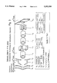
- FIG. 1 shows a diagrammatic plan view of a mass spectrometer with ICP ion source or flame, interface, magnetic sector, electric sector and ion detector,
- FIG. 2 shows a representation similar to FIG. 1 with a more detailed illustration of the interface or the ion optical system belonging thereto as well as the electrical insulation,
- FIG. 3 shows a diagrammatic representation of the ion optical system from a sampler to an end slit or to the entrance slit of the magnetic sector
- FIG. 6 shows a graphical representation according to FIG. 5, but for a new mode of operation
- FIG. 7 shows a graphical representation of the accelerating voltage and of the magnetic field according to FIG. 6, but considered over a longer period of time
- FIG. 8 shows a graphical representation of the accelerating voltage for a very short period of time
- FIG. 9 shows a block diagram to explain the new mode of operation.
- an ion source 10 operating according to the principle of the inductive coupled plasma (ICP), with an ICP flame 11 and an interface 12 disposed to follow the latter is provided.
- the ICP flame is generated and controlled by an appropriate coil 13.
- the ion trajectory is designated by the numeral 14.
- a device for separating the ions Disposed to follow the interface 12 there is a device for separating the ions, an analyser 15 with a magnetic sector 16 and an electric sector 17. The latter is surrounded by a housing 18, in which a device for detecting the ions, an ion detector 19 is also disposed.
- sampler 20 In the interface 12 there are disposed in succession in the direction of the ion trajectory a sampler 20, a skimmer 21, a lens arrangement 22, a diaphragm 23, a lens system 24, a further diaphragm 25 and an end slit 26.
- Sampler 20, skimmer 21, diaphragm 23 and diaphragm 25 define in each instance limits between individual pressure stages, to which corresponding vacuum pumps P1, P2, P3 and P4 are allocated or are connected to the same.
- the pressure stage with the pump P4 lies, in the direction of the ion trajectory, after the diaphragm 25, at least after the end slit 26.
- a flight tube 27 emerges from the interface 12. In this flight tube, the same pressure prevails as in the region connected to the pump P4 in the interface 12. Usually, the flight tube forms the spatial limitation of the ion beam.
- the flight tube 27 extends through the magnetic sector 16 and is in this region provided with a reduced cross-section and is electrically insulated in relation to the pole pieces, which are not visible in the figure.
- an insulating foil which is suitable for this purpose is provided, e.g. a Kapton foil having a thickness of 75 ⁇ m.
- the flight tube 27 is connected to the housing 18.
- a diaphragm 30 or a narrow entrance slit for the ion trajectory is provided. This extends in the electric sector 17 between two jaws 31, 32 defining an electric field.
- the ion trajectory passes through a further slit 33 and then impinges on an ion trap 34, especially a conversion dynode with an associated electron multiplier 35.
- the described arrangement of the electric sector 17 after the magnetic sector 16 can also be exchanged.
- the ion detector 19 is then disposed in its own (not shown) housing after the magnetic sector 16.
- the pressures set by the pumps P1, P2, P3, P4 as well as the voltages applied to the sampler 20, the skimmer 21 and the diaphragms 23, 25 as well as the shaping of the components acted upon by voltage are coordinated with one another. While the ICP flame 11 is maintained at atmospheric pressure, the pressure in the vacuum stage V1 allocated to the pump P1, that is to say between sampler 20 and skimmer 21, is approximately 1 mbar. Accordingly, the pressures in the stages V2, V3 and V4 are approximately 10 -3 mbar, 10 -5 mbar and 10 -7 bar. The last-mentioned pressure thus also prevails in the flight tube 27 and in the housing of the electric sector 17.
- FIG. 2 corresponds to that in FIG. 1.
- a plasma source especially according to the ICP principle with a corresponding ICP flame.
- the interface 12 exhibits a housing 37 to receive the ion optical system 36 and to form the individual vacuum stages or pressure stages V1, V2, V3 and V4. Appropriate means for electrical insulation and for sealing off are provided in the housing 37.
- the housing 37 is itself grounded, just like the sampler 20 and skimmer 21 enclosing between them a housing head 38 and the first pressure stage V1.
- an opening 39 for a connecting line of the pump P1 (FIG. 1) is shown at the bottom at the head 38.
- Corresponding openings 40, 41, 42 for connection of the pumps P2, P3, P4 and for the evacuation of the pressure stages V2, V3 and V4 are represented to the right of the opening 39.
- housing flanges 43, 44 In the interior of the housing 37 there are disposed, at a spacing from one another, two housing flanges 43, 44, between which the pressure stage V3 lies, in which the ion optical system 36 is also disposed. The latter is held by an optical system flange 45 connected to the flange 44. To this end, a screw connection (not shown) can be provided.
- the flanges 44, 45 are insulated in relation to one another by a thin foil 46. A similar, but not shown insulation is provided between the flange 43 and a head 47 of the ion optical system 36. As a result of this, the individual ion-optical components can be acted upon by high voltage, without the housing 37 itself being subjected to voltage.
- a tubular screening 48 which ends at a spacing ahead of an end flange 49 at the transition to the flight tube 27.
- End flange 49 and flight tube 27 are at high voltage and are appropriately electrically insulated in relation to a neighbouring housing flange 50 and moreover sealed off against the entry of air.
- the special sealing off is represented on an enlarged scale in the detailed drawing FIG. 2a of FIG. 2.
- a thin foil 53 for electrical insulation is clamped.
- Kapton foils can for example be used. Naturally, other thin insulating materials are also possible.
- the same type of insulation or vacuum sealing off is provided between the magnetic sector and the electric sector, more precisely at the entrance of the flight tube 27 into the housing 18 of the electric sector 17.
- FIG. 3 the individual components of the ion optical system 36 are represented in diagrammatic form and in an exploded view, as are the pressure conditions effective along the ion optical system and, in conjunction with the table associated with FIG. 3, the pertinent voltages as well.
- S1 sampler 20
- S2 skimmer 21
- Sampler and skimmer are at 0 V.
- pressure stage V2 Between the skimmer and a first lens L1--in the head 47--approximately 10 -3 mbar prevails (pressure stage V2).
- the remaining ion-optical components L2 to L7 are all part of the ion optical system 36, disposed in the region of the pressure stage V3 and acted upon by the voltages according to the table.
- the entrance slit 26 (S3) is disposed within the screening tube 48 or at its end and at the same time forms the boundary to the last pressure stage V4 (10 -7 mbar).
- the end slit 26 is acted upon by the full high voltage, in this case -8 kV.
- FIGS. 4a to 4e Various possibilities of the electrical insulation between the flight tube 27 and an electromagnet 54 of the magnetic sector 16 are represented in FIGS. 4a to 4e.
- the magnet 54 exhibits a coil 55 and pole pieces 56, 57. According to FIG. 4a, the magnet 54 with the pole pieces 56, 57 is grounded.
- the flight tube 27 is at high voltage and is at the same time vacuum chamber for the ion beam.
- foils 58 are disposed between flight tube 27 and the pole pieces 56, 57 for insulation.
- the magnet including the pole pieces is displaced relative to the flight tube 27 (vacuum chamber).
- FIG. 4c Another particular feature is shown in FIG. 4c.
- the pole pieces 56, 57 are in the vacuum, that is to say disposed within the flight tube 27.
- the latter is designed to be correspondingly higher in this region.
- the magnet 54 is again grounded, with insulations 58 in relation to the flight tube 27 and thus also in relation to the pole pieces 56, 57.
- the particular advantage of this embodiment resides in that the air gap between the pole pieces is enlarged by twice the wall thickness of the flight tube 27.
- FIG. 4d Another solution is shown in FIG. 4d.
- the magnet 54 with pole pieces 56, 57 and the flight tube 27 is set at high voltage.
- FIG. 4e shows an overall elevated magnet 54, including the coil 55.
- the insulation takes place here via an isolating transformer 59.
- a regulator 60 associated with the magnet 54 is likewise at high voltage.
- the mass spectrometer is as such double-focussing, and, as previously described, set at high voltage in the region of the ion optical system 36, of the magnetic sector 16 and of the electric sector 17. Only sampler 20 and skimmer 21 are grounded which inherently grounds the plasma or the flame 11. This is because the plasma is highly conductive once it is near atmospheric pressure as discussed above. This potential arrangement gives substantial advantages in a plurality of regions.
- the sampler 20 is usually provided with a water cooling which is not shown in greater detail. In the prior art, this part is under high voltage. The water circuit must be insulated in correspondingly costly fashion. It is necessary to use multi-deionized water. In the case of the arrangement according to the invention, such measures are not necessary.
- the high voltage is approximately -8 kV (for positive ions) and is present in its full extent at the latest at the lens L6 (FIG. 3).
- the lenses or respectively lens systems L1 to L5 disposed ahead in each instance are at somewhat lower potentials of -1 kV to -3 kV.
- the described mass spectrometer is prepared for a particular mode of operation. Specifically, the magnetic field of the magnetic sector 16 and at the same time the overall prevailing accelerating voltage are varied in a manner coordinated with one another. A synchronization of the two quantities is present.
- FIG. 5 the prior art is described with reference to FIG. 5.
- FIGS. 6 to 9 in turn concern the invention.
- FIG. 5 concerning the prior art (FIG. 5):
- FIG. 6 shows the novel type of scan which is provided in the case of the mass spectrometer according to the invention.
- the breakdown of the diagrams corresponds to that in FIG. 5.
- the magnetic field B m is slowly and steadily altered (scanned) in accordance with a prescribed time function.
- the accelerating voltage does not remain constant, but is synchronized with the magnetic field, and specifically with respect to the masses (mass/charge ratio) to be detected.
- the alteration of the accelerating voltage U acc takes place so that the effect of the alteration of the magnetic field is compensated and the mass spectrometer detects the mass M1, in total, for a time interval ⁇ T M1 .
- the accelerating voltage is altered for example by approximately 200 V (minimum to maximum), that is to say that a fluctuation of approximately ⁇ 100 V takes place about the highest potential -8 kV represented in the table relating to FIG. 3.
- the applied voltages are not altered by the same fixed amount, but are in each instance acted upon by the same factor, so that the relative alteration of the voltage is the same.
- the voltage alteration is undertaken on all components which are under voltage and influence the ion trajectory.
- FIG. 7 shows once again the magnetic field (bottom) and the accelerating voltage (top) in time-lapse sequence.
- a scan of the magnetic field that is to say during a rise from minimum to maximum, a plurality of sawtooth-type scans (of each respective mass to be detected) of the accelerating voltage are carried out.
- the converging envelope curves which are obtained are shown in broken lines.
- the jump back by the value ⁇ B m takes place in a somewhat longer time, relative to the remaining time, than as shown in FIG. 7.
- the magnetic field can also be scanned downwards.
- the described repetition of the individual scans is designated as repeating mode of operation.
- FIG. 8 shows once again the alteration of the accelerating voltage with reference to specific numerical values.
- the accelerating voltage is lowered by 200 V within 170 ⁇ sec.
- the "standard value" of the potential is, in this example, at 10 kV.
- the accelerating voltage follows at approximately 120 V/msec. During a time interval of 1.33 msec, in this case the ion mass 50 Da is registered at the detector.
- the mentioned short time interval is also shown in FIG. 8.
- FIG. 9 shows the cooperation of various electronic assemblies to realize the described synchronous mode of operation.
- a scan function stored in the (front end) ⁇ processor is parametrized and activated.
- the two scan generators 1 and 2 which govern the temporal progression of the accelerating voltage and of the magnetic field, are driven.
- Signal processor and also both scan generators are synchronously clocked via the time base.
- the digital control pulses are passed via optocouplers to D/A converters; subsequently, in the high voltage unit the required accelerating voltage is generated, and, respectively, in the field regulator the corresponding magnetic flux is generated.
- the principle of the digital control of the voltage and respectively of the magnetic field is known in mass spectrometry and therefore does not need to be explained in greater detail here.
- the described mass spectrometer with the analyser which is at high voltage is particularly advantageous for the proposed synchronized mode of operation.
- the voltage of the components which are correspondingly acted upon is alterable with relatively small time constants.
- the plasma source itself is not affected by this, since said source is grounded. The situation would be different in the case of a plasma source which is at high potential. Such a source, including the plasma, would then have to be scanned in terms of potential.
- the invention is particularly suitable for element analysis, especially multielement analysis, in which the relative mass range to be covered is relatively large. What matters principally is the question of whether and how many masses, known in terms of magnitude, are present in a specimen.
- the described analyser which is at high electrical potential, especially with the interface and the ion optical system, can also be used with other ion sources.
Abstract
Description
Claims (12)
Applications Claiming Priority (2)
| Application Number | Priority Date | Filing Date | Title |
|---|---|---|---|
| DE4333469A DE4333469A1 (en) | 1993-10-01 | 1993-10-01 | Mass spectrometer with ICP source |
| DE4333469.5 | 1993-10-01 |
Publications (1)
| Publication Number | Publication Date |
|---|---|
| US5552599A true US5552599A (en) | 1996-09-03 |
Family
ID=6499152
Family Applications (1)
| Application Number | Title | Priority Date | Filing Date |
|---|---|---|---|
| US08/315,569 Expired - Lifetime US5552599A (en) | 1993-10-01 | 1994-09-30 | Mass spectrometer having an ICP source |
Country Status (3)
| Country | Link |
|---|---|
| US (1) | US5552599A (en) |
| DE (1) | DE4333469A1 (en) |
| GB (1) | GB2282479B (en) |
Cited By (23)
| Publication number | Priority date | Publication date | Assignee | Title |
|---|---|---|---|---|
| WO2001085312A1 (en) * | 2000-05-08 | 2001-11-15 | Mass Sensors, Inc. | Microscale mass spectrometric chemical-gas sensor |
| US6573517B1 (en) * | 1999-07-30 | 2003-06-03 | Sumitomo Eaton Nova Corporation | Ion implantation apparatus |
| US6720563B1 (en) * | 1999-07-30 | 2004-04-13 | Sumitomo Eaton Nova Corporation | Ion implantation apparatus and ion implantation method |
| US6831276B2 (en) | 2000-05-08 | 2004-12-14 | Philip S. Berger | Microscale mass spectrometric chemical-gas sensor |
| US20060017388A1 (en) * | 2004-07-22 | 2006-01-26 | Stevenson Hugh C | Radio frequency power generator |
| US20060275166A1 (en) * | 2005-05-20 | 2006-12-07 | Magneti Marelli Powertrain S.P.A. | Fuel pump for an internal combustion engine |
| US20070205362A1 (en) * | 2006-03-03 | 2007-09-06 | Ionsense, Inc. | Sampling system for use with surface ionization spectroscopy |
| US20080067348A1 (en) * | 2006-05-26 | 2008-03-20 | Ionsense, Inc. | High resolution sampling system for use with surface ionization technology |
| US20080087812A1 (en) * | 2006-10-13 | 2008-04-17 | Ionsense, Inc. | Sampling system for containment and transfer of ions into a spectroscopy system |
| US7372019B2 (en) | 2005-05-18 | 2008-05-13 | Spectro Analytical Instruments Gmbh & Co. Kg | ICP mass spectrometer |
| US20090090858A1 (en) * | 2006-03-03 | 2009-04-09 | Ionsense, Inc. | Sampling system for use with surface ionization spectroscopy |
| US8207497B2 (en) | 2009-05-08 | 2012-06-26 | Ionsense, Inc. | Sampling of confined spaces |
| US8440965B2 (en) | 2006-10-13 | 2013-05-14 | Ionsense, Inc. | Sampling system for use with surface ionization spectroscopy |
| US8754365B2 (en) | 2011-02-05 | 2014-06-17 | Ionsense, Inc. | Apparatus and method for thermal assisted desorption ionization systems |
| US8901488B1 (en) | 2011-04-18 | 2014-12-02 | Ionsense, Inc. | Robust, rapid, secure sample manipulation before during and after ionization for a spectroscopy system |
| US9337007B2 (en) | 2014-06-15 | 2016-05-10 | Ionsense, Inc. | Apparatus and method for generating chemical signatures using differential desorption |
| WO2017137390A1 (en) * | 2016-02-08 | 2017-08-17 | Luxembourg Institute Of Science And Technology (List) | Floating magnet for a mass spectrometer |
| US9899196B1 (en) | 2016-01-12 | 2018-02-20 | Jeol Usa, Inc. | Dopant-assisted direct analysis in real time mass spectrometry |
| CN107924808A (en) * | 2015-08-14 | 2018-04-17 | 塞莫费雪科学(不来梅)有限公司 | Multi-detector mass spectrograph and spectrum assay method |
| US10636640B2 (en) | 2017-07-06 | 2020-04-28 | Ionsense, Inc. | Apparatus and method for chemical phase sampling analysis |
| US10825673B2 (en) | 2018-06-01 | 2020-11-03 | Ionsense Inc. | Apparatus and method for reducing matrix effects |
| US11424116B2 (en) | 2019-10-28 | 2022-08-23 | Ionsense, Inc. | Pulsatile flow atmospheric real time ionization |
| US11913861B2 (en) | 2020-05-26 | 2024-02-27 | Bruker Scientific Llc | Electrostatic loading of powder samples for ionization |
Citations (7)
| Publication number | Priority date | Publication date | Assignee | Title |
|---|---|---|---|---|
| SU995156A1 (en) * | 1981-09-16 | 1983-02-07 | Институт Ядерной Физики Ан Казсср | Prizm-mass spectrometer |
| SU723980A1 (en) * | 1978-07-21 | 1984-06-07 | Институт Ядерной Физики Ан Казсср | Prismatic magnetic mass-spectrometer |
| US4472631A (en) * | 1982-06-04 | 1984-09-18 | Research Corporation | Combination of time resolution and mass dispersive techniques in mass spectrometry |
| US4804838A (en) * | 1986-07-07 | 1989-02-14 | Shimadzu Corporation | Inductively-coupled radio frequency plasma mass spectrometer |
| WO1989012313A1 (en) * | 1988-06-03 | 1989-12-14 | Vg Instruments Group Limited | High resolution plasma mass spectrometer |
| WO1992016008A1 (en) * | 1991-03-11 | 1992-09-17 | Fisons Plc | Isotopic-ratio plasma source mass spectrometer |
| US5218204A (en) * | 1992-05-27 | 1993-06-08 | Iowa State University Research Foundation, Inc. | Plasma sampling interface for inductively coupled plasma-mass spectrometry (ICP-MS) |
Family Cites Families (3)
| Publication number | Priority date | Publication date | Assignee | Title |
|---|---|---|---|---|
| US4435642A (en) * | 1982-03-24 | 1984-03-06 | The United States Of America As Represented By The United States National Aeronautics And Space Administration | Ion mass spectrometer |
| GB8917570D0 (en) * | 1989-08-01 | 1989-09-13 | Vg Instr Group | Plasma source mass spectrometry |
| JP2593587B2 (en) * | 1991-03-12 | 1997-03-26 | 株式会社日立製作所 | Plasma ion source trace element mass spectrometer |
-
1993
- 1993-10-01 DE DE4333469A patent/DE4333469A1/en not_active Withdrawn
-
1994
- 1994-09-23 GB GB9419238A patent/GB2282479B/en not_active Expired - Lifetime
- 1994-09-30 US US08/315,569 patent/US5552599A/en not_active Expired - Lifetime
Patent Citations (8)
| Publication number | Priority date | Publication date | Assignee | Title |
|---|---|---|---|---|
| SU723980A1 (en) * | 1978-07-21 | 1984-06-07 | Институт Ядерной Физики Ан Казсср | Prismatic magnetic mass-spectrometer |
| SU995156A1 (en) * | 1981-09-16 | 1983-02-07 | Институт Ядерной Физики Ан Казсср | Prizm-mass spectrometer |
| US4472631A (en) * | 1982-06-04 | 1984-09-18 | Research Corporation | Combination of time resolution and mass dispersive techniques in mass spectrometry |
| US4804838A (en) * | 1986-07-07 | 1989-02-14 | Shimadzu Corporation | Inductively-coupled radio frequency plasma mass spectrometer |
| WO1989012313A1 (en) * | 1988-06-03 | 1989-12-14 | Vg Instruments Group Limited | High resolution plasma mass spectrometer |
| WO1992016008A1 (en) * | 1991-03-11 | 1992-09-17 | Fisons Plc | Isotopic-ratio plasma source mass spectrometer |
| US5352893A (en) * | 1991-03-11 | 1994-10-04 | Fisons Plc | Isotopic-ratio plasma source mass spectrometer |
| US5218204A (en) * | 1992-05-27 | 1993-06-08 | Iowa State University Research Foundation, Inc. | Plasma sampling interface for inductively coupled plasma-mass spectrometry (ICP-MS) |
Non-Patent Citations (2)
| Title |
|---|
| Article entitled "The Ion Mass Spectrometer on Giotto", by H. Balsiger et al, J. Phys. E:Sci. Instrum. 20, 1987 S.759-767. |
| Article entitled The Ion Mass Spectrometer on Giotto , by H. Balsiger et al, J. Phys. E:Sci. Instrum. 20, 1987 S.759 767. * |
Cited By (69)
| Publication number | Priority date | Publication date | Assignee | Title |
|---|---|---|---|---|
| US6573517B1 (en) * | 1999-07-30 | 2003-06-03 | Sumitomo Eaton Nova Corporation | Ion implantation apparatus |
| US6720563B1 (en) * | 1999-07-30 | 2004-04-13 | Sumitomo Eaton Nova Corporation | Ion implantation apparatus and ion implantation method |
| WO2001085312A1 (en) * | 2000-05-08 | 2001-11-15 | Mass Sensors, Inc. | Microscale mass spectrometric chemical-gas sensor |
| US6590207B2 (en) | 2000-05-08 | 2003-07-08 | Mass Sensors, Inc. | Microscale mass spectrometric chemical-gas sensor |
| US6831276B2 (en) | 2000-05-08 | 2004-12-14 | Philip S. Berger | Microscale mass spectrometric chemical-gas sensor |
| US20060017388A1 (en) * | 2004-07-22 | 2006-01-26 | Stevenson Hugh C | Radio frequency power generator |
| US7214934B2 (en) * | 2004-07-22 | 2007-05-08 | Varian Australia Pty Ltd | Radio frequency power generator |
| US7372019B2 (en) | 2005-05-18 | 2008-05-13 | Spectro Analytical Instruments Gmbh & Co. Kg | ICP mass spectrometer |
| US20060275166A1 (en) * | 2005-05-20 | 2006-12-07 | Magneti Marelli Powertrain S.P.A. | Fuel pump for an internal combustion engine |
| US20070205362A1 (en) * | 2006-03-03 | 2007-09-06 | Ionsense, Inc. | Sampling system for use with surface ionization spectroscopy |
| US8525109B2 (en) | 2006-03-03 | 2013-09-03 | Ionsense, Inc. | Sampling system for use with surface ionization spectroscopy |
| US8497474B2 (en) | 2006-03-03 | 2013-07-30 | Ionsense Inc. | Sampling system for use with surface ionization spectroscopy |
| US8217341B2 (en) | 2006-03-03 | 2012-07-10 | Ionsense | Sampling system for use with surface ionization spectroscopy |
| US8026477B2 (en) | 2006-03-03 | 2011-09-27 | Ionsense, Inc. | Sampling system for use with surface ionization spectroscopy |
| US20100102222A1 (en) * | 2006-03-03 | 2010-04-29 | Ionsense, Inc. | Sampling system for use with surface ionization spectroscopy |
| US20090090858A1 (en) * | 2006-03-03 | 2009-04-09 | Ionsense, Inc. | Sampling system for use with surface ionization spectroscopy |
| US7700913B2 (en) | 2006-03-03 | 2010-04-20 | Ionsense, Inc. | Sampling system for use with surface ionization spectroscopy |
| US20080067348A1 (en) * | 2006-05-26 | 2008-03-20 | Ionsense, Inc. | High resolution sampling system for use with surface ionization technology |
| US8481922B2 (en) | 2006-05-26 | 2013-07-09 | Ionsense, Inc. | Membrane for holding samples for use with surface ionization technology |
| US7714281B2 (en) | 2006-05-26 | 2010-05-11 | Ionsense, Inc. | Apparatus for holding solids for use with surface ionization technology |
| US20100140468A1 (en) * | 2006-05-26 | 2010-06-10 | Ionsense, Inc. | Apparatus for holding solids for use with surface ionization technology |
| US7777181B2 (en) | 2006-05-26 | 2010-08-17 | Ionsense, Inc. | High resolution sampling system for use with surface ionization technology |
| US20080067359A1 (en) * | 2006-05-26 | 2008-03-20 | Ionsense, Inc. | Flexible open tube sampling system for use with surface ionization technology |
| US7705297B2 (en) * | 2006-05-26 | 2010-04-27 | Ionsense, Inc. | Flexible open tube sampling system for use with surface ionization technology |
| US20080067358A1 (en) * | 2006-05-26 | 2008-03-20 | Ionsense, Inc. | Apparatus for holding solids for use with surface ionization technology |
| WO2007140351A3 (en) * | 2006-05-26 | 2008-04-17 | Ionsense Inc | Flexible open tube sampling system for use with surface ionization technology |
| US8421005B2 (en) | 2006-05-26 | 2013-04-16 | Ionsense, Inc. | Systems and methods for transfer of ions for analysis |
| US20080087812A1 (en) * | 2006-10-13 | 2008-04-17 | Ionsense, Inc. | Sampling system for containment and transfer of ions into a spectroscopy system |
| US8440965B2 (en) | 2006-10-13 | 2013-05-14 | Ionsense, Inc. | Sampling system for use with surface ionization spectroscopy |
| US7928364B2 (en) | 2006-10-13 | 2011-04-19 | Ionsense, Inc. | Sampling system for containment and transfer of ions into a spectroscopy system |
| US8207497B2 (en) | 2009-05-08 | 2012-06-26 | Ionsense, Inc. | Sampling of confined spaces |
| US8563945B2 (en) | 2009-05-08 | 2013-10-22 | Ionsense, Inc. | Sampling of confined spaces |
| US8729496B2 (en) | 2009-05-08 | 2014-05-20 | Ionsense, Inc. | Sampling of confined spaces |
| US9390899B2 (en) | 2009-05-08 | 2016-07-12 | Ionsense, Inc. | Apparatus and method for sampling of confined spaces |
| US10643834B2 (en) | 2009-05-08 | 2020-05-05 | Ionsense, Inc. | Apparatus and method for sampling |
| US8895916B2 (en) | 2009-05-08 | 2014-11-25 | Ionsense, Inc. | Apparatus and method for sampling of confined spaces |
| US10090142B2 (en) | 2009-05-08 | 2018-10-02 | Ionsense, Inc | Apparatus and method for sampling of confined spaces |
| US9633827B2 (en) | 2009-05-08 | 2017-04-25 | Ionsense, Inc. | Apparatus and method for sampling of confined spaces |
| US8754365B2 (en) | 2011-02-05 | 2014-06-17 | Ionsense, Inc. | Apparatus and method for thermal assisted desorption ionization systems |
| US11049707B2 (en) | 2011-02-05 | 2021-06-29 | Ionsense, Inc. | Apparatus and method for thermal assisted desorption ionization systems |
| US10643833B2 (en) | 2011-02-05 | 2020-05-05 | Ionsense, Inc. | Apparatus and method for thermal assisted desorption ionization systems |
| US8822949B2 (en) | 2011-02-05 | 2014-09-02 | Ionsense Inc. | Apparatus and method for thermal assisted desorption ionization systems |
| US9514923B2 (en) | 2011-02-05 | 2016-12-06 | Ionsense Inc. | Apparatus and method for thermal assisted desorption ionization systems |
| US9960029B2 (en) | 2011-02-05 | 2018-05-01 | Ionsense, Inc. | Apparatus and method for thermal assisted desorption ionization systems |
| US8963101B2 (en) | 2011-02-05 | 2015-02-24 | Ionsense, Inc. | Apparatus and method for thermal assisted desorption ionization systems |
| US11742194B2 (en) | 2011-02-05 | 2023-08-29 | Bruker Scientific Llc | Apparatus and method for thermal assisted desorption ionization systems |
| US9224587B2 (en) | 2011-02-05 | 2015-12-29 | Ionsense, Inc. | Apparatus and method for thermal assisted desorption ionization systems |
| US8901488B1 (en) | 2011-04-18 | 2014-12-02 | Ionsense, Inc. | Robust, rapid, secure sample manipulation before during and after ionization for a spectroscopy system |
| US9105435B1 (en) | 2011-04-18 | 2015-08-11 | Ionsense Inc. | Robust, rapid, secure sample manipulation before during and after ionization for a spectroscopy system |
| US11295943B2 (en) | 2014-06-15 | 2022-04-05 | Ionsense Inc. | Apparatus and method for generating chemical signatures using differential desorption |
| US9558926B2 (en) | 2014-06-15 | 2017-01-31 | Ionsense, Inc. | Apparatus and method for rapid chemical analysis using differential desorption |
| US10056243B2 (en) | 2014-06-15 | 2018-08-21 | Ionsense, Inc. | Apparatus and method for rapid chemical analysis using differential desorption |
| US9824875B2 (en) | 2014-06-15 | 2017-11-21 | Ionsense, Inc. | Apparatus and method for generating chemical signatures using differential desorption |
| US10283340B2 (en) | 2014-06-15 | 2019-05-07 | Ionsense, Inc. | Apparatus and method for generating chemical signatures using differential desorption |
| US10553417B2 (en) | 2014-06-15 | 2020-02-04 | Ionsense, Inc. | Apparatus and method for generating chemical signatures using differential desorption |
| US10825675B2 (en) | 2014-06-15 | 2020-11-03 | Ionsense Inc. | Apparatus and method for generating chemical signatures using differential desorption |
| US9337007B2 (en) | 2014-06-15 | 2016-05-10 | Ionsense, Inc. | Apparatus and method for generating chemical signatures using differential desorption |
| CN107924808A (en) * | 2015-08-14 | 2018-04-17 | 塞莫费雪科学(不来梅)有限公司 | Multi-detector mass spectrograph and spectrum assay method |
| CN107924808B (en) * | 2015-08-14 | 2020-02-07 | 塞莫费雪科学(不来梅)有限公司 | Multi-detector mass spectrometer and spectrometry method |
| US9899196B1 (en) | 2016-01-12 | 2018-02-20 | Jeol Usa, Inc. | Dopant-assisted direct analysis in real time mass spectrometry |
| LU92970B1 (en) * | 2016-02-08 | 2017-09-19 | Luxembourg Inst Science & Tech List | Floating magnet for a mass spectrometer |
| US10580635B2 (en) * | 2016-02-08 | 2020-03-03 | Luxembourg Institute Of Science And Technology (List) | Floating magnet for a mass spectrometer |
| JP2019509584A (en) * | 2016-02-08 | 2019-04-04 | ルクセンブルク インスティトゥート オブ サイエンス アンド テクノロジー(リスト) | Floating magnet for mass spectrometer |
| US20190057853A1 (en) * | 2016-02-08 | 2019-02-21 | Luxembourg Institute Of Science And Technology (List) | Floating Magnet For A Mass Spectrometer |
| WO2017137390A1 (en) * | 2016-02-08 | 2017-08-17 | Luxembourg Institute Of Science And Technology (List) | Floating magnet for a mass spectrometer |
| US10636640B2 (en) | 2017-07-06 | 2020-04-28 | Ionsense, Inc. | Apparatus and method for chemical phase sampling analysis |
| US10825673B2 (en) | 2018-06-01 | 2020-11-03 | Ionsense Inc. | Apparatus and method for reducing matrix effects |
| US11424116B2 (en) | 2019-10-28 | 2022-08-23 | Ionsense, Inc. | Pulsatile flow atmospheric real time ionization |
| US11913861B2 (en) | 2020-05-26 | 2024-02-27 | Bruker Scientific Llc | Electrostatic loading of powder samples for ionization |
Also Published As
| Publication number | Publication date |
|---|---|
| GB2282479A (en) | 1995-04-05 |
| GB2282479B (en) | 1997-08-13 |
| DE4333469A1 (en) | 1995-04-06 |
| GB9419238D0 (en) | 1994-11-09 |
Similar Documents
| Publication | Publication Date | Title |
|---|---|---|
| US5552599A (en) | Mass spectrometer having an ICP source | |
| EP1875486B1 (en) | Method for controlling space charge-driven ion instabilities in electron impact ion sources | |
| US7196525B2 (en) | Sample imaging | |
| US4650999A (en) | Method of mass analyzing a sample over a wide mass range by use of a quadrupole ion trap | |
| Von Zahn | Monopole spectrometer, a new electric field mass spectrometer | |
| US3769600A (en) | Method of and apparatus for producing energetic charged particle extended dimension beam curtains and pulse producing structures therefor | |
| EP0113207A2 (en) | Method of mass analyzing a sample by use of a quadrupole ion trap | |
| US20080272289A1 (en) | Linear tof geometry for high sensitivity at high mass | |
| JP2724416B2 (en) | High-resolution plasma mass spectrometer | |
| CN108028168B (en) | Secondary ion mass spectrometer and secondary ion mass spectrometry | |
| IL45710A (en) | Mass spectrometer | |
| US4924089A (en) | Method and apparatus for the accumulation of ions in a trap of an ion cyclotron resonance spectrometer, by transferring the kinetic energy of the motion parallel to the magnetic field into directions perpendicular to the magnetic field | |
| US5898173A (en) | High resolution ion detection for linear time-of-flight mass spectrometers | |
| US7112787B2 (en) | Ion trap mass spectrometer and method for analyzing ions | |
| US3787681A (en) | A method for analysis by producing a mass spectrum by mass separation in a magnetic sector field of a mass spectrometer utilizing ionization of a sample substance by electron bombardment | |
| US5043575A (en) | Process for the mass-spectrometric investigation of isotopes, as well as isotope mass spectrometer | |
| US4117322A (en) | Ion scattering spectrometer including cylindrical mirror analyzer and ion gun axially positioned therewithin | |
| JPS6016063B2 (en) | Plasma sampling device and method | |
| US4695724A (en) | AC-modulation quadrupole mass spectrometer | |
| US10948456B1 (en) | Gas analyzer system with ion source | |
| Braams et al. | Composition of Noble Gas Ion Beams Produced with a Duoplasmatron | |
| JP2000077025A (en) | Quadrupole mass spectrometer | |
| EP4235746A1 (en) | Method and apparatus of mass analysing positively charged ions and negatively charged ions | |
| US20220344144A1 (en) | Method and apparatus | |
| JP2926782B2 (en) | High frequency inductively coupled plasma mass spectrometer |
Legal Events
| Date | Code | Title | Description |
|---|---|---|---|
| AS | Assignment |
Owner name: FINNIGAN MAT GMBH, GERMANY Free format text: ASSIGNMENT OF ASSIGNORS INTEREST;ASSIGNORS:GEISSMANN, ULRICH;JUNG, GERHARD;BRUNNEE, CURT;REEL/FRAME:007199/0021 Effective date: 19940915 |
|
| STCF | Information on status: patent grant |
Free format text: PATENTED CASE |
|
| FPAY | Fee payment |
Year of fee payment: 4 |
|
| AS | Assignment |
Owner name: THERMO FINNIGAN MAT GMBH, GERMANY Free format text: CHANGE OF NAME;ASSIGNOR:FINNIGAN MAT GMBH;REEL/FRAME:013774/0946 Effective date: 20010827 |
|
| FPAY | Fee payment |
Year of fee payment: 8 |
|
| AS | Assignment |
Owner name: THERMO ELECTRON (BREMEN) GMBH, GERMANY Free format text: CHANGE OF NAME;ASSIGNOR:THERMO FINNIGAN MAT GMBH;REEL/FRAME:016016/0679 Effective date: 20040924 |
|
| FEPP | Fee payment procedure |
Free format text: PAYOR NUMBER ASSIGNED (ORIGINAL EVENT CODE: ASPN); ENTITY STATUS OF PATENT OWNER: LARGE ENTITY |
|
| FPAY | Fee payment |
Year of fee payment: 12 |
|
| AS | Assignment |
Owner name: THERMO FISHER SCIENTIFIC (BREMEN) GMBH, GERMANY Free format text: CHANGE OF NAME;ASSIGNOR:THERMO ELECTRON (BREMEN) GMBH;REEL/FRAME:024733/0161 Effective date: 20061121 |