US554751A - Neck-yoke - Google Patents
Neck-yoke Download PDFInfo
- Publication number
- US554751A US554751A US554751DA US554751A US 554751 A US554751 A US 554751A US 554751D A US554751D A US 554751DA US 554751 A US554751 A US 554751A
- Authority
- US
- United States
- Prior art keywords
- yoke
- neck
- frame
- pole
- socket
- Prior art date
- Legal status (The legal status is an assumption and is not a legal conclusion. Google has not performed a legal analysis and makes no representation as to the accuracy of the status listed.)
- Expired - Lifetime
Links
Images
Classifications
-
- B—PERFORMING OPERATIONS; TRANSPORTING
- B62—LAND VEHICLES FOR TRAVELLING OTHERWISE THAN ON RAILS
- B62C—VEHICLES DRAWN BY ANIMALS
- B62C5/00—Draught assemblies
- B62C5/04—Swingletrees; Mountings thereof; Draught equalisers for a span of draught animals; Mountings for traces
Definitions
- My object is to provide a strong-jointed device for connecting pole-straps with the ends of a pole-yoke and specially adapted for preventing the annoyances and accidents incident to the ends of pole-yokes catching fast to fixed posts and other objects when horses are hitched to a wagon and tied to a post or other fixed object.
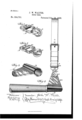
- My invention consists in the construction of the device and the combination thereof with a neck-yoke, as hereinafter set forth, pointed out in my claim and illustrated in the accompanying drawings, in which- Figure 1 is a perspective View showing the device for connecting the pole-strap with the socket.
- Fig. 2 is a like view showing a modified form in which the swivel-joint is omitted.
- Fig. 3 is a perspective view of the socket.
- Fig. 4 is a top view of the complete device applied to a neck-yoke.
- the reference-letter A is used to indicate the neclcyoke, which is of the ordinary form and B indicates a metal socket adapted to be placed on one of said ends to fit securely thereto.
- the socket B is an integral tapering projection at the surface of the socket B and extending the entire length of the socket at its broad end, and specially adapted for pivotally connecting a rigid frame to its small end in such a manner that the rigid extension 13 and the rigid frame pivoted thereto will serve as a guard for preventing the end of the pole-yoke from getting engaged with a post or other fixed object when the pole-yoke is connected with horses by means of straps.
- a jointed metal strap-holding device is thus produced that allows longitudinal motion to the poleyoke and prevents the ends of the poleyoke from engaging a post or other fixed obj ect, while at the same time apole-strap connecting the device with a collar on a horse allows a back-and-forth motion of the poleyoke relative to the horse and the pole with which the pole-yoke is connected.
- D indicates a substantially oblong frame, having a roller D extended transversely thereof and near one end thereof, whereby the end of the frame and the roller both lie within the loop of the pole-strap and keep the frame in line therewith.
- F is a bolt adapted to connect the frame D with the frame 0 in such a manner as to produce a swivel-joint between the two.
- each socket being provided with a rearwardly-projecting plate or extension, the outer edge of which is flush with the end of the yoke at the front and tapers inwardly to the rear, a metal frame overlapping the rear end of the plate and pivotally secured thereto to move in a plane parallel with the neck-yoke, and provided with a central hole, an oblong frame swiveled to the rear portion of the metal frame by means of a bolt'through the hole in the metal frame, and a roller journaled in the oblong frame, near one end thereof, and parallel with the neck-yoke, substantially as set forth.
Landscapes
- Engineering & Computer Science (AREA)
- Transportation (AREA)
- Mechanical Engineering (AREA)
- Buckles (AREA)
Description
(No Mbdel.)
J. W, WALTER} NECK YOKE.
No. 554,751. Patented Fe 96.
has straight slightly-tapered ends.
UNITED STATES PATENT .OFFICE.
JOHN XV. WALTER, OF VALERIA, IOWA.
NECK-YOKE.
SPECIFICATION forming part of Letters Patent No. 554,751, dated February 18, 1896. Application filed February 14, 1895. Serial No. 538,466. (No model.)
To all whom it may concern.-
Be it known that I, JOHN XV. VVALTER, a citizen of the United States of America, residing at Valeria, in the county of Jasper and State of Iowa, have invented a new and useful N eck-Yoke, of which the following is a specification.
My object is to provide a strong-jointed device for connecting pole-straps with the ends of a pole-yoke and specially adapted for preventing the annoyances and accidents incident to the ends of pole-yokes catching fast to fixed posts and other objects when horses are hitched to a wagon and tied to a post or other fixed object.
My invention consists in the construction of the device and the combination thereof with a neck-yoke, as hereinafter set forth, pointed out in my claim and illustrated in the accompanying drawings, in which- Figure 1 is a perspective View showing the device for connecting the pole-strap with the socket. Fig. 2 is a like view showing a modified form in which the swivel-joint is omitted. Fig. 3 is a perspective view of the socket. Fig. 4 is a top view of the complete device applied to a neck-yoke.
Referring to the accompanying drawings, the reference-letter A is used to indicate the neclcyoke, which is of the ordinary form and B indicates a metal socket adapted to be placed on one of said ends to fit securely thereto.
B is an integral tapering projection at the surface of the socket B and extending the entire length of the socket at its broad end, and specially adapted for pivotally connecting a rigid frame to its small end in such a manner that the rigid extension 13 and the rigid frame pivoted thereto will serve as a guard for preventing the end of the pole-yoke from getting engaged with a post or other fixed object when the pole-yoke is connected with horses by means of straps.
0 indicates a metal frame adapted to overlap the sides of the rear extremity'of the tapering extension 13 and provided with a central bore adapted to admit a rivet or bolt 0 whereby the said frame maybe pivotally connected with the tapering extension. A jointed metal strap-holding device is thus produced that allows longitudinal motion to the poleyoke and prevents the ends of the poleyoke from engaging a post or other fixed obj ect, while at the same time apole-strap connecting the device with a collar on a horse allows a back-and-forth motion of the poleyoke relative to the horse and the pole with which the pole-yoke is connected.
D indicates a substantially oblong frame, having a roller D extended transversely thereof and near one end thereof, whereby the end of the frame and the roller both lie within the loop of the pole-strap and keep the frame in line therewith.
F is a bolt adapted to connect the frame D with the frame 0 in such a manner as to produce a swivel-joint between the two.
II represents the pole-strap passed around the roller D and adapted to be attached to a horses collar.
In Fig. 2 the swivel-joint between the frame 0 and D is dispensed with and the device made complete in one piece to produce a cheaper device.
Having thus described my invention, what I claim as new therein, and desire to secure by Letters Patent of the United States therefor,.is-
The combination with a neck-yoke, of a socket secured to each end thereof, each socket being provided with a rearwardly-projecting plate or extension, the outer edge of which is flush with the end of the yoke at the front and tapers inwardly to the rear, a metal frame overlapping the rear end of the plate and pivotally secured thereto to move in a plane parallel with the neck-yoke, and provided with a central hole, an oblong frame swiveled to the rear portion of the metal frame by means of a bolt'through the hole in the metal frame, and a roller journaled in the oblong frame, near one end thereof, and parallel with the neck-yoke, substantially as set forth.
Witnesses:
Tnos. PHILSON, J. M.
JOHN W. WALTER.
Publications (1)
| Publication Number | Publication Date |
|---|---|
| US554751A true US554751A (en) | 1896-02-18 |
Family
ID=2623489
Family Applications (1)
| Application Number | Title | Priority Date | Filing Date |
|---|---|---|---|
| US554751D Expired - Lifetime US554751A (en) | Neck-yoke |
Country Status (1)
| Country | Link |
|---|---|
| US (1) | US554751A (en) |
-
0
- US US554751D patent/US554751A/en not_active Expired - Lifetime
Similar Documents
| Publication | Publication Date | Title |
|---|---|---|
| US352039A (en) | Teeeitoey | |
| US1034299A (en) | Draft apparatus. | |
| US558954A (en) | Whiffletree attachment | |
| US318169A (en) | Hitching device | |
| US424225A (en) | Harness | |
| US294521A (en) | Rein-guard | |
| US375080A (en) | Neck-yoke | |
| US413051A (en) | Shaft attachment for carriages | |
| US1022529A (en) | Tug and shaft attachment. | |
| US548319A (en) | Spreader-bar for harness-traces | |
| US216727A (en) | Improvement in whiffletree-hooks | |
| US199381A (en) | Improvement in apparatus for hitching and securing runaway horses | |
| US508023A (en) | Draft-evener | |
| US390883A (en) | Pole-tip | |
| US186147A (en) | Improvement in safety-hooks and breast-straps for harness | |
| US229176A (en) | Harness | |
| US179572A (en) | Improvement in whiffletree-hooks | |
| US346054A (en) | Draft-equalizer | |
| US183726A (en) | Improvement in draft-equalizers | |
| US979067A (en) | Harness attachment. | |
| US207304A (en) | Improvement in wagon poles and shafts | |
| US563591A (en) | Clamp | |
| US1179615A (en) | Breast-yoke. | |
| US438205A (en) | Coupling-bar for wire-fence rails | |
| US1488546A (en) | Harness attachment |