US554697A - William p - Google Patents
William p Download PDFInfo
- Publication number
- US554697A US554697A US554697DA US554697A US 554697 A US554697 A US 554697A US 554697D A US554697D A US 554697DA US 554697 A US554697 A US 554697A
- Authority
- US
- United States
- Prior art keywords
- car
- screw
- gear
- dynamo
- shaft
- Prior art date
- Legal status (The legal status is an assumption and is not a legal conclusion. Google has not performed a legal analysis and makes no representation as to the accuracy of the status listed.)
- Expired - Lifetime
Links
- 241000252141 Semionotiformes Species 0.000 description 2
- 238000010276 construction Methods 0.000 description 2
- 230000000875 corresponding Effects 0.000 description 2
- 230000005611 electricity Effects 0.000 description 2
- JVTAAEKCZFNVCJ-UHFFFAOYSA-N lactic acid Chemical compound CC(O)C(O)=O JVTAAEKCZFNVCJ-UHFFFAOYSA-N 0.000 description 2
Images
Classifications
-
- B—PERFORMING OPERATIONS; TRANSPORTING
- B65—CONVEYING; PACKING; STORING; HANDLING THIN OR FILAMENTARY MATERIAL
- B65G—TRANSPORT OR STORAGE DEVICES, e.g. CONVEYORS FOR LOADING OR TIPPING, SHOP CONVEYOR SYSTEMS OR PNEUMATIC TUBE CONVEYORS
- B65G33/00—Screw or rotary spiral conveyors
- B65G33/02—Screw or rotary spiral conveyors for articles
- B65G33/04—Screw or rotary spiral conveyors for articles conveyed between a single screw and guiding means
Definitions
- My invention relates to improvements in llighting cars, and particularly such cars as are propelled by a moving source of power, such as a screw along the track.
- the objects of my invention are to produce a simple and convenient means of running an electric generator, such as a dynamo, from the source of power which propels the car and to arrange the apparatus so that the dynamo can be constantly run whether the car is in motion or not; also to arrange and support the dynamo and its driving mechanism in such a manner that the driving mechanism will not be aected by the rise and fall of the car-floor, due to the varying load of the car.
- an electric generator such as a dynamo
- my invention consists of an apparatus for lighting cars,which will be hereinafter described and claimed.
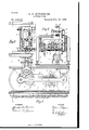
- Figure l is a broken longitudinal section of the car provided with my improved apparatus, the latter being shown in elevation.
- Fig. 2 is a vertical cross-section on the line 2 2 of Fig. 1
- Fig. 3 is a broken plan view of the lighting apparatus.
- My invention is particularly well adapted for use in connection with the railway for which I secured Letters Patent of the United States No. 538,784, dated May 7, 1895, al-
- the car is mounted on the usual wheels 11 to run on the ordinary trackrails 12, and beneath the car-floor and journaled on the axle of the car is a frame 13,'
- the gear mechanism 15 drives a vertical shaft 17, which by means of beveled gear-wheels 18 and 19 imparts motion to a shaft 2O on the frame 13, and the latter shaft by means of the beveled gear-wheels 21, 22 and 23 drives the countershaft 24, which vis journaled on the frame 13, and which connects by means of the clutchcontrolled gear-wheel 25 with a gear-wheel 26 on one of the axles 27 of the car.
- the gearing between the wheels 15 and 11 is such as to cause a differential action-that is to say, if the screw were supposed to be stationary and the car to be slid along a forward motion of fifty-one inches in the wheel 11 would produce a forward motion of, say, fifty inches at the circumference of the wheel 15, the difference of one inch being taken up by the rotation of the screw-that is, a rotation of the screw at moderate speed produces a high velocity of translation for the car, and consequently a high speed for the dynamo when the latter is in gear, as hereinafter described.
- a second frame 2S which projects upward through the carlioor, as shown clearly in Figs. 1 and 2, and this frame 2S carries an electric generator or dynamo 29, which may be of any usual kind, and which has on the armature-shaft 30 a gear-wheel 31, which is controlled by any customary form of clutch, worked by a lever 32.
- the gear-wheel 31 connects by means of meshing gears 33 and 34 with a driving-gear 35 on the counter-shaft 24, and as the counter-shaft is constantly driven by means of its gear connection with the screw 16, already described, it will be noticed that the dynamo IOO will also be constantlyL driven unless it ⁇ is thrown out of gear by the lever 32, and so the dynamo will operate equally well Whether or not the car is in motion.
- gearing may be used to drive the dynamo from the screw without departing from the 'principle of my invention, and that, if desired, a train of gearing wholly independent of anything used to propel the car may be utilized. directly on the car-door; but it is better to support it independently of the floor, so that the dynamo will not be affected bythe rise and fall of the iioor, and can, therefore, be driven without any drangement of the gearing.
- the screw-and-gear mechanism described makes a very positivemeans of driving the dynamo, and by the use of this mechanism the car may be constantly lighted and' the lights will not varyby the variation in speed of the car, as the speed of the screw is con
- the dynamo may also be supported stant, and the connection between the screw and dynamo is a positive connection.
Description
v@To Model.)
W. I'. HUTOHINSON. LIGHTING GARS.
No. 554,697. Patented Feb, 18, 1896.
l AHORA/Er.
AN DREW BLRANAM. PHOTO-IITHUVLWASNIN BTDNA) C.
I UNITED STATES PATENT GEEICE.
VILLIAM F. HUTCHINSON, OF NEW' YORK, N. Y.
LIGHTING CARS.
SPECIFICATION forming part of Letters Patent No. 554,697, dated February 18, 1896.
Application filed April 15, 1895.
To all whom it may concern:
Be it known that I, WILLIAM F. HUTCHIN- SON, of the city, county, and State of New York, have invented certain new and useful Improvements in Lighting Cars, of which the following is a full, clear, and exact description.
My invention relates to improvements in llighting cars, and particularly such cars as are propelled by a moving source of power, such as a screw along the track.
It is desirable to'light cars by electricity but it is diflcult under most circumstances, because it is ahard matter to keep the dynamo running at a desirable rate of speed during the time that the car is running and also when the car is stationary.
The objects of my invention are to produce a simple and convenient means of running an electric generator, such as a dynamo, from the source of power which propels the car and to arrange the apparatus so that the dynamo can be constantly run whether the car is in motion or not; also to arrange and support the dynamo and its driving mechanism in such a manner that the driving mechanism will not be aected by the rise and fall of the car-floor, due to the varying load of the car.
To these ends my invention consists of an apparatus for lighting cars,which will be hereinafter described and claimed.
Reference is to be had to the accompanying drawings, forming a part of this specification, in which similar figures of reference indicate corresponding parts in all the views.
Figure lis a broken longitudinal section of the car provided with my improved apparatus, the latter being shown in elevation. Fig. 2 is a vertical cross-section on the line 2 2 of Fig. 1, and Fig. 3 is a broken plan view of the lighting apparatus.
My invention is particularly well adapted for use in connection with the railway for which I secured Letters Patent of the United States No. 538,784, dated May 7, 1895, al-
though I do not confine my invention to use in connection with such special construction as the said patent shows.
Asillustrated, the car is mounted on the usual wheels 11 to run on the ordinary trackrails 12, and beneath the car-floor and journaled on the axle of the car is a frame 13,'
serial No. 545,682. or@ man.)
which supports a carriage 14, the latter carrying a gear mechanism 15, which connects with and isdriven by a revoluble screw 16, which extends along the track. The gear mechanism 15 drives a vertical shaft 17, which by means of beveled gear- wheels 18 and 19 imparts motion to a shaft 2O on the frame 13, and the latter shaft by means of the beveled gear- wheels 21, 22 and 23 drives the countershaft 24, which vis journaled on the frame 13, and which connects by means of the clutchcontrolled gear-wheel 25 with a gear-wheel 26 on one of the axles 27 of the car.
I have shown and described the foregoing mechanism in a general way only for the reason that it is like the mechanism in my former patent, referred to above, the only difference being that in the present case but one clutch-controlled gearwheel 25 is shown, whereas in practice a series of gear-wheels are used to connect the counter-shaft and axle, as illustrated in my former patent, in order that a differential speed may be 0btained.
The gearing between the wheels 15 and 11 is such as to cause a differential action-that is to say, if the screw were supposed to be stationary and the car to be slid along a forward motion of fifty-one inches in the wheel 11 would produce a forward motion of, say, fifty inches at the circumference of the wheel 15, the difference of one inch being taken up by the rotation of the screw-that is, a rotation of the screw at moderate speed produces a high velocity of translation for the car, and consequently a high speed for the dynamo when the latter is in gear, as hereinafter described.
On the frame 13 is supported a second frame 2S, which projects upward through the carlioor, as shown clearly in Figs. 1 and 2, and this frame 2S carries an electric generator or dynamo 29, which may be of any usual kind, and which has on the armature-shaft 30 a gear-wheel 31, which is controlled by any customary form of clutch, worked by a lever 32.
The gear-wheel 31 connects by means of meshing gears 33 and 34 with a driving-gear 35 on the counter-shaft 24, and as the counter-shaft is constantly driven by means of its gear connection with the screw 16, already described, it will be noticed that the dynamo IOO will also be constantlyL driven unless it `is thrown out of gear by the lever 32, and so the dynamo will operate equally well Whether or not the car is in motion.
It will be understood that other forms of gearing may be used to drive the dynamo from the screw without departing from the 'principle of my invention, and that, if desired, a train of gearing wholly independent of anything used to propel the car may be utilized. directly on the car-door; but it is better to support it independently of the floor, so that the dynamo will not be affected bythe rise and fall of the iioor, and can, therefore, be driven without any drangement of the gearing.
The screw-and-gear mechanism described makes a very positivemeans of driving the dynamo, and by the use of this mechanism the car may be constantly lighted and' the lights will not varyby the variation in speed of the car, as the speed of the screw is con The dynamo may also be supported stant, and the connection between the screw and dynamo is a positive connection.
Having thus described my invention, I
claim as new and desire to secure by Letters Patentl. The combination with the car and the revolfuble screw on the car-track, of the generator on the car, and a train of gearing connecting, the generator with the screw, substantially as described.
2. The combination with the car and the revoluble screw along the track, of the gear mechanism arranged to travel along and be driven by the screw, and an operative driv- `ing connection between the said gear mechanism and the generator, substantially as dcscribed.
WILLIAM F. I-'I'UTCHINSON lVitnesses WARREN B. HUTcHINsoN, F. W. LoNGFnLLow.
Publications (1)
| Publication Number | Publication Date |
|---|---|
| US554697A true US554697A (en) | 1896-02-18 |
Family
ID=2623435
Family Applications (1)
| Application Number | Title | Priority Date | Filing Date |
|---|---|---|---|
| US554697D Expired - Lifetime US554697A (en) | William p |
Country Status (1)
| Country | Link |
|---|---|
| US (1) | US554697A (en) |
-
0
- US US554697D patent/US554697A/en not_active Expired - Lifetime
Similar Documents
| Publication | Publication Date | Title |
|---|---|---|
| US554697A (en) | William p | |
| US818608A (en) | Suspended railway. | |
| US443768A (en) | Driving mechanism for cars on inclined railways | |
| US716285A (en) | Amusement apparatus. | |
| US659178A (en) | Electric-railway system. | |
| US538784A (en) | Railway | |
| US720291A (en) | Railway-car. | |
| US573905A (en) | Electric locomotive | |
| US1000742A (en) | Pleasure-railway. | |
| US442508A (en) | Railway-car | |
| US318717A (en) | Driving-gear for street-cars | |
| US412298A (en) | Driving-gear for cars | |
| US453025A (en) | Thirds to frederick a | |
| US1091125A (en) | Universal carriage-locomotive. | |
| US1374523A (en) | Train-lighting apparatus | |
| US572111A (en) | Combined electric and gravity pleasure-railway | |
| US551472A (en) | Traction mechanism for self-propelling vehicles | |
| US646087A (en) | Track-sweeper. | |
| US394887A (en) | Sidney howe short | |
| US425077A (en) | Electric railway-car | |
| US199762A (en) | Improvement in steam street-cars | |
| US127361A (en) | Improvement in apparatus for cleaning railway tracks | |
| US337109A (en) | Motor-car | |
| US724368A (en) | Electrical towage on canals. | |
| US576517A (en) | Self-propelling vehicle |