US554221A - Electric snap switch - Google Patents
Electric snap switch Download PDFInfo
- Publication number
- US554221A US554221A US554221DA US554221A US 554221 A US554221 A US 554221A US 554221D A US554221D A US 554221DA US 554221 A US554221 A US 554221A
- Authority
- US
- United States
- Prior art keywords
- shaft
- spring
- switch
- catch
- plate
- Prior art date
- Legal status (The legal status is an assumption and is not a legal conclusion. Google has not performed a legal analysis and makes no representation as to the accuracy of the status listed.)
- Expired - Lifetime
Links
Images

Classifications
-
- H—ELECTRICITY
- H01—ELECTRIC ELEMENTS
- H01H—ELECTRIC SWITCHES; RELAYS; SELECTORS; EMERGENCY PROTECTIVE DEVICES
- H01H19/00—Switches operated by an operating part which is rotatable about a longitudinal axis thereof and which is acted upon directly by a solid body external to the switch, e.g. by a hand
- H01H19/02—Details
- H01H19/10—Movable parts; Contacts mounted thereon
- H01H19/20—Driving mechanisms allowing angular displacement of the operating part to be effective in either direction
- H01H19/24—Driving mechanisms allowing angular displacement of the operating part to be effective in either direction acting with snap action
Definitions
- My invention relates to the class of electric switches which are actuated from a rotary shaft or spindle and operate by the winding up of a spring and the automatic-release of the catch which allows the switch-plate to be thrown by the recoil of the spring sharply out of or into contact with terminals held on a base-plate.
- the object of my invention is to provide a simple and compact switch of this class which shall be few as to the number of its parts and positive in operation; and to this end my invention consists in the details of the several parts making up the switch as a whole and in the combination of such parts, as more particularly hereinafter described and pointed out in the claims.
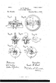
- Figure 1 is a top or plan view of the switch with cover removed.
- Fig. 2 is a view in side elevation of the switch.
- Fig. 3 is a plan view of the base, showing the socket-piece.
- Fig. 4 is a plan View, on enlarged scale,of the socket-piece and switch-plate with the shaft cut in section to illustrate the operation of the spring.
- Fig. 5 is a plan view, on enlarged scale, showing the socket-piece, and the switch-plate in position where it is thrown by the recoil of the spring.
- Fig. 6 is a detail edge view of the switch-plate.
- Fig.7 is a de tail view in elevation,on enlarged scale, showing a modified form of spring-support.
- Fig. 9 is a view in side elevation of a modified form of the switch with cover removed.
- Fig. 10 is a top or plan view of the modified form of switch.
- Fig. 11 is a detail view in vertical central section through the socket and switchplate on plane denoted by line 0c 03 of Fig. 10.
- Fig. 12 is a detail view in central section through the socket and switch-plate on the plane denoted by line y y of Fig. 10.
- Fig. 13 is a detail plan view of the switch-plate.
- Fig. 14 is a detail top view, on enlarged scale, of the stop-plate and in section through the shaft, showing the shaft in one position.
- Fig. 15 is a detail plan view, on enlarged scale, of the stop-plate and illustrating the operation of the springarm on the rotation of the shaft.
- a rotary spindle or shaft d is mounted in the baseplate and is free to turn thereon, being rotated as by means of a handle cl, preferably removably secured to the upper end of the shaft.
- a spring-actuated catch 6 is connected to the shaft in such manner that the rotary movement of the shaft winds up the spring 6 and operates to withdraw the catch e from a socket on the base-piece.
- the catch is formed preferably integral with the spiral spring wound into a helical coil, one end of the. spring being secured to the shaft d by passing it through a hole therein, while the other end extends downward, forming the specific socket-engaging part or catch 9.
- the spring as a whole is eccentric to the shaft and is attached either at the side thereof, as shown in Figs.
- a switch-plate g is loosely mounted on the shaft cl, so as to turn freely thereon, although held against movement in a direction lengthwise of the axis of the shaft.
- This switchplate is preferably of thin metal having spring-arms g forming contact-pieces which project beyond the body of the catch-plate, so as to be thrown into or out of engagement with the terminals 1) when the switch-plate is in one of the several possible positions in its rotary movement about the shaft.
- the switch-plate g has an intermittent rotary movement of such fractional part of the total revolution as may be needed to throw the contact-pieces into or hold them out of engagement with the terminals,
- My present invention is shown as embodied.
- the base-piece preferably has fast to it a socket-plate 71 in which are formed stop-shoulders h, so constructed and shaped as to hold the catch 6 against motion in any direction except by a rotary movement of the shaft.
- These steps are formed at the outer limits of cam-surfaces i that extend from the stops inward toward the shaft, being placed at such angle as will cause the catch to move toward the shaft as the latter is rotated. As soon as the catch reaches the end of such a cam it snaps over and moving forward and outward engages the next succeeding socket or stop.
- the switch-plate is located between the base-plate or socket-piece and the spring, the catch extending through a diagonal slot through the switch-plate, the general extent and location of this slot corresponding with the location, direction and extent of the camsurface, which is appurtenant to each socket in one form of the device.
- the shaft when rotated to the right, as by means of the handle, carries with it the spring into the position shown in Fig. 4 of the drawings, the catch moving inward and forward along the cam-surfaced and the slot 76.
- the spring is wound up and the catch is drawn forward and inward along the cam until the point of the cam is reached.
- the spring is not only wound up, but is revolved about the center of the shaft and moves forward, and thus in its recoil tends to sweep the catch forward and outward.
- the catch also moves along the slot in the switch plate without moving the latter until the inner point 2" of the cam is reached andthe catch free to be thrown forward and outward, so far as the socket-plate is concerned.
- the catch 6 has been drawn by this rotary movement of the shaft inward along the slot 7a in the switch-plate, and its new direction of movement under the recoil of the spring is at an angle with the position of the slot, so that the thrust of the catch against the outer wall of the slot tends to rotate the switch-plate on the shaft.
- Figs. 9 to 15, inclusive showing the modified form of the switch
- the letter a denotes the base; I)
- a socket-piece adapted to be secured to the base, as by means of the screws 5 a rotary shaft 0, having a convenienthandle forturning it being rotarily mounted in the socketpiece.
- stops Z are arranged and preferably all at the same distance from the center of the shaft.
- a switch-plate o is loosely mounted on the shaft (3 and held in any convenient manner, as by a flange 0 on the shaft 0, against lengthwise movement on the shaft,the switchplate resting immediately over the plate bearing the stops Z.
- a spring-catch 12, preferably formed of a helical spring with a projecting arm 19, is mounted on an eccentric pin or pivot q, attached to or forming part of the shaft 0, the inner end of the spring resting against the wall of the socket in which the spring is placed or being otherwise conveniently secured to the shaft in such manner as to enable the spring to be wound up or put under tension when the shaft is rotated, the outer end of the spring-arm engaging the stop until withdrawn by the continued rotary movement of the shaft and its spring with it.
- the projecting arm of the spring which terminates in the catch 7" is preferably bent upward, so as to project through the slot 0 in the switch-plate.
- the spring-arm is preferably bent close to the catch, forminga shoulder 19 which is, by the recoil of the spring, thrust against the stop in such manner as to prevent a return rotary movement of the shaft on which the spring is supported.
- the center of the pin or pivot which supports the spring is out of line with that point on the stop encountered by the shoulder and with that point of the spring which is attached to or thrusts against the wall of the springsocket, and by reason of this location of the center of the spring out of alignment with the two points stated, the spring-arm as a whole acts as a stop against return rotary movement, as stated.
- the shaft 0 is held in the socket-piece or within the base by means of any convenient device, in the form shown an annular slot 0 being provided, into which a key projects through a slot b in the wall of the socketpiece.
- any other convenient method of attaching the shaft to the socket-piece or to the base-piece, so as to provide for its free rota- IIO tion and at the same time prevent lengthwise movement of the shaft on the base-piece may be provided.
- terminal and binding-post may be provided, the terminals being arranged in the ordinary position to receive and to make contact with the switchplate when the latter is in one position of its rotary step-by-step adjustment.
- the operation of the device is substantially the same as the operation described in the first form which is illustrated in Figs. 1 to 8 of the drawings, inclusive.
- a rotary movement of the spindle carries with it the spring and causes the catch to be withdrawn'from contact with the stop, as indicated in full lines in Fig. 15 of the drawings, but by the continued rotation of the shaft the catch is finally withdrawn from the stop and then by the recoil of the spring is thrown into the position indicated in dotted outline of Fig. 15 of the drawings, and the catch encountering the next stop holds the shaft against further rotation.
- the switch-plate being loosely mounted on the shaft is not rotated with the latter, but by means of the upturned end of the'catch or of the spring-arm which engages the slot 0 in the switch-plate the latter is moved quickly forward out of or into engagement with the terminals as the spring-arm is thrown forward as soon as the catch is released from one of the stops.
- a rotary shaft mounted on a base-piece, the base with a series of stops arranged about the shaft, a spring secured to the shaft so as to turn therewith and with a resilient coil eccentric to the axis of the shaft and with an end adapted to engage the stops, a switch-plate loosely mounted on the shaft and loosely connected to the arm of the spring, all substantially as described and for the purpose specified.
- a rotary shaft mounted on a base-piece, the base-piece with terminals and a series of stops arranged about the shaft, a spring secured to the shaft so as to turn therewith and with a resilient coil adjacent to the axis of the shaft and eccentric thereof and having a catch adapted to engage the stops, a switch-plate loosely mounted on the shaft and having a slot therein receiving a projecting part of the spring-arm, all substantially as described.
- a rotary shaft mounted in a socket-piece, the socket-piece having a flange with a series of stops arranged about the shaft, a spring attached to the shaft and revolving therewith the said spring having a resilient coil eccentric to the axis of the shaft and with its outer end constituting the shoulder which engages the stops on the socket-piece, a switch-plate loosely mounted on the shaft and connected to the arm of the spring by engaging parts which permit contraction of the spring, all substantially as described.
- I11 combination in an electric snapswitch a base-piece with a series of stops arranged at intervals about its center, a rotary shaft mounted on the base-piece, a spring secured at one end to and borne by the shaft and having a catch formed integral with the spring, and a revoluble switch-plate loosely mounted on the shaft and loosely connected to the spring by the recoil of which said switchplate is turned as the shaft is rotated, all substantially as described.
Landscapes
- Rotary Switch, Piano Key Switch, And Lever Switch (AREA)
Description
(ModeL) 2 Sheets-Sheet,1. G W HART ELECTRIC SNAP SWITCH.
Patented Feb. 4, 1896.
-(Model.) 2 Sheets-Sheet 2.
W. HART. ELECTRIC SNAP SWITCH.
NO. 554,221. Patented Feb-4, 1-896.
IINTTE STATES GERALD IV. HART; OF HARTFORD, CONNECTICUT, ASSIGNOR TO THE HART & IIEGEMAN MANUFACTURING COMPANY, OF SAME PLACE.
ELECTRIC SNAP-SWITCH.
SPECIFICATION forming part of Letters Patent No. 554,221, dated February 4, 1896. Application filed $eptember 27, 1894. Serial No. 524,309. (ModeL) To all whom it may concern:
Be it known that I, GERALD \V. HART, of Hartford, in the county of Hartford and State of Connecticut, have invented certain new and useful Improvements in Electric Snap- Switches, of which the following is a full, clear, and exact description, whereby any one skilled in the art can make and use the same. My invention relates to the class of electric switches which are actuated from a rotary shaft or spindle and operate by the winding up of a spring and the automatic-release of the catch which allows the switch-plate to be thrown by the recoil of the spring sharply out of or into contact with terminals held on a base-plate.
The object of my invention is to provide a simple and compact switch of this class which shall be few as to the number of its parts and positive in operation; and to this end my invention consists in the details of the several parts making up the switch as a whole and in the combination of such parts, as more particularly hereinafter described and pointed out in the claims.
Referring to the drawings, Figure 1 is a top or plan view of the switch with cover removed. Fig. 2 is a view in side elevation of the switch. Fig. 3 is a plan view of the base, showing the socket-piece. Fig. 4 is a plan View, on enlarged scale,of the socket-piece and switch-plate with the shaft cut in section to illustrate the operation of the spring. Fig. 5 is a plan view, on enlarged scale, showing the socket-piece, and the switch-plate in position where it is thrown by the recoil of the spring. Fig. 6 is a detail edge view of the switch-plate. Fig.7 is a de tail view in elevation,on enlarged scale, showing a modified form of spring-support. Fig. Sis a detail top or plan view in section through the shaft, showing the spring in plan. Fig. 9 is a view in side elevation of a modified form of the switch with cover removed. Fig. 10 is a top or plan view of the modified form of switch. Fig. 11 is a detail view in vertical central section through the socket and switchplate on plane denoted by line 0c 03 of Fig. 10. Fig. 12 is a detail view in central section through the socket and switch-plate on the plane denoted by line y y of Fig. 10. Fig. 13 is a detail plan view of the switch-plate. Fig.
14 is a detail top view, on enlarged scale, of the stop-plate and in section through the shaft, showing the shaft in one position. Fig. 15 is a detail plan view, on enlarged scale, of the stop-plate and illustrating the operation of the springarm on the rotation of the shaft.
In the accompanying drawings the letter (t denotes the base of the switch, which may be of any suitable non-conducting material and provided with terminals 1) and binding-posts c of ordinary construction. A rotary spindle or shaft d is mounted in the baseplate and is free to turn thereon, being rotated as by means of a handle cl, preferably removably secured to the upper end of the shaft.
A spring-actuated catch 6 is connected to the shaft in such manner that the rotary movement of the shaft winds up the spring 6 and operates to withdraw the catch e from a socket on the base-piece. The catch is formed preferably integral with the spiral spring wound into a helical coil, one end of the. spring being secured to the shaft d by passing it through a hole therein, while the other end extends downward, forming the specific socket-engaging part or catch 9. The spring as a whole is eccentric to the shaft and is attached either at the side thereof, as shown in Figs. 2 and 4 of the drawings, or a shaft or may be so cut away as to enable a spring a to be wound about the remainder in such manner that the center of the spring is eccentric to the center of the shaft, as illustrated in the modified form of Figs. 7 and 8 of the drawings.
A switch-plate g is loosely mounted on the shaft cl, so as to turn freely thereon, although held against movement in a direction lengthwise of the axis of the shaft. This switchplate is preferably of thin metal having spring-arms g forming contact-pieces which project beyond the body of the catch-plate, so as to be thrown into or out of engagement with the terminals 1) when the switch-plate is in one of the several possible positions in its rotary movement about the shaft.
The switch-plate g has an intermittent rotary movement of such fractional part of the total revolution as may be needed to throw the contact-pieces into or hold them out of engagement with the terminals,
Ice
My present invention is shown as embodied.
in a single-pole switch, and the switch-plate in this structure turns one-quarter of a revolution following each release of the catch from a stop-shoulder.
The base-piece preferably has fast to it a socket-plate 71 in which are formed stop-shoulders h, so constructed and shaped as to hold the catch 6 against motion in any direction except by a rotary movement of the shaft. These steps are formed at the outer limits of cam-surfaces i that extend from the stops inward toward the shaft, being placed at such angle as will cause the catch to move toward the shaft as the latter is rotated. As soon as the catch reaches the end of such a cam it snaps over and moving forward and outward engages the next succeeding socket or stop.
The switch-plate is located between the base-plate or socket-piece and the spring, the catch extending through a diagonal slot through the switch-plate, the general extent and location of this slot corresponding with the location, direction and extent of the camsurface, which is appurtenant to each socket in one form of the device.
The operation of the device is as follows: The parts being in position, as shown in Fig. l of the drawings, the shaft when rotated to the right, as by means of the handle, carries with it the spring into the position shown in Fig. 4 of the drawings, the catch moving inward and forward along the cam-surfaced and the slot 76. By this rotary movement of the shaft the spring is wound up and the catch is drawn forward and inward along the cam until the point of the cam is reached. The spring is not only wound up, but is revolved about the center of the shaft and moves forward, and thus in its recoil tends to sweep the catch forward and outward. The catch also moves along the slot in the switch plate without moving the latter until the inner point 2" of the cam is reached andthe catch free to be thrown forward and outward, so far as the socket-plate is concerned. The catch 6 has been drawn by this rotary movement of the shaft inward along the slot 7a in the switch-plate, and its new direction of movement under the recoil of the spring is at an angle with the position of the slot, so that the thrust of the catch against the outer wall of the slot tends to rotate the switch-plate on the shaft. The outward movement of the catch under the recoil of the spring and the forward movement of the catch plate are practically simultaneous, and the movements are sharply made, so that the contact-pieces are quickly thrown into engagement or out of engagement with the terminals with a force dependent upon the strength of the spring and the quickness of its action.
The form of device above described is a preferred form for some purposes, but my in vention is not limited to the specific construction of the several parts shown in the device embodied in Figs. 1 to 8 of the drawings herein; but my invention is capable of ernbodiment in other forms equally well adapted to attain the purpose in view, and in Figs. 9 to 15 of the drawings there is shown and described a modified form of my invention, which has certain features of advantage for certain uses.
In the accompanying drawings, Figs. 9 to 15, inclusive, showing the modified form of the switch, the letter a denotes the base; I), a socket-piece adapted to be secured to the base, as by means of the screws 5 a rotary shaft 0, having a convenienthandle forturning it being rotarily mounted in the socketpiece. At convenient regular intervals about the shaft and preferably located on a flange fast to the socket piece, or forming part thereof, stops Z are arranged and preferably all at the same distance from the center of the shaft.
A switch-plate o is loosely mounted on the shaft (3 and held in any convenient manner, as by a flange 0 on the shaft 0, against lengthwise movement on the shaft,the switchplate resting immediately over the plate bearing the stops Z. A spring-catch 12, preferably formed of a helical spring with a projecting arm 19, is mounted on an eccentric pin or pivot q, attached to or forming part of the shaft 0, the inner end of the spring resting against the wall of the socket in which the spring is placed or being otherwise conveniently secured to the shaft in such manner as to enable the spring to be wound up or put under tension when the shaft is rotated, the outer end of the spring-arm engaging the stop until withdrawn by the continued rotary movement of the shaft and its spring with it.
The projecting arm of the spring which terminates in the catch 7" is preferably bent upward, so as to project through the slot 0 in the switch-plate. The spring-arm is preferably bent close to the catch, forminga shoulder 19 which is, by the recoil of the spring, thrust against the stop in such manner as to prevent a return rotary movement of the shaft on which the spring is supported. The center of the pin or pivot which supports the spring is out of line with that point on the stop encountered by the shoulder and with that point of the spring which is attached to or thrusts against the wall of the springsocket, and by reason of this location of the center of the spring out of alignment with the two points stated, the spring-arm as a whole acts as a stop against return rotary movement, as stated.
The shaft 0 is held in the socket-piece or within the base by means of any convenient device, in the form shown an annular slot 0 being provided, into which a key projects through a slot b in the wall of the socketpiece. Any other convenient method of attaching the shaft to the socket-piece or to the base-piece, so as to provide for its free rota- IIO tion and at the same time prevent lengthwise movement of the shaft on the base-piece may be provided.
Any ordinary form of terminal and binding-post may be provided, the terminals being arranged in the ordinary position to receive and to make contact with the switchplate when the latter is in one position of its rotary step-by-step adjustment.
The operation of the device is substantially the same as the operation described in the first form which is illustrated in Figs. 1 to 8 of the drawings, inclusive. A rotary movement of the spindle carries with it the spring and causes the catch to be withdrawn'from contact with the stop, as indicated in full lines in Fig. 15 of the drawings, but by the continued rotation of the shaft the catch is finally withdrawn from the stop and then by the recoil of the spring is thrown into the position indicated in dotted outline of Fig. 15 of the drawings, and the catch encountering the next stop holds the shaft against further rotation. The switch-plate being loosely mounted on the shaft is not rotated with the latter, but by means of the upturned end of the'catch or of the spring-arm which engages the slot 0 in the switch-plate the latter is moved quickly forward out of or into engagement with the terminals as the spring-arm is thrown forward as soon as the catch is released from one of the stops.
I claim as my invention.
1. In combination in a switch, a rotary shaft mounted on a base-piece, the base with a series of stops arranged about the shaft, a spring secured to the shaft so as to turn therewith and with a resilient coil eccentric to the axis of the shaft and with an end adapted to engage the stops, a switch-plate loosely mounted on the shaft and loosely connected to the arm of the spring, all substantially as described and for the purpose specified.
2. In combination in a switch, a rotary shaft mounted on a base-piece, the base-piece with terminals and a series of stops arranged about the shaft, a spring secured to the shaft so as to turn therewith and with a resilient coil adjacent to the axis of the shaft and eccentric thereof and having a catch adapted to engage the stops, a switch-plate loosely mounted on the shaft and having a slot therein receiving a projecting part of the spring-arm, all substantially as described.
3. In combination in a switch, a rotary shaft mounted in a socket-piece, the socket-piece having a flange with a series of stops arranged about the shaft, a spring attached to the shaft and revolving therewith the said spring having a resilient coil eccentric to the axis of the shaft and with its outer end constituting the shoulder which engages the stops on the socket-piece, a switch-plate loosely mounted on the shaft and connected to the arm of the spring by engaging parts which permit contraction of the spring, all substantially as described.
4. I11 combination in an electric snapswitch, a base-piece with a series of stops arranged at intervals about its center, a rotary shaft mounted on the base-piece, a spring secured at one end to and borne by the shaft and having a catch formed integral with the spring, and a revoluble switch-plate loosely mounted on the shaft and loosely connected to the spring by the recoil of which said switchplate is turned as the shaft is rotated, all substantially as described.
GERALD W. HART.
\Vitnesses:
CHAS. L. BURDETT, ARTHUR B. JENKINS.
Publications (1)
| Publication Number | Publication Date |
|---|---|
| US554221A true US554221A (en) | 1896-02-04 |
Family
ID=2622959
Family Applications (1)
| Application Number | Title | Priority Date | Filing Date |
|---|---|---|---|
| US554221D Expired - Lifetime US554221A (en) | Electric snap switch |
Country Status (1)
| Country | Link |
|---|---|
| US (1) | US554221A (en) |
Cited By (1)
| Publication number | Priority date | Publication date | Assignee | Title |
|---|---|---|---|---|
| US4390761A (en) * | 1981-01-19 | 1983-06-28 | Cole Hersee Company | High current switching |
-
0
- US US554221D patent/US554221A/en not_active Expired - Lifetime
Cited By (1)
| Publication number | Priority date | Publication date | Assignee | Title |
|---|---|---|---|---|
| US4390761A (en) * | 1981-01-19 | 1983-06-28 | Cole Hersee Company | High current switching |
Similar Documents
| Publication | Publication Date | Title |
|---|---|---|
| US554221A (en) | Electric snap switch | |
| US2534007A (en) | Switch operating mechanism with positive kickoff | |
| US1121750A (en) | Electrical-circuit-changing switch. | |
| US677269A (en) | Reversible snap-switch. | |
| US526988A (en) | Half to james f | |
| US741853A (en) | Push-button electric switch. | |
| US646146A (en) | Snap-switch. | |
| US488740A (en) | Electrical switch | |
| US1043859A (en) | Electric switch. | |
| US569332A (en) | Gerald w | |
| US994011A (en) | Snap-switch. | |
| US969581A (en) | Electric switch. | |
| US586029A (en) | Electric switch | |
| US382333A (en) | stirling | |
| USRE26118E (en) | Timer with reversible motor | |
| US496807A (en) | Hope electric | |
| US435093A (en) | Electric switch | |
| US631304A (en) | Snap-switch. | |
| US490363A (en) | Electric switch | |
| US547149A (en) | Norman marshall | |
| US981452A (en) | Electric switch. | |
| US1021208A (en) | Rotary snap-switch. | |
| US548583A (en) | Electric snap-switch | |
| US450551A (en) | Frederick adam and john knapik | |
| US563407A (en) | Charles g |