US5538109A - Piston head for an aircraft brake and insulator - Google Patents
Piston head for an aircraft brake and insulator Download PDFInfo
- Publication number
- US5538109A US5538109A US08/192,230 US19223094A US5538109A US 5538109 A US5538109 A US 5538109A US 19223094 A US19223094 A US 19223094A US 5538109 A US5538109 A US 5538109A
- Authority
- US
- United States
- Prior art keywords
- piston
- cap
- thin
- insulator
- honeycomb
- Prior art date
- Legal status (The legal status is an assumption and is not a legal conclusion. Google has not performed a legal analysis and makes no representation as to the accuracy of the status listed.)
- Expired - Fee Related
Links
Images


Classifications
-
- F—MECHANICAL ENGINEERING; LIGHTING; HEATING; WEAPONS; BLASTING
- F16—ENGINEERING ELEMENTS AND UNITS; GENERAL MEASURES FOR PRODUCING AND MAINTAINING EFFECTIVE FUNCTIONING OF MACHINES OR INSTALLATIONS; THERMAL INSULATION IN GENERAL
- F16D—COUPLINGS FOR TRANSMITTING ROTATION; CLUTCHES; BRAKES
- F16D65/00—Parts or details
- F16D65/38—Slack adjusters
- F16D65/40—Slack adjusters mechanical
- F16D65/52—Slack adjusters mechanical self-acting in one direction for adjusting excessive play
- F16D65/54—Slack adjusters mechanical self-acting in one direction for adjusting excessive play by means of direct linear adjustment
- F16D65/543—Slack adjusters mechanical self-acting in one direction for adjusting excessive play by means of direct linear adjustment comprising a plastically-deformable member
-
- F—MECHANICAL ENGINEERING; LIGHTING; HEATING; WEAPONS; BLASTING
- F16—ENGINEERING ELEMENTS AND UNITS; GENERAL MEASURES FOR PRODUCING AND MAINTAINING EFFECTIVE FUNCTIONING OF MACHINES OR INSTALLATIONS; THERMAL INSULATION IN GENERAL
- F16D—COUPLINGS FOR TRANSMITTING ROTATION; CLUTCHES; BRAKES
- F16D55/00—Brakes with substantially-radial braking surfaces pressed together in axial direction, e.g. disc brakes
- F16D55/24—Brakes with substantially-radial braking surfaces pressed together in axial direction, e.g. disc brakes with a plurality of axially-movable discs, lamellae, or pads, pressed from one side towards an axially-located member
- F16D55/26—Brakes with substantially-radial braking surfaces pressed together in axial direction, e.g. disc brakes with a plurality of axially-movable discs, lamellae, or pads, pressed from one side towards an axially-located member without self-tightening action
- F16D55/36—Brakes with a plurality of rotating discs all lying side by side
- F16D55/40—Brakes with a plurality of rotating discs all lying side by side actuated by a fluid-pressure device arranged in or one the brake
-
- F—MECHANICAL ENGINEERING; LIGHTING; HEATING; WEAPONS; BLASTING
- F16—ENGINEERING ELEMENTS AND UNITS; GENERAL MEASURES FOR PRODUCING AND MAINTAINING EFFECTIVE FUNCTIONING OF MACHINES OR INSTALLATIONS; THERMAL INSULATION IN GENERAL
- F16D—COUPLINGS FOR TRANSMITTING ROTATION; CLUTCHES; BRAKES
- F16D65/00—Parts or details
- F16D65/14—Actuating mechanisms for brakes; Means for initiating operation at a predetermined position
- F16D65/16—Actuating mechanisms for brakes; Means for initiating operation at a predetermined position arranged in or on the brake
- F16D65/18—Actuating mechanisms for brakes; Means for initiating operation at a predetermined position arranged in or on the brake adapted for drawing members together, e.g. for disc brakes
-
- B—PERFORMING OPERATIONS; TRANSPORTING
- B64—AIRCRAFT; AVIATION; COSMONAUTICS
- B64C—AEROPLANES; HELICOPTERS
- B64C25/00—Alighting gear
- B64C25/32—Alighting gear characterised by elements which contact the ground or similar surface
- B64C25/42—Arrangement or adaptation of brakes
- B64C25/44—Actuating mechanisms
-
- F—MECHANICAL ENGINEERING; LIGHTING; HEATING; WEAPONS; BLASTING
- F16—ENGINEERING ELEMENTS AND UNITS; GENERAL MEASURES FOR PRODUCING AND MAINTAINING EFFECTIVE FUNCTIONING OF MACHINES OR INSTALLATIONS; THERMAL INSULATION IN GENERAL
- F16D—COUPLINGS FOR TRANSMITTING ROTATION; CLUTCHES; BRAKES
- F16D55/00—Brakes with substantially-radial braking surfaces pressed together in axial direction, e.g. disc brakes
- F16D2055/0004—Parts or details of disc brakes
- F16D2055/0058—Fully lined, i.e. braking surface extending over the entire disc circumference
-
- F—MECHANICAL ENGINEERING; LIGHTING; HEATING; WEAPONS; BLASTING
- F16—ENGINEERING ELEMENTS AND UNITS; GENERAL MEASURES FOR PRODUCING AND MAINTAINING EFFECTIVE FUNCTIONING OF MACHINES OR INSTALLATIONS; THERMAL INSULATION IN GENERAL
- F16D—COUPLINGS FOR TRANSMITTING ROTATION; CLUTCHES; BRAKES
- F16D65/00—Parts or details
- F16D65/78—Features relating to cooling
- F16D2065/785—Heat insulation or reflection
-
- F—MECHANICAL ENGINEERING; LIGHTING; HEATING; WEAPONS; BLASTING
- F16—ENGINEERING ELEMENTS AND UNITS; GENERAL MEASURES FOR PRODUCING AND MAINTAINING EFFECTIVE FUNCTIONING OF MACHINES OR INSTALLATIONS; THERMAL INSULATION IN GENERAL
- F16D—COUPLINGS FOR TRANSMITTING ROTATION; CLUTCHES; BRAKES
- F16D2121/00—Type of actuator operation force
- F16D2121/02—Fluid pressure
-
- F—MECHANICAL ENGINEERING; LIGHTING; HEATING; WEAPONS; BLASTING
- F16—ENGINEERING ELEMENTS AND UNITS; GENERAL MEASURES FOR PRODUCING AND MAINTAINING EFFECTIVE FUNCTIONING OF MACHINES OR INSTALLATIONS; THERMAL INSULATION IN GENERAL
- F16D—COUPLINGS FOR TRANSMITTING ROTATION; CLUTCHES; BRAKES
- F16D2125/00—Components of actuators
- F16D2125/02—Fluid-pressure mechanisms
- F16D2125/06—Pistons
-
- Y—GENERAL TAGGING OF NEW TECHNOLOGICAL DEVELOPMENTS; GENERAL TAGGING OF CROSS-SECTIONAL TECHNOLOGIES SPANNING OVER SEVERAL SECTIONS OF THE IPC; TECHNICAL SUBJECTS COVERED BY FORMER USPC CROSS-REFERENCE ART COLLECTIONS [XRACs] AND DIGESTS
- Y10—TECHNICAL SUBJECTS COVERED BY FORMER USPC
- Y10T—TECHNICAL SUBJECTS COVERED BY FORMER US CLASSIFICATION
- Y10T29/00—Metal working
- Y10T29/49—Method of mechanical manufacture
- Y10T29/49229—Prime mover or fluid pump making
- Y10T29/49249—Piston making
- Y10T29/49256—Piston making with assembly or composite article making
- Y10T29/49258—Piston making with assembly or composite article making with thermal barrier or heat flow provision
-
- Y—GENERAL TAGGING OF NEW TECHNOLOGICAL DEVELOPMENTS; GENERAL TAGGING OF CROSS-SECTIONAL TECHNOLOGIES SPANNING OVER SEVERAL SECTIONS OF THE IPC; TECHNICAL SUBJECTS COVERED BY FORMER USPC CROSS-REFERENCE ART COLLECTIONS [XRACs] AND DIGESTS
- Y10—TECHNICAL SUBJECTS COVERED BY FORMER USPC
- Y10T—TECHNICAL SUBJECTS COVERED BY FORMER US CLASSIFICATION
- Y10T29/00—Metal working
- Y10T29/49—Method of mechanical manufacture
- Y10T29/49826—Assembling or joining
- Y10T29/49908—Joining by deforming
- Y10T29/49915—Overedge assembling of seated part
-
- Y—GENERAL TAGGING OF NEW TECHNOLOGICAL DEVELOPMENTS; GENERAL TAGGING OF CROSS-SECTIONAL TECHNOLOGIES SPANNING OVER SEVERAL SECTIONS OF THE IPC; TECHNICAL SUBJECTS COVERED BY FORMER USPC CROSS-REFERENCE ART COLLECTIONS [XRACs] AND DIGESTS
- Y10—TECHNICAL SUBJECTS COVERED BY FORMER USPC
- Y10T—TECHNICAL SUBJECTS COVERED BY FORMER US CLASSIFICATION
- Y10T428/00—Stock material or miscellaneous articles
- Y10T428/12—All metal or with adjacent metals
- Y10T428/1234—Honeycomb, or with grain orientation or elongated elements in defined angular relationship in respective components [e.g., parallel, inter- secting, etc.]
Definitions
- This invention relates to a friction aircraft braking system and more particularly to a new and improved piston for use in an aircraft wheel and brake assembly and to the method of making such structure.
- a plurality of alternately splined stator and rotor brake discs are brought into axial frictional engagement with each other (brake stack) generating considerable heat within such braking elements and the adjacent structures.
- the frictional energy of the braking action is converted into heat within such brake stack.
- the brake actuating elements such as the piston heads are in direct contact with the end braking disc and it is important to provide some means to limit the heat absorption to protect the brake actuating elements particularly the brake fluid which actuates the pistons.
- the piston head itself encounters the same high temperature as the braking discs and insulators are therefore used within the pistons to insulate the hydraulic actuating fluid from these high temperatures as much as possible.
- the hydraulic piston actuating fluid can expand disproportionally and cause damage to the structure.
- the heat build-up can cause an undesirable molecular structural change in the hydraulic fluid resulting in the fluid becoming corrosive and degrading its properties. This is particularly undesirable where high energy stops such as aborted take-offs occur.
- the present invention is directed to an aircraft piston structure used in a multiple disc brake assembly wherein a wheel member has axial splines engaging rotor discs which are interleaved with stator discs that are splined to a torque tube.
- the torque tube is secured to a hub and piston housing which in turn supports a plurality of pistons whose head has a thin cap supported by a honeycomb structure supported by a backup disc.
- the honeycomb wall construction and its method is such that it has excellent compressive strength to weight ratio while also providing excellent-insulating properties.
- the method employs the use of longitudinally extending metal strips that are thin in cross-section. The thin step is deformed at longitudinally spaced portions along its running length and then assembled them by joining certain of the deformed strip faces together to provide a honeycomb cell structure whose walls are extremely thin compared to the cell formed, yet provide excellent compressive strength with good insulation properties.
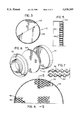
- FIG. 1 is a fragmentary cross-sectional view of an aircraft brake assembly embodying the invention as mounted in an aircraft installation;
- FIG. 2 is an enlarged cross-sectional view of a piston and cylinder assembly
- FIG. 3 is a fragmentary front elevational view of an insulator taken on line 3--3 of FIG. 2.
- FIG. 4 is fragmentary front elevational view of the insulator shown in FIG. 3 enlarged greater than the actual size of the structure to more fully disclose the honeycomb structure;
- FIG. 5 is a side elevational view in cross section of the insulator taken on line 5--5 of FIG. 4;
- FIG. 6 is an exploded view of the piston head illustrating the honeycomb insulator and the thin cap member.
- FIG. 7 is an enlarged isometric view of the honeycomb structure.
- FIG. 1 a friction brake mechanism 10 for use with a cylindrical wheel 11 having matching wheel sections 12 and 13.
- Each of the wheel sections 12 and 13 has a rim 14 and 15, web member 16 and 17, and hub members 18 and 19.
- the wheel sections 12 and 13 are fastened together by suitable bolts disposed in aligned bores within web members 16 and 17 to form an integral unit therewith.
- the hub members 18 and 19 are supported for rotation on suitable bearings which are mounted on a nonrotatable axle member 23.
- axle member 23 mounted on axle member 23 is a hub 25, which hub 25 has a radially extending flange 26 that supports a piston housing 27.
- Piston housing 27 has a plurality of circumferentially spaced bores 28 that receives cylinders 29 within which are slidably mounted pistons 30.
- Flange 26 has a plurality of circumferentially spaced bores 31 to provide means for bolts to secure a torque tube or torque tube member 32 thereto.
- Torque tube 32 has an annular and radially outwardly extending reaction plate or reaction member 33.
- the reaction plate 33 may be made integral with the torque tube member 32 or may be made as separate annular piece and suitably connected to the torque tube or torque tube member 32.
- Torque tube 32 has a plurality of circumferentially spaced splines or spline members 35 which are axially extending.
- Wheel section 12 has a plurality of circumferentially spaced ribs or splines 37 on its inner peripheral surface, which may be cast therein or may be machined to provide an integral type rib or spline for the brake assembly.
- Spline members 35 support an axially nonrotatable end disc or pressure plate 38 and inner nonrotatable discs 39, 40 and 41. All of such (stator discs) nonrotatable discs 38, 39, 40 and 41 have slotted openings at circumferentially spaced locations on the inner periphery for captive engagement by the spline members 35 as is old and well known in the art.
- Such discs 38, 39, 40 and 41 constitute the stators for friction brake 10.
- An annular disc or annular braking element 42 is suitably connected to the reaction plate 33 and acts in concert with the stator discs 38, 39, 40 and 41.
- All of the nonrotatable discs (38 through 42) and rotatable discs (44 through 47) may be made from a suitable brake material such as metal, steel or other wear-resistant material for withstanding high temperatures and providing a heat sink. The number of discs may be varied as is necessary for the application involved.
- the respective stator discs and rotor discs that have the circumferentially spaced openings on the inner and outer periphery may accommodate reinforcing inserts to provide reinforcement to the walls of such slotted openings and to enhance the life of such slots as is old and well known in the art.
- Such reinforcing inserts are also referred to as drive clips.
- Piston 30 is a cup-shaped sleeve with a rearwardly disposed end portion 49 which is suitably recessed to receive an annular seal or packing 50 which slidingly engages the interior wall surface of cylinder 29.
- the other end or front end portion of piston 30 has a piston head 51 composed of a backup disc 52, a circular honeycomb insulator 53 and a thin shield or cup-shaped cap member 54.
- the backup disc 52 is suitably connected to the sleeve portion of piston 30 which may include press fitting thereinto and being grooved to receive a retainer ring 55.
- the honeycomb insulator is made up from a plurality of stacked linear metal strips which have linear walls 48 which present a corrugated pattern, such that when two strips are placed together in the manner shown in FIG. 7, the resulting pattern discloses the honeycomb structure which permits the use of a thin metal structure, yet provide exceedingly high resistance to any deformation of load.
- the cells produced by the honeycomb structure are non-tubular or polygonal in configuration with linear wall surfaces in contrast to tubular cells such as those made from stampings which do not provide for sufficient strength or depth of the wall surfaces.
- the linear wall surfaces provide greater overall open cell area over that possible under a stamping of a sheet metal that contains circular cells which would result in greater conductivity.
- the linear walls 48 are generally parallel to the axis of the surface of the thin shield or cap member 54.
- the cup-shaped cap member or thin heat shield 54 is employed in the containment of the honeycomb 53.
- the shield 54 is thin in cross section to reduce the weight of the piston head. Thin as shown and defined herein is having little extent from one surface to its opposite surface and is particularly significant when considering the cross-sectional thickness of the cell walls and cap 54 to the height of the cell walls.
- the cell walls in their thickest section is double the wall thickness of the cap member 54 when viewed in FIG. 5. It is to be noted that FIG. 5 structural depicts the honeycomb and cap member 54 in substantially enlarged configuration to more fully illustrate the construction of the piston head. As shown in FIG.
- the cap member 54 has its peripheral edge rolled over onto the back peripheral side of the backup disc 52, thereby connecting the honeycomb insulator to the backup disc 52.
- the honeycomb insulator 53 is the sole means for transferring the forces between the brake discs (38-42 and 44-47) and the backup disc 52 (and the cylindrical sleeve portion of the piston 30).
- the peripheral edges of the thin cross-sectioned cap 54 does not transmit any forces as its lower rolled edges do not react on any member (FIG. 2) when force is applied directly from contact with the brake discs.
- each deformed strip has a corrugated pattern with linear walls 48 that are staggered or spaced in different planes.
- the first or one set of linear faces 48 are in one or a first plane while the remaining set of linear faces 48 are in a second plane which is parallel to the first plane.
- the respective lengths of the strips are dimensioned in length to assume an annular shape when joined on their flat surfaces by the use of adhesives, cement, brazing and/or welding.
- the cells produced by this process are non-tubular and have one set of end edges abutting the backup disc 52 and the other set of end edges abutting the thin shield or cup-shaped cap member 54.
- thin as referred to means it has little extent or linear dimension from one surface to its opposite surface and especially when considering its dimension to the height of the linear walls 48 of the honeycomb structure. Of particular significant in this construction is that the structure provides excellent compressive strength to weight ratio while being effective as an insulator.
- the end wall portion of cylinder 29 as shown in FIG. 2 is designated 56 and receives the enlarged head 57 of a rod 58 that extends through the rearwardly disposed end portion 49 of the piston 30.
- the other end of rod 58 has a hardened ball 60 secured thereto as by a nut for engagement with a deformable tubular member 62 which in turn is connected to tubular members 63 and 64 which are encompassed by a compression spring 65 to facilitate compensation of wear of the brake discs.
- the area between the end wall portion 56 of cylinder 29 and the rearwardly disposed end portion 49 of piston 30 define a chamber which receives pressurized fluids from a suitable pressure source via inlet conduits to move the piston 30 and the piston head 51 against the pressure plate 38 to effect a braking action of the brake stack wherein the interleaved stator and rotor discs are frictionally engaged with each other and against the end stator disc 42, which action generates a tremendous heat buildup.
- the thin heat shield or cap member 54 with its honeycomb insulator 53 and backup disc 52 effectively and efficiently provides a heat barrier for the actuating fluid behind the piston 30.
- the chamber behind piston 30 is relieved of pressure by a suitable outlet valve and conduit means to allow for the return of the piston 30 to this inoperative position.
- This thin cross-sectional thickness of the thin shield or cup-shaped cap member 54 eliminates the storing of heat energy which is expressed as a thin cross-sectioned cap wherein thin is defined as having little extent from one surface to its opposite surface.
- the honeycomb insulator has its cells with linear non-tubular walls which reduces materially the conducting area for heat transfer when compared to a honeycomb structure that is made from a stamping that defines a plurality of tubular cells. In the case of stamping a metal plate, the thickness of the punching of the bores or hole to create the cells limits substantially the length or thickness of the cells.
Landscapes
- Engineering & Computer Science (AREA)
- General Engineering & Computer Science (AREA)
- Mechanical Engineering (AREA)
- Braking Arrangements (AREA)
Abstract
Description
Claims (9)
Priority Applications (2)
| Application Number | Priority Date | Filing Date | Title |
|---|---|---|---|
| US08/192,230 US5538109A (en) | 1990-12-04 | 1994-02-04 | Piston head for an aircraft brake and insulator |
| US08/489,528 US5608967A (en) | 1990-12-04 | 1995-06-12 | Method of making piston for an aircraft brake with honeycomb insulated piston head |
Applications Claiming Priority (2)
| Application Number | Priority Date | Filing Date | Title |
|---|---|---|---|
| US62386290A | 1990-12-04 | 1990-12-04 | |
| US08/192,230 US5538109A (en) | 1990-12-04 | 1994-02-04 | Piston head for an aircraft brake and insulator |
Related Parent Applications (1)
| Application Number | Title | Priority Date | Filing Date |
|---|---|---|---|
| US62386290A Continuation-In-Part | 1990-12-04 | 1990-12-04 |
Related Child Applications (1)
| Application Number | Title | Priority Date | Filing Date |
|---|---|---|---|
| US08/489,528 Division US5608967A (en) | 1990-12-04 | 1995-06-12 | Method of making piston for an aircraft brake with honeycomb insulated piston head |
Publications (1)
| Publication Number | Publication Date |
|---|---|
| US5538109A true US5538109A (en) | 1996-07-23 |
Family
ID=26887865
Family Applications (2)
| Application Number | Title | Priority Date | Filing Date |
|---|---|---|---|
| US08/192,230 Expired - Fee Related US5538109A (en) | 1990-12-04 | 1994-02-04 | Piston head for an aircraft brake and insulator |
| US08/489,528 Expired - Fee Related US5608967A (en) | 1990-12-04 | 1995-06-12 | Method of making piston for an aircraft brake with honeycomb insulated piston head |
Family Applications After (1)
| Application Number | Title | Priority Date | Filing Date |
|---|---|---|---|
| US08/489,528 Expired - Fee Related US5608967A (en) | 1990-12-04 | 1995-06-12 | Method of making piston for an aircraft brake with honeycomb insulated piston head |
Country Status (1)
| Country | Link |
|---|---|
| US (2) | US5538109A (en) |
Cited By (17)
| Publication number | Priority date | Publication date | Assignee | Title |
|---|---|---|---|---|
| US5819882A (en) * | 1996-04-02 | 1998-10-13 | Alliedsignal Inc. | Multi-disc brake actuator for vibration damping |
| US6003954A (en) * | 1997-08-25 | 1999-12-21 | Aircraft Braking Systems Corporation | Aircraft wheel and beam key attachment |
| US6298953B1 (en) | 1996-12-12 | 2001-10-09 | Delphi Technologies, Inc. | Disc brake |
| US6318511B1 (en) * | 1998-11-25 | 2001-11-20 | Messier-Bugatti | Disk brake with high thermal resistance |
| WO2005019679A1 (en) * | 2003-08-18 | 2005-03-03 | Goodrich Corporation | Brake adjusting mechanism |
| US20050159992A1 (en) * | 2004-01-16 | 2005-07-21 | Lawrence Richard D. | Process for identifying potential customers for business outsourcing |
| US20050247529A1 (en) * | 2004-05-07 | 2005-11-10 | Gaines Louie T | Aircraft brake acuation system including an internally threaded ballscrew actuator assembly |
| US20060175155A1 (en) * | 2003-07-15 | 2006-08-10 | Knorr-Bremse Systeme Fuer Nutzfahrzeuge Gmbh | Pneumatically or electromotively operated disc brake |
| US20080142314A1 (en) * | 2006-12-14 | 2008-06-19 | Anthony Scelsi | Methods and apparatus to connect a brake disc to a brake |
| US8776956B2 (en) | 2011-01-14 | 2014-07-15 | Cwd, Llc | Brake pistons and piston noses |
| US10228030B2 (en) * | 2017-05-15 | 2019-03-12 | Goodrich Corporation | Multi-disk brake assembly with travel limit pin |
| RU193441U1 (en) * | 2019-02-13 | 2019-10-29 | Публичное акционерное общество "Авиационная корпорация "Рубин" | BRAKE WHEEL WITH HYDRAULIC BRAKE, CARBON - CARBON MONODISKS AND AIR COOLING |
| EP3611396A1 (en) * | 2018-08-13 | 2020-02-19 | Goodrich Corporation | Multi-layer thermal insulator for brake piston |
| EP3683467A1 (en) * | 2019-01-16 | 2020-07-22 | WABCO Europe BVBA | Actuating device for a utility vehicle disc brake and a disc brake for a utility vehicle |
| US20200325948A1 (en) * | 2019-04-15 | 2020-10-15 | Goodrich Corporation | Multiple layer piston insulator for hydraulic brake actuator |
| EP4289689A1 (en) * | 2022-06-06 | 2023-12-13 | Goodrich Corporation | Multi-layer aircraft brake insulator |
| US20240003395A1 (en) * | 2022-07-01 | 2024-01-04 | Goodrich Corporation | Failsafe piston pressure path |
Families Citing this family (3)
| Publication number | Priority date | Publication date | Assignee | Title |
|---|---|---|---|---|
| FR2820794A1 (en) * | 2001-02-12 | 2002-08-16 | Messier Bugatti | Transmission shaft disc braking for heavy lorries comprises set of coaxial discs with pressure structure and support structure opposite external surface of first and second end discs housed in casing filled with lubricating oil |
| DE10234642B4 (en) * | 2002-07-29 | 2020-11-05 | Knorr-Bremse Systeme für Nutzfahrzeuge GmbH | Disc brake and thermal insulation device for a disc brake |
| EP4400741A1 (en) | 2020-07-28 | 2024-07-17 | Goodrich Corporation | Piston engaging member and method of forming a piston engaging member |
Citations (12)
| Publication number | Priority date | Publication date | Assignee | Title |
|---|---|---|---|---|
| US1719215A (en) * | 1927-01-08 | 1929-07-02 | Faroy Arne | Internal-combustion engine |
| US2058741A (en) * | 1931-12-07 | 1936-10-27 | Taylor John Leonard | Insulating piston structure |
| US3995721A (en) * | 1976-03-03 | 1976-12-07 | The Bendix Corporation | Piston and extensible cylinder therefor |
| US4067670A (en) * | 1975-05-05 | 1978-01-10 | Caterpillar Tractor Co. | Internal combustion engine with insulated piston |
| US4147241A (en) * | 1977-10-27 | 1979-04-03 | The Bendix Corporation | Structurally strong heat insulator for high transient temperatures |
| US4503950A (en) * | 1983-01-27 | 1985-03-12 | Allied Corporation | Brake actuator-adjuster mechanism |
| US4531502A (en) * | 1983-05-18 | 1985-07-30 | Gte Products Corporation | Thermally insulated piston |
| US4537289A (en) * | 1982-06-18 | 1985-08-27 | International Telephone And Telegraph Corporation | Dust boot for a disc-brake actuating cylinder-and-piston unit |
| US4603760A (en) * | 1985-09-03 | 1986-08-05 | General Motors Corporation | Slotted insulator and disc brake assembly using same |
| JPS63255552A (en) * | 1987-04-11 | 1988-10-21 | Isuzu Motors Ltd | Heat insulated piston |
| US4848291A (en) * | 1987-05-30 | 1989-07-18 | Isuzu Motors Limited | Heat-insulating piston structure |
| JPH0295756A (en) * | 1988-09-30 | 1990-04-06 | Isuzu Motors Ltd | Heat insulating member for piston |
Family Cites Families (7)
| Publication number | Priority date | Publication date | Assignee | Title |
|---|---|---|---|---|
| US1857077A (en) * | 1930-11-03 | 1932-05-03 | Adamson Ernie | Internal combustion engine |
| US3435935A (en) * | 1966-09-19 | 1969-04-01 | Wichita Clutch Co Inc | Friction plate with heat dissipating material |
| DE3115740A1 (en) * | 1981-04-18 | 1982-11-04 | Daimler-Benz Ag, 7000 Stuttgart | Brake disc which can be cooled according to the principle of the heat exchanger tube |
| JPS57186899A (en) * | 1981-05-14 | 1982-11-17 | Pioneer Electronic Corp | Honey-comb core diaphragm |
| SU1153095A1 (en) * | 1984-01-02 | 1985-04-30 | Предприятие П/Я А-1877 | Piston for internal combustion engine |
| US5024369A (en) * | 1989-05-05 | 1991-06-18 | The United States Of America As Represented By The Secretary Of The Air Force | Method to produce superplastically formed titanium alloy components |
| US5107968A (en) * | 1991-02-12 | 1992-04-28 | The B. F. Goodrich Company | Heatshield for aircraft brake |
-
1994
- 1994-02-04 US US08/192,230 patent/US5538109A/en not_active Expired - Fee Related
-
1995
- 1995-06-12 US US08/489,528 patent/US5608967A/en not_active Expired - Fee Related
Patent Citations (12)
| Publication number | Priority date | Publication date | Assignee | Title |
|---|---|---|---|---|
| US1719215A (en) * | 1927-01-08 | 1929-07-02 | Faroy Arne | Internal-combustion engine |
| US2058741A (en) * | 1931-12-07 | 1936-10-27 | Taylor John Leonard | Insulating piston structure |
| US4067670A (en) * | 1975-05-05 | 1978-01-10 | Caterpillar Tractor Co. | Internal combustion engine with insulated piston |
| US3995721A (en) * | 1976-03-03 | 1976-12-07 | The Bendix Corporation | Piston and extensible cylinder therefor |
| US4147241A (en) * | 1977-10-27 | 1979-04-03 | The Bendix Corporation | Structurally strong heat insulator for high transient temperatures |
| US4537289A (en) * | 1982-06-18 | 1985-08-27 | International Telephone And Telegraph Corporation | Dust boot for a disc-brake actuating cylinder-and-piston unit |
| US4503950A (en) * | 1983-01-27 | 1985-03-12 | Allied Corporation | Brake actuator-adjuster mechanism |
| US4531502A (en) * | 1983-05-18 | 1985-07-30 | Gte Products Corporation | Thermally insulated piston |
| US4603760A (en) * | 1985-09-03 | 1986-08-05 | General Motors Corporation | Slotted insulator and disc brake assembly using same |
| JPS63255552A (en) * | 1987-04-11 | 1988-10-21 | Isuzu Motors Ltd | Heat insulated piston |
| US4848291A (en) * | 1987-05-30 | 1989-07-18 | Isuzu Motors Limited | Heat-insulating piston structure |
| JPH0295756A (en) * | 1988-09-30 | 1990-04-06 | Isuzu Motors Ltd | Heat insulating member for piston |
Cited By (23)
| Publication number | Priority date | Publication date | Assignee | Title |
|---|---|---|---|---|
| US5819882A (en) * | 1996-04-02 | 1998-10-13 | Alliedsignal Inc. | Multi-disc brake actuator for vibration damping |
| US6298953B1 (en) | 1996-12-12 | 2001-10-09 | Delphi Technologies, Inc. | Disc brake |
| US6003954A (en) * | 1997-08-25 | 1999-12-21 | Aircraft Braking Systems Corporation | Aircraft wheel and beam key attachment |
| US6318511B1 (en) * | 1998-11-25 | 2001-11-20 | Messier-Bugatti | Disk brake with high thermal resistance |
| US20060175155A1 (en) * | 2003-07-15 | 2006-08-10 | Knorr-Bremse Systeme Fuer Nutzfahrzeuge Gmbh | Pneumatically or electromotively operated disc brake |
| WO2005019679A1 (en) * | 2003-08-18 | 2005-03-03 | Goodrich Corporation | Brake adjusting mechanism |
| US20060272904A1 (en) * | 2003-08-18 | 2006-12-07 | Soellner Kenneth A | Brake adjusting mechanism |
| US20050159992A1 (en) * | 2004-01-16 | 2005-07-21 | Lawrence Richard D. | Process for identifying potential customers for business outsourcing |
| US20050247529A1 (en) * | 2004-05-07 | 2005-11-10 | Gaines Louie T | Aircraft brake acuation system including an internally threaded ballscrew actuator assembly |
| US20080142314A1 (en) * | 2006-12-14 | 2008-06-19 | Anthony Scelsi | Methods and apparatus to connect a brake disc to a brake |
| US8776956B2 (en) | 2011-01-14 | 2014-07-15 | Cwd, Llc | Brake pistons and piston noses |
| US10174840B2 (en) | 2011-01-14 | 2019-01-08 | Cwd, Llc | Brake pistons and piston noses |
| US10228030B2 (en) * | 2017-05-15 | 2019-03-12 | Goodrich Corporation | Multi-disk brake assembly with travel limit pin |
| EP3611396A1 (en) * | 2018-08-13 | 2020-02-19 | Goodrich Corporation | Multi-layer thermal insulator for brake piston |
| US10968971B2 (en) * | 2018-08-13 | 2021-04-06 | Goodrich Corporation | Multi-layer insulator for brake piston |
| EP3683467A1 (en) * | 2019-01-16 | 2020-07-22 | WABCO Europe BVBA | Actuating device for a utility vehicle disc brake and a disc brake for a utility vehicle |
| US11441627B2 (en) | 2019-01-16 | 2022-09-13 | Wabco Europe Bvba | Disc brake and brake application device for commercial vehicles |
| RU193441U1 (en) * | 2019-02-13 | 2019-10-29 | Публичное акционерное общество "Авиационная корпорация "Рубин" | BRAKE WHEEL WITH HYDRAULIC BRAKE, CARBON - CARBON MONODISKS AND AIR COOLING |
| US20200325948A1 (en) * | 2019-04-15 | 2020-10-15 | Goodrich Corporation | Multiple layer piston insulator for hydraulic brake actuator |
| US10941825B2 (en) * | 2019-04-15 | 2021-03-09 | Goodrich Corporation | Multiple layer piston insulator for hydraulic brake actuator |
| EP4289689A1 (en) * | 2022-06-06 | 2023-12-13 | Goodrich Corporation | Multi-layer aircraft brake insulator |
| US12305726B2 (en) | 2022-06-06 | 2025-05-20 | Goodrich Corporation | Multi-layer aircraft brake insulator |
| US20240003395A1 (en) * | 2022-07-01 | 2024-01-04 | Goodrich Corporation | Failsafe piston pressure path |
Also Published As
| Publication number | Publication date |
|---|---|
| US5608967A (en) | 1997-03-11 |
Similar Documents
| Publication | Publication Date | Title |
|---|---|---|
| US5538109A (en) | Piston head for an aircraft brake and insulator | |
| US4878563A (en) | Brake apparatus | |
| US3754624A (en) | Flexible key for disc brake | |
| US4147241A (en) | Structurally strong heat insulator for high transient temperatures | |
| US4585096A (en) | Brake apparatus | |
| US5107968A (en) | Heatshield for aircraft brake | |
| US5205382A (en) | Aircraft brake | |
| US10968971B2 (en) | Multi-layer insulator for brake piston | |
| US6098764A (en) | Shaft brake disk for rail vehicle disk brake systems and method of making same | |
| EP2503176B1 (en) | Heat shield installation for aircraft wheel to improve convective cooling of aircraft brake | |
| US5002342A (en) | Brake assembly heat shield | |
| JP4504657B2 (en) | Disc assembly backing plate | |
| US5199536A (en) | Heatshield installation for aircraft brake | |
| US2423882A (en) | Disk brake | |
| US3708042A (en) | Carbon core segmented friction disc | |
| EP0356793B1 (en) | Disc brake or clutch | |
| US5219046A (en) | Aircraft brake | |
| CA1211055A (en) | Brake apparatus | |
| GB2174774A (en) | A disc brake for a vehicle wheel | |
| US3747712A (en) | Friction disc for disc brake | |
| EP0020389B1 (en) | Disc brake assembly containing split discs | |
| GB2161560A (en) | Wheel and brake assembly | |
| EP0398274A1 (en) | Aircraft brake | |
| EP0480358B1 (en) | Aircraft brake | |
| GB2121140A (en) | Disc assemblies for brakes |
Legal Events
| Date | Code | Title | Description |
|---|---|---|---|
| AS | Assignment |
Owner name: B.F. GOODRICH COMPANY, THE, OHIO Free format text: ASSIGNMENT OF ASSIGNORS INTEREST;ASSIGNOR:SWANK, JOHN PHILIP;REEL/FRAME:007313/0423 Effective date: 19940606 |
|
| FEPP | Fee payment procedure |
Free format text: PAYOR NUMBER ASSIGNED (ORIGINAL EVENT CODE: ASPN); ENTITY STATUS OF PATENT OWNER: LARGE ENTITY |
|
| FPAY | Fee payment |
Year of fee payment: 4 |
|
| FEPP | Fee payment procedure |
Free format text: PAYOR NUMBER ASSIGNED (ORIGINAL EVENT CODE: ASPN); ENTITY STATUS OF PATENT OWNER: LARGE ENTITY Free format text: PAYER NUMBER DE-ASSIGNED (ORIGINAL EVENT CODE: RMPN); ENTITY STATUS OF PATENT OWNER: LARGE ENTITY |
|
| REMI | Maintenance fee reminder mailed | ||
| LAPS | Lapse for failure to pay maintenance fees | ||
| FP | Lapsed due to failure to pay maintenance fee |
Effective date: 20040723 |
|
| STCH | Information on status: patent discontinuation |
Free format text: PATENT EXPIRED DUE TO NONPAYMENT OF MAINTENANCE FEES UNDER 37 CFR 1.362 |