US5536548A - Optical recording disk - Google Patents
Optical recording disk Download PDFInfo
- Publication number
- US5536548A US5536548A US08/406,410 US40641095A US5536548A US 5536548 A US5536548 A US 5536548A US 40641095 A US40641095 A US 40641095A US 5536548 A US5536548 A US 5536548A
- Authority
- US
- United States
- Prior art keywords
- dye
- recording layer
- recording
- phthalocyanine
- groove
- Prior art date
- Legal status (The legal status is an assumption and is not a legal conclusion. Google has not performed a legal analysis and makes no representation as to the accuracy of the status listed.)
- Expired - Lifetime
Links
- 230000003287 optical effect Effects 0.000 title claims abstract description 32
- 239000000975 dye Substances 0.000 claims abstract description 90
- 239000001007 phthalocyanine dye Substances 0.000 claims abstract description 48
- 238000000354 decomposition reaction Methods 0.000 claims abstract description 32
- 239000000758 substrate Substances 0.000 claims description 30
- 239000000434 metal complex dye Substances 0.000 claims description 6
- 230000035945 sensitivity Effects 0.000 abstract description 11
- 239000010410 layer Substances 0.000 description 81
- -1 nitrosilicon phthalocyanine compound Chemical class 0.000 description 27
- 125000000217 alkyl group Chemical group 0.000 description 25
- 150000001875 compounds Chemical class 0.000 description 15
- 238000002310 reflectometry Methods 0.000 description 14
- 125000004429 atom Chemical group 0.000 description 12
- 239000002184 metal Substances 0.000 description 12
- 229910052751 metal Inorganic materials 0.000 description 12
- 239000000203 mixture Substances 0.000 description 12
- 125000003545 alkoxy group Chemical group 0.000 description 11
- 125000001997 phenyl group Chemical group [H]C1=C([H])C([H])=C(*)C([H])=C1[H] 0.000 description 10
- 125000001424 substituent group Chemical group 0.000 description 9
- 150000001450 anions Chemical class 0.000 description 8
- 125000003118 aryl group Chemical group 0.000 description 8
- 238000000034 method Methods 0.000 description 8
- 230000008901 benefit Effects 0.000 description 7
- 125000004432 carbon atom Chemical group C* 0.000 description 7
- 239000011248 coating agent Substances 0.000 description 7
- 238000000576 coating method Methods 0.000 description 7
- 229910052802 copper Inorganic materials 0.000 description 7
- 125000005843 halogen group Chemical group 0.000 description 7
- 125000002496 methyl group Chemical group [H]C([H])([H])* 0.000 description 7
- 239000011347 resin Substances 0.000 description 7
- 229920005989 resin Polymers 0.000 description 7
- 229910052759 nickel Inorganic materials 0.000 description 6
- 230000001681 protective effect Effects 0.000 description 5
- 238000002834 transmittance Methods 0.000 description 5
- 125000004104 aryloxy group Chemical group 0.000 description 4
- 230000008033 biological extinction Effects 0.000 description 4
- 239000000460 chlorine Substances 0.000 description 4
- 125000001495 ethyl group Chemical group [H]C([H])([H])C([H])([H])* 0.000 description 4
- 125000004435 hydrogen atom Chemical group [H]* 0.000 description 4
- 239000003446 ligand Substances 0.000 description 4
- IEQIEDJGQAUEQZ-UHFFFAOYSA-N phthalocyanine Chemical compound N1C(N=C2C3=CC=CC=C3C(N=C3C4=CC=CC=C4C(=N4)N3)=N2)=C(C=CC=C2)C2=C1N=C1C2=CC=CC=C2C4=N1 IEQIEDJGQAUEQZ-UHFFFAOYSA-N 0.000 description 4
- 238000002411 thermogravimetry Methods 0.000 description 4
- ZAMOUSCENKQFHK-UHFFFAOYSA-N Chlorine atom Chemical compound [Cl] ZAMOUSCENKQFHK-UHFFFAOYSA-N 0.000 description 3
- QVGXLLKOCUKJST-UHFFFAOYSA-N atomic oxygen Chemical compound [O] QVGXLLKOCUKJST-UHFFFAOYSA-N 0.000 description 3
- 125000000484 butyl group Chemical group [H]C([*])([H])C([H])([H])C([H])([H])C([H])([H])[H] 0.000 description 3
- 229910052801 chlorine Inorganic materials 0.000 description 3
- 150000004696 coordination complex Chemical class 0.000 description 3
- 229910052737 gold Inorganic materials 0.000 description 3
- 239000010931 gold Substances 0.000 description 3
- 125000004051 hexyl group Chemical group [H]C([H])([H])C([H])([H])C([H])([H])C([H])([H])C([H])([H])C([H])([H])* 0.000 description 3
- 229910052739 hydrogen Inorganic materials 0.000 description 3
- 239000001257 hydrogen Substances 0.000 description 3
- 238000004519 manufacturing process Methods 0.000 description 3
- 239000000463 material Substances 0.000 description 3
- 238000002156 mixing Methods 0.000 description 3
- 229910052760 oxygen Inorganic materials 0.000 description 3
- 239000001301 oxygen Substances 0.000 description 3
- 229910052763 palladium Inorganic materials 0.000 description 3
- 125000001436 propyl group Chemical group [H]C([*])([H])C([H])([H])C([H])([H])[H] 0.000 description 3
- 229910052710 silicon Inorganic materials 0.000 description 3
- 239000000243 solution Substances 0.000 description 3
- 125000002023 trifluoromethyl group Chemical group FC(F)(F)* 0.000 description 3
- 229920000178 Acrylic resin Polymers 0.000 description 2
- 239000004925 Acrylic resin Substances 0.000 description 2
- XKRFYHLGVUSROY-UHFFFAOYSA-N Argon Chemical compound [Ar] XKRFYHLGVUSROY-UHFFFAOYSA-N 0.000 description 2
- RTZKZFJDLAIYFH-UHFFFAOYSA-N Diethyl ether Chemical compound CCOCC RTZKZFJDLAIYFH-UHFFFAOYSA-N 0.000 description 2
- PXGOKWXKJXAPGV-UHFFFAOYSA-N Fluorine Chemical compound FF PXGOKWXKJXAPGV-UHFFFAOYSA-N 0.000 description 2
- 239000002253 acid Substances 0.000 description 2
- 125000004423 acyloxy group Chemical group 0.000 description 2
- 239000000956 alloy Substances 0.000 description 2
- 229910045601 alloy Inorganic materials 0.000 description 2
- 150000007942 carboxylates Chemical class 0.000 description 2
- 229910052804 chromium Inorganic materials 0.000 description 2
- 238000010276 construction Methods 0.000 description 2
- SWXVUIWOUIDPGS-UHFFFAOYSA-N diacetone alcohol Chemical compound CC(=O)CC(C)(C)O SWXVUIWOUIDPGS-UHFFFAOYSA-N 0.000 description 2
- 238000000113 differential scanning calorimetry Methods 0.000 description 2
- 238000004455 differential thermal analysis Methods 0.000 description 2
- 229910052731 fluorine Inorganic materials 0.000 description 2
- 239000011737 fluorine Substances 0.000 description 2
- 229910052736 halogen Inorganic materials 0.000 description 2
- 150000002367 halogens Chemical class 0.000 description 2
- 125000000623 heterocyclic group Chemical group 0.000 description 2
- 238000001746 injection moulding Methods 0.000 description 2
- 229910052742 iron Inorganic materials 0.000 description 2
- 229910052744 lithium Inorganic materials 0.000 description 2
- 229910052748 manganese Inorganic materials 0.000 description 2
- 238000005259 measurement Methods 0.000 description 2
- 238000012986 modification Methods 0.000 description 2
- 230000004048 modification Effects 0.000 description 2
- 125000001624 naphthyl group Chemical group 0.000 description 2
- 230000000802 nitrating effect Effects 0.000 description 2
- 125000001147 pentyl group Chemical group C(CCCC)* 0.000 description 2
- 229910052697 platinum Inorganic materials 0.000 description 2
- 229920005668 polycarbonate resin Polymers 0.000 description 2
- 239000004431 polycarbonate resin Substances 0.000 description 2
- 125000002924 primary amino group Chemical group [H]N([H])* 0.000 description 2
- 229910052709 silver Inorganic materials 0.000 description 2
- 239000002904 solvent Substances 0.000 description 2
- 238000004528 spin coating Methods 0.000 description 2
- ANRHNWWPFJCPAZ-UHFFFAOYSA-M thionine Chemical compound [Cl-].C1=CC(N)=CC2=[S+]C3=CC(N)=CC=C3N=C21 ANRHNWWPFJCPAZ-UHFFFAOYSA-M 0.000 description 2
- 229910052719 titanium Inorganic materials 0.000 description 2
- 229910052720 vanadium Inorganic materials 0.000 description 2
- 229910052725 zinc Inorganic materials 0.000 description 2
- 229910052726 zirconium Inorganic materials 0.000 description 2
- ORIHZIZPTZTNCU-VMPITWQZSA-N 2-[(E)-hydroxyiminomethyl]phenol Chemical compound O\N=C\C1=CC=CC=C1O ORIHZIZPTZTNCU-VMPITWQZSA-N 0.000 description 1
- ZNQVEEAIQZEUHB-UHFFFAOYSA-N 2-ethoxyethanol Chemical compound CCOCCO ZNQVEEAIQZEUHB-UHFFFAOYSA-N 0.000 description 1
- 125000004180 3-fluorophenyl group Chemical group [H]C1=C([H])C(*)=C([H])C(F)=C1[H] 0.000 description 1
- 125000004207 3-methoxyphenyl group Chemical group [H]C1=C([H])C(*)=C([H])C(OC([H])([H])[H])=C1[H] 0.000 description 1
- ZCYVEMRRCGMTRW-UHFFFAOYSA-N 7553-56-2 Chemical compound [I] ZCYVEMRRCGMTRW-UHFFFAOYSA-N 0.000 description 1
- WKBOTKDWSSQWDR-UHFFFAOYSA-N Bromine atom Chemical compound [Br] WKBOTKDWSSQWDR-UHFFFAOYSA-N 0.000 description 1
- SNRUBQQJIBEYMU-UHFFFAOYSA-N Dodecane Natural products CCCCCCCCCCCC SNRUBQQJIBEYMU-UHFFFAOYSA-N 0.000 description 1
- LFQSCWFLJHTTHZ-UHFFFAOYSA-N Ethanol Chemical compound CCO LFQSCWFLJHTTHZ-UHFFFAOYSA-N 0.000 description 1
- UFHFLCQGNIYNRP-UHFFFAOYSA-N Hydrogen Chemical group [H][H] UFHFLCQGNIYNRP-UHFFFAOYSA-N 0.000 description 1
- 101150108015 STR6 gene Proteins 0.000 description 1
- 101100386054 Saccharomyces cerevisiae (strain ATCC 204508 / S288c) CYS3 gene Proteins 0.000 description 1
- 125000005595 acetylacetonate group Chemical group 0.000 description 1
- 125000003668 acetyloxy group Chemical group [H]C([H])([H])C(=O)O[*] 0.000 description 1
- 150000001298 alcohols Chemical class 0.000 description 1
- 125000004414 alkyl thio group Chemical group 0.000 description 1
- 229910052782 aluminium Inorganic materials 0.000 description 1
- 125000004397 aminosulfonyl group Chemical group NS(=O)(=O)* 0.000 description 1
- 239000000010 aprotic solvent Substances 0.000 description 1
- 229910052786 argon Inorganic materials 0.000 description 1
- 239000012300 argon atmosphere Substances 0.000 description 1
- 125000005110 aryl thio group Chemical group 0.000 description 1
- 239000012298 atmosphere Substances 0.000 description 1
- 229910052788 barium Inorganic materials 0.000 description 1
- 239000011230 binding agent Substances 0.000 description 1
- 230000015572 biosynthetic process Effects 0.000 description 1
- GDTBXPJZTBHREO-UHFFFAOYSA-N bromine Substances BrBr GDTBXPJZTBHREO-UHFFFAOYSA-N 0.000 description 1
- 229910052794 bromium Inorganic materials 0.000 description 1
- 229910052793 cadmium Inorganic materials 0.000 description 1
- 229910052791 calcium Inorganic materials 0.000 description 1
- 125000002837 carbocyclic group Chemical group 0.000 description 1
- 239000013522 chelant Substances 0.000 description 1
- 150000004697 chelate complex Chemical class 0.000 description 1
- 239000003795 chemical substances by application Substances 0.000 description 1
- 229910001914 chlorine tetroxide Inorganic materials 0.000 description 1
- 238000007796 conventional method Methods 0.000 description 1
- 239000010949 copper Substances 0.000 description 1
- 239000013078 crystal Substances 0.000 description 1
- 238000013500 data storage Methods 0.000 description 1
- 238000000151 deposition Methods 0.000 description 1
- 230000008021 deposition Effects 0.000 description 1
- 238000013461 design Methods 0.000 description 1
- 150000004662 dithiols Chemical class 0.000 description 1
- 125000003438 dodecyl group Chemical group [H]C([H])([H])C([H])([H])C([H])([H])C([H])([H])C([H])([H])C([H])([H])C([H])([H])C([H])([H])C([H])([H])C([H])([H])C([H])([H])C([H])([H])* 0.000 description 1
- 150000002148 esters Chemical class 0.000 description 1
- 230000008020 evaporation Effects 0.000 description 1
- 238000001704 evaporation Methods 0.000 description 1
- 125000001153 fluoro group Chemical group F* 0.000 description 1
- 229910052732 germanium Inorganic materials 0.000 description 1
- 239000011521 glass Substances 0.000 description 1
- PCHJSUWPFVWCPO-UHFFFAOYSA-N gold Chemical compound [Au] PCHJSUWPFVWCPO-UHFFFAOYSA-N 0.000 description 1
- 238000010438 heat treatment Methods 0.000 description 1
- 125000006343 heptafluoro propyl group Chemical group 0.000 description 1
- 125000001183 hydrocarbyl group Chemical group 0.000 description 1
- 125000002887 hydroxy group Chemical group [H]O* 0.000 description 1
- 229910052738 indium Inorganic materials 0.000 description 1
- 239000011261 inert gas Substances 0.000 description 1
- 239000011630 iodine Substances 0.000 description 1
- 229910052740 iodine Inorganic materials 0.000 description 1
- 229910052741 iridium Inorganic materials 0.000 description 1
- 125000001449 isopropyl group Chemical group [H]C([H])([H])C([H])(*)C([H])([H])[H] 0.000 description 1
- 150000002576 ketones Chemical class 0.000 description 1
- 229910052745 lead Inorganic materials 0.000 description 1
- 125000000040 m-tolyl group Chemical group [H]C1=C([H])C(*)=C([H])C(=C1[H])C([H])([H])[H] 0.000 description 1
- 229910052749 magnesium Inorganic materials 0.000 description 1
- 239000000155 melt Substances 0.000 description 1
- 229910052750 molybdenum Inorganic materials 0.000 description 1
- 238000000465 moulding Methods 0.000 description 1
- LKKPNUDVOYAOBB-UHFFFAOYSA-N naphthalocyanine Chemical compound N1C(N=C2C3=CC4=CC=CC=C4C=C3C(N=C3C4=CC5=CC=CC=C5C=C4C(=N4)N3)=N2)=C(C=C2C(C=CC=C2)=C2)C2=C1N=C1C2=CC3=CC=CC=C3C=C2C4=N1 LKKPNUDVOYAOBB-UHFFFAOYSA-N 0.000 description 1
- 125000001971 neopentyl group Chemical group [H]C([*])([H])C(C([H])([H])[H])(C([H])([H])[H])C([H])([H])[H] 0.000 description 1
- 230000007935 neutral effect Effects 0.000 description 1
- 229910052758 niobium Inorganic materials 0.000 description 1
- 125000000449 nitro group Chemical group [O-][N+](*)=O 0.000 description 1
- RIFHPKDYLRBSGB-UHFFFAOYSA-N nitrosilicon Chemical compound [O-][N+]([Si])=O RIFHPKDYLRBSGB-UHFFFAOYSA-N 0.000 description 1
- 238000001579 optical reflectometry Methods 0.000 description 1
- 239000003960 organic solvent Substances 0.000 description 1
- 229910052762 osmium Inorganic materials 0.000 description 1
- 125000006340 pentafluoro ethyl group Chemical group FC(F)(F)C(F)(F)* 0.000 description 1
- 125000000538 pentafluorophenyl group Chemical group FC1=C(F)C(F)=C(*)C(F)=C1F 0.000 description 1
- VLTRZXGMWDSKGL-UHFFFAOYSA-M perchlorate Chemical compound [O-]Cl(=O)(=O)=O VLTRZXGMWDSKGL-UHFFFAOYSA-M 0.000 description 1
- 230000000737 periodic effect Effects 0.000 description 1
- 229920000515 polycarbonate Polymers 0.000 description 1
- 239000004417 polycarbonate Substances 0.000 description 1
- 229920000728 polyester Polymers 0.000 description 1
- 238000006116 polymerization reaction Methods 0.000 description 1
- 229920000098 polyolefin Polymers 0.000 description 1
- 229910052700 potassium Inorganic materials 0.000 description 1
- 238000002360 preparation method Methods 0.000 description 1
- 238000012545 processing Methods 0.000 description 1
- 239000011241 protective layer Substances 0.000 description 1
- 125000000168 pyrrolyl group Chemical group 0.000 description 1
- 230000005855 radiation Effects 0.000 description 1
- 229910052703 rhodium Inorganic materials 0.000 description 1
- 229910052707 ruthenium Inorganic materials 0.000 description 1
- 150000003839 salts Chemical class 0.000 description 1
- 239000004065 semiconductor Substances 0.000 description 1
- 239000010944 silver (metal) Substances 0.000 description 1
- 229910052708 sodium Inorganic materials 0.000 description 1
- 238000004544 sputter deposition Methods 0.000 description 1
- 101150035983 str1 gene Proteins 0.000 description 1
- 239000000126 substance Substances 0.000 description 1
- 125000005415 substituted alkoxy group Chemical group 0.000 description 1
- 125000000547 substituted alkyl group Chemical group 0.000 description 1
- 125000001273 sulfonato group Chemical group [O-]S(*)(=O)=O 0.000 description 1
- 238000003786 synthesis reaction Methods 0.000 description 1
- 229910052715 tantalum Inorganic materials 0.000 description 1
- 229910052713 technetium Inorganic materials 0.000 description 1
- 125000000999 tert-butyl group Chemical group [H]C([H])([H])C(*)(C([H])([H])[H])C([H])([H])[H] 0.000 description 1
- 229910052716 thallium Inorganic materials 0.000 description 1
- 238000002076 thermal analysis method Methods 0.000 description 1
- 229920005992 thermoplastic resin Polymers 0.000 description 1
- 229910052718 tin Inorganic materials 0.000 description 1
- 230000000699 topical effect Effects 0.000 description 1
- 125000003866 trichloromethyl group Chemical group ClC(Cl)(Cl)* 0.000 description 1
- 125000005034 trifluormethylthio group Chemical group FC(S*)(F)F 0.000 description 1
- 229910052721 tungsten Inorganic materials 0.000 description 1
- 238000009827 uniform distribution Methods 0.000 description 1
- 229910052724 xenon Inorganic materials 0.000 description 1
- FHNFHKCVQCLJFQ-UHFFFAOYSA-N xenon atom Chemical compound [Xe] FHNFHKCVQCLJFQ-UHFFFAOYSA-N 0.000 description 1
Images
Classifications
-
- G—PHYSICS
- G11—INFORMATION STORAGE
- G11B—INFORMATION STORAGE BASED ON RELATIVE MOVEMENT BETWEEN RECORD CARRIER AND TRANSDUCER
- G11B7/00—Recording or reproducing by optical means, e.g. recording using a thermal beam of optical radiation by modifying optical properties or the physical structure, reproducing using an optical beam at lower power by sensing optical properties; Record carriers therefor
- G11B7/24—Record carriers characterised by shape, structure or physical properties, or by the selection of the material
- G11B7/241—Record carriers characterised by shape, structure or physical properties, or by the selection of the material characterised by the selection of the material
- G11B7/252—Record carriers characterised by shape, structure or physical properties, or by the selection of the material characterised by the selection of the material of layers other than recording layers
- G11B7/258—Record carriers characterised by shape, structure or physical properties, or by the selection of the material characterised by the selection of the material of layers other than recording layers of reflective layers
-
- G—PHYSICS
- G11—INFORMATION STORAGE
- G11B—INFORMATION STORAGE BASED ON RELATIVE MOVEMENT BETWEEN RECORD CARRIER AND TRANSDUCER
- G11B7/00—Recording or reproducing by optical means, e.g. recording using a thermal beam of optical radiation by modifying optical properties or the physical structure, reproducing using an optical beam at lower power by sensing optical properties; Record carriers therefor
- G11B7/24—Record carriers characterised by shape, structure or physical properties, or by the selection of the material
- G11B7/241—Record carriers characterised by shape, structure or physical properties, or by the selection of the material characterised by the selection of the material
- G11B7/242—Record carriers characterised by shape, structure or physical properties, or by the selection of the material characterised by the selection of the material of recording layers
- G11B7/244—Record carriers characterised by shape, structure or physical properties, or by the selection of the material characterised by the selection of the material of recording layers comprising organic materials only
- G11B7/246—Record carriers characterised by shape, structure or physical properties, or by the selection of the material characterised by the selection of the material of recording layers comprising organic materials only containing dyes
- G11B7/247—Record carriers characterised by shape, structure or physical properties, or by the selection of the material characterised by the selection of the material of recording layers comprising organic materials only containing dyes methine or polymethine dyes
- G11B7/2472—Record carriers characterised by shape, structure or physical properties, or by the selection of the material characterised by the selection of the material of recording layers comprising organic materials only containing dyes methine or polymethine dyes cyanine
-
- G—PHYSICS
- G11—INFORMATION STORAGE
- G11B—INFORMATION STORAGE BASED ON RELATIVE MOVEMENT BETWEEN RECORD CARRIER AND TRANSDUCER
- G11B7/00—Recording or reproducing by optical means, e.g. recording using a thermal beam of optical radiation by modifying optical properties or the physical structure, reproducing using an optical beam at lower power by sensing optical properties; Record carriers therefor
- G11B7/24—Record carriers characterised by shape, structure or physical properties, or by the selection of the material
- G11B7/241—Record carriers characterised by shape, structure or physical properties, or by the selection of the material characterised by the selection of the material
- G11B7/242—Record carriers characterised by shape, structure or physical properties, or by the selection of the material characterised by the selection of the material of recording layers
- G11B7/244—Record carriers characterised by shape, structure or physical properties, or by the selection of the material characterised by the selection of the material of recording layers comprising organic materials only
- G11B7/246—Record carriers characterised by shape, structure or physical properties, or by the selection of the material characterised by the selection of the material of recording layers comprising organic materials only containing dyes
- G11B7/248—Record carriers characterised by shape, structure or physical properties, or by the selection of the material characterised by the selection of the material of recording layers comprising organic materials only containing dyes porphines; azaporphines, e.g. phthalocyanines
-
- G—PHYSICS
- G11—INFORMATION STORAGE
- G11B—INFORMATION STORAGE BASED ON RELATIVE MOVEMENT BETWEEN RECORD CARRIER AND TRANSDUCER
- G11B7/00—Recording or reproducing by optical means, e.g. recording using a thermal beam of optical radiation by modifying optical properties or the physical structure, reproducing using an optical beam at lower power by sensing optical properties; Record carriers therefor
- G11B7/24—Record carriers characterised by shape, structure or physical properties, or by the selection of the material
- G11B7/241—Record carriers characterised by shape, structure or physical properties, or by the selection of the material characterised by the selection of the material
- G11B7/242—Record carriers characterised by shape, structure or physical properties, or by the selection of the material characterised by the selection of the material of recording layers
- G11B7/244—Record carriers characterised by shape, structure or physical properties, or by the selection of the material characterised by the selection of the material of recording layers comprising organic materials only
- G11B7/249—Record carriers characterised by shape, structure or physical properties, or by the selection of the material characterised by the selection of the material of recording layers comprising organic materials only containing organometallic compounds
-
- G—PHYSICS
- G11—INFORMATION STORAGE
- G11B—INFORMATION STORAGE BASED ON RELATIVE MOVEMENT BETWEEN RECORD CARRIER AND TRANSDUCER
- G11B7/00—Recording or reproducing by optical means, e.g. recording using a thermal beam of optical radiation by modifying optical properties or the physical structure, reproducing using an optical beam at lower power by sensing optical properties; Record carriers therefor
- G11B7/24—Record carriers characterised by shape, structure or physical properties, or by the selection of the material
- G11B7/241—Record carriers characterised by shape, structure or physical properties, or by the selection of the material characterised by the selection of the material
- G11B7/242—Record carriers characterised by shape, structure or physical properties, or by the selection of the material characterised by the selection of the material of recording layers
- G11B7/244—Record carriers characterised by shape, structure or physical properties, or by the selection of the material characterised by the selection of the material of recording layers comprising organic materials only
- G11B7/246—Record carriers characterised by shape, structure or physical properties, or by the selection of the material characterised by the selection of the material of recording layers comprising organic materials only containing dyes
- G11B2007/24612—Record carriers characterised by shape, structure or physical properties, or by the selection of the material characterised by the selection of the material of recording layers comprising organic materials only containing dyes two or more dyes in one layer
-
- G—PHYSICS
- G11—INFORMATION STORAGE
- G11B—INFORMATION STORAGE BASED ON RELATIVE MOVEMENT BETWEEN RECORD CARRIER AND TRANSDUCER
- G11B7/00—Recording or reproducing by optical means, e.g. recording using a thermal beam of optical radiation by modifying optical properties or the physical structure, reproducing using an optical beam at lower power by sensing optical properties; Record carriers therefor
- G11B7/24—Record carriers characterised by shape, structure or physical properties, or by the selection of the material
- G11B7/241—Record carriers characterised by shape, structure or physical properties, or by the selection of the material characterised by the selection of the material
- G11B7/252—Record carriers characterised by shape, structure or physical properties, or by the selection of the material characterised by the selection of the material of layers other than recording layers
- G11B7/253—Record carriers characterised by shape, structure or physical properties, or by the selection of the material characterised by the selection of the material of layers other than recording layers of substrates
- G11B7/2533—Record carriers characterised by shape, structure or physical properties, or by the selection of the material characterised by the selection of the material of layers other than recording layers of substrates comprising resins
- G11B7/2534—Record carriers characterised by shape, structure or physical properties, or by the selection of the material characterised by the selection of the material of layers other than recording layers of substrates comprising resins polycarbonates [PC]
-
- G—PHYSICS
- G11—INFORMATION STORAGE
- G11B—INFORMATION STORAGE BASED ON RELATIVE MOVEMENT BETWEEN RECORD CARRIER AND TRANSDUCER
- G11B7/00—Recording or reproducing by optical means, e.g. recording using a thermal beam of optical radiation by modifying optical properties or the physical structure, reproducing using an optical beam at lower power by sensing optical properties; Record carriers therefor
- G11B7/24—Record carriers characterised by shape, structure or physical properties, or by the selection of the material
- G11B7/241—Record carriers characterised by shape, structure or physical properties, or by the selection of the material characterised by the selection of the material
- G11B7/252—Record carriers characterised by shape, structure or physical properties, or by the selection of the material characterised by the selection of the material of layers other than recording layers
- G11B7/254—Record carriers characterised by shape, structure or physical properties, or by the selection of the material characterised by the selection of the material of layers other than recording layers of protective topcoat layers
- G11B7/2542—Record carriers characterised by shape, structure or physical properties, or by the selection of the material characterised by the selection of the material of layers other than recording layers of protective topcoat layers consisting essentially of organic resins
-
- G—PHYSICS
- G11—INFORMATION STORAGE
- G11B—INFORMATION STORAGE BASED ON RELATIVE MOVEMENT BETWEEN RECORD CARRIER AND TRANSDUCER
- G11B7/00—Recording or reproducing by optical means, e.g. recording using a thermal beam of optical radiation by modifying optical properties or the physical structure, reproducing using an optical beam at lower power by sensing optical properties; Record carriers therefor
- G11B7/24—Record carriers characterised by shape, structure or physical properties, or by the selection of the material
- G11B7/241—Record carriers characterised by shape, structure or physical properties, or by the selection of the material characterised by the selection of the material
- G11B7/252—Record carriers characterised by shape, structure or physical properties, or by the selection of the material characterised by the selection of the material of layers other than recording layers
- G11B7/258—Record carriers characterised by shape, structure or physical properties, or by the selection of the material characterised by the selection of the material of layers other than recording layers of reflective layers
- G11B7/2595—Record carriers characterised by shape, structure or physical properties, or by the selection of the material characterised by the selection of the material of layers other than recording layers of reflective layers based on gold
-
- Y—GENERAL TAGGING OF NEW TECHNOLOGICAL DEVELOPMENTS; GENERAL TAGGING OF CROSS-SECTIONAL TECHNOLOGIES SPANNING OVER SEVERAL SECTIONS OF THE IPC; TECHNICAL SUBJECTS COVERED BY FORMER USPC CROSS-REFERENCE ART COLLECTIONS [XRACs] AND DIGESTS
- Y10—TECHNICAL SUBJECTS COVERED BY FORMER USPC
- Y10S—TECHNICAL SUBJECTS COVERED BY FORMER USPC CROSS-REFERENCE ART COLLECTIONS [XRACs] AND DIGESTS
- Y10S428/00—Stock material or miscellaneous articles
- Y10S428/913—Material designed to be responsive to temperature, light, moisture
-
- Y—GENERAL TAGGING OF NEW TECHNOLOGICAL DEVELOPMENTS; GENERAL TAGGING OF CROSS-SECTIONAL TECHNOLOGIES SPANNING OVER SEVERAL SECTIONS OF THE IPC; TECHNICAL SUBJECTS COVERED BY FORMER USPC CROSS-REFERENCE ART COLLECTIONS [XRACs] AND DIGESTS
- Y10—TECHNICAL SUBJECTS COVERED BY FORMER USPC
- Y10S—TECHNICAL SUBJECTS COVERED BY FORMER USPC CROSS-REFERENCE ART COLLECTIONS [XRACs] AND DIGESTS
- Y10S430/00—Radiation imagery chemistry: process, composition, or product thereof
- Y10S430/146—Laser beam
-
- Y—GENERAL TAGGING OF NEW TECHNOLOGICAL DEVELOPMENTS; GENERAL TAGGING OF CROSS-SECTIONAL TECHNOLOGIES SPANNING OVER SEVERAL SECTIONS OF THE IPC; TECHNICAL SUBJECTS COVERED BY FORMER USPC CROSS-REFERENCE ART COLLECTIONS [XRACs] AND DIGESTS
- Y10—TECHNICAL SUBJECTS COVERED BY FORMER USPC
- Y10T—TECHNICAL SUBJECTS COVERED BY FORMER US CLASSIFICATION
- Y10T428/00—Stock material or miscellaneous articles
- Y10T428/21—Circular sheet or circular blank
Definitions
- This invention relates to an optical recording disk having a dye film as a recording layer, and more particularly, to an optical recording disk of the write-once type using a phthalocyanine dye.
- Optical recording disks of the write-once, rewritable and other types have been of great interest as high capacity information carrying media.
- Some optical recording disks use a dye film as the recording layer.
- commonly used optical recording disks are classified into the air-sandwich structure having an air space on a dye base recording layer and the close contact type having a reflective layer in close contact with a dye base recording layer.
- the latter has the advantage that they can be reproduced in accordance with the compact disk (CD) standard.
- CD compact disk
- the substrate is formed with a spiral groove at a pitch of about 1.6 ⁇ m for tracking.
- the region of the recording layer in the groove serves as a recording track.
- cyanine dyes were predominant in the prior art. However, the cyanine dyes are generally less resistant to light and insufficiently reliable on recording. Attempts are thus made to use phthalocyanine dyes instead.
- the phthalocyanine dyes however, have the problem of low recording sensitivity when used in the recording layer because they are generally thermally stable.
- JP-A Japanese Patent Application Kokai
- JP-A Japanese Patent Application Kokai
- R 1 and R 2 are alkyl, aryl, alkoxyl or aryloxy groups.
- a nitrosilicon phthalocyanine compound of a specific structure having a selected type of substituent must be used.
- Some compounds are not commercially available and must be synthesized through a process which is cumbersome to the disk manufacturers. Even if synthesis is possible, some compounds are difficult to synthesize or low in yield.
- a primary object of the present invention is to provide an optical recording disk using a stable phthalocyanine dye in the recording layer and affording an improved recording sensitivity.
- an optical recording disk comprising a substrate having a groove for tracking, a dye-containing recording layer on the substrate, and a reflective layer on the recording layer, wherein recording light is directed to the recording layer in the groove to form a recorded spot.
- the recording layer containing at least one phthalocyanine dye and at least one second dye having a lower heat decomposition temperature than said phthalocyanine dye.
- the second dye is preferably a phthalocyanine dye, an indolenine-cyanine dye or a metal complex dye, with the indolenine-cyanine dye being especially preferred.
- the phthalocyanine dye and the second dye are preferably mixed in a weight ratio of from 85:15 to 25:75.
- the groove has a depth of 800 to 1,700 ⁇ and a width of 0.3 to 0.6 ⁇ m and the recording layer in the groove has a thickness of 1,500 to 2,500 ⁇ .
- FIG. 1 is a schematic cross-sectional view of a portion of an optical recording disk according to the present invention.
- the optical recording disk of the present invention has a recording layer which contains at least one phthalocyanine dye and at least one second dye having a lower heat decomposition temperature than the phthalocyanine dye.
- the first phthalocyanine dye is often referred to as phthalocyanine dye A and the second dye is referred to as dye B, hereinafter.
- dye A thermally stable phthalocyanine dye
- a thermally stable phthalocyanine dye (dye A) has a high heat decomposition temperature when used alone, a mixture of dyes A and B combined has a lower heat decomposition temperature. That is, mixing of two dyes A and B brings out a depression of heat decomposition temperature. Consequently, recording sensitivity is improved and recording can be done with a lower power.
- recording sensitivity is improved to a level comparable to or greater than the recording sensitivity available with the conventional indolenine-cyanine dyes.
- the optimum recording power can be reduced by about 20 to 40% as compared with the sole use of a phthalocyanine dye.
- JP-A 255339/1993 discloses the use of at least one nitro group-containing silicon phthalocyanine compound of a specific structure in the recording layer. However, only one is used in Examples and no discussion is made as to the use of a mixture of phthalocyanine compounds. The heat decomposition temperature of dyes is referred to nowhere. This patent reference is different in construction from the present invention.
- the recording layer of a specific dye combination in the disk according to the invention has a heat decomposition temperature which is lower than that of a recording layer consisting solely of a phthalocyanine dye and generally ranges from about 240° C. to about 300° C.
- phthalocyanine dye A used herein has a heat decomposition temperature Td 1 of about 410° to 430° C.
- One phthalocyanine dye is normally used although a plurality of phthalocyanine dyes having an identical heat decomposition temperature may be used as dye A.
- the second dye to be combined with phthalocyanine dye A and having a lower heat decomposition temperature than phthalocyanine dye A, that is, dye B has a heat decomposition temperature Td 2 (Td 2 ⁇ Td 1 ) of preferably about 120° to 300° C.
- Dye B is preferably selected from the group consisting of a phthalocyanine dye, an indolenine-cyanine dye, and a metal complex dye. Better results are obtained by using an indolenine-cyanine dye as dye B when the solubility of a dye in an organic solvent as a coating medium is taken into account.
- One dye is normally used although a plurality of dyes may be used as dye B.
- phthalocyanine dyes used herein include naphthalocyanine dyes as well as phthalocyanine dyes.
- the difference in heat decomposition temperature between phthalocyanine dye A and dye B, that is, (Td 1 -Td 2 ) is about 100° to 300° C.
- the recording layer preferably contains phthalocyanine dye A and dye B in a weight ratio of from 85:15 to 25:75, more preferably from 75:25 to 25:75, further preferably from 70:30 to 30:70, most preferably from 60:40 to 40:60. Blending ratios within this range ensure a sufficient depression of heat decomposition temperature to achieve the benefits of the invention. Higher contents of phthalocyanine dye A exceeding the range would fail to provide a sufficient depression of heat decomposition temperature. Inversely, higher contents of dye B exceeding the range would tend to somewhat raise the heat decomposition temperature, also failing to achieve the benefits of the invention.
- dye B is a dye other than the phthalocyanine dye, for example, an indolenine-cyanine dye
- a dye mixture as a whole would not take full advantage of the characteristics, for example, light resistance of the phthalocyanine dye as dye A.
- the recording layer is formed solely of dyes although it may contain another component such as a resin binder.
- the heat decomposition temperature is the temperature at which a dye or recording layer is decomposed by heat and can be determined by thermal analysis such as thermo-gravimetric analysis (TG), differential thermal analysis (DTA) and differential scanning calorimetric analysis (DSC).
- the heat decomposition temperature of a recording layer is defined as the heat decomposition temperature of a dye mixture of the same composition as the recording layer. Measurement of a heat decomposition temperature is carried out in an inert gas atmosphere such as argon in order to eliminate the influence of oxygen in air.
- phthalocyanine dye A used herein is selected from phthalocyanine dyes of the following general formula (1). ##STR1##
- each of Q 1 , Q 2 , Q 3 , and Q 4 is a group of atoms necessary to complete a benzene ring or naphthalene ring; each of R 1 , R 2 , R 3 , and R 4 is a monovalent substituent; M 1 is a center atom; Y 1 is a ligand which can coordinate with the center atom; letters p, q, r, and s each are 0, 1 or 2; letters t, u, v, and w each are 0, 1 or 2; and letter m is 0, 1 or 2.
- the condensed ring represented by Q 1 , Q 2 , Q 3 , and Q 4 as being condensed to the pyrrole ring is preferably a benzene ring.
- R 1 , R 2 , R 3 , and R 4 Included in the monovalent substituents represented by R 1 , R 2 , R 3 , and R 4 are halogen atoms such as chlorine, bromine, iodine and fluorine atoms; substituted or unsubstituted alkyl groups such as methyl, ethyl, hexyl, dodecyl, isopropyl, 2-ethylhexyl, t-butyl, neopentyl, trichloromethyl, 1,2-dichloroethyl, trifluoromethyl, pentafluoroethyl, 1,1,2,2-tetrafluoroethyl, heptafluoropropyl, and 2,2,3,3-tetrafluoropropyl groups; substituted or unsubstituted aryl groups such as phenyl, naphthyl, 3-methylphenyl, 3-methoxyphenyl, 3-
- Preferred substituents are alkyl and alkoxy groups.
- alkyl groups substituted alkyl groups having 1 to 12 carbon atoms are preferred which may be normal or branched.
- Substituents on the alkyl groups are preferably halogen atoms such as fluorine.
- alkoxy groups substituted alkoxy groups having 1 to 12 carbon atoms are preferred while their alkyl moiety may be normal or branched.
- Substituents on the alkoxy groups are preferably halogen atoms such as fluorine.
- R 1 to R 4 are identical in most cases although they may be different if desired.
- M 1 Included in the center atoms represented by M 1 are hydrogen atoms (2H) and metal atoms.
- the metal atom are metal atoms belonging to Groups 1 to 14 of the Periodic Table (Groups 1A to 7A, 8, and 1B to 4B), such as Li, Na, K, Mg, Ca, Ba, Ti, Zr, V, Nb, Ta, Cr, Mo, W, Mn, Tc, Fe, Co, Ni, Ru, Rh, Pd, Os, Ir, Pt, Cu, Ag, Au, Zn, Cd, Hg, Al, In, Tl, Si, Ge, Sn, and Pb.
- Preferred among these are Li, Ti, V, Cr, Mn, Fe, Co, Ni, Cu, Zn, Al, and Si, with Si being most preferred.
- the ligand represented by Y 1 includes hydrogen, oxygen, halogen, hydroxyl, alkyl, alkoxy, acyloxy, and a group represented by the following formula (2): ##STR2## wherein each of R 5 and R 6 , which may be identical or different, is an alkyl, aryl, alkoxy or aryloxy group.
- examples of the halogen atom, alkyl and alkoxy groups represented by Y 1 and the alkyl, aryl, alkoxy and aryloxy groups represented by R 5 and R 6 are the same as exemplified for R 1 to R 4 .
- examples of the acyloxy group represented by Y 1 are acetoxy and propionyloxy groups.
- the preferred ligand represented by Y 1 is a group of formula (2) wherein each of R 5 and R 6 is typically a substituted or unsubstituted alkyl group having 1 to 6 carbon atoms or an aryl group such as phenyl.
- R 1 , R 2 , R 3 , R 4 , p, q, r, s, t, u, v and w are the same as defined in formula (1), with preferred examples being the same.
- R 5 and R 6 are the same as defined in formula (2), with preferred examples being the same.
- R 5 groups or R 6 groups or R 5 and R 6 groups are identical in most cases while they may be different if desired.
- phthalocyanine compounds of formula (1) can be synthesized by a well-known process. Nitro-substituted ones may be synthesized by nitrating a corresponding well-known nitro-free phthalocyanine compound in an aprotic solvent with a nitrating agent as described in JP-A 255339/1993. Several phthalocyanine compounds are commercially available in a state ready for use.
- Dye B having a lower heat decomposition temperature than phthalocyanine dye A is preferably an indolenine-cyanine dye, especially of the following general formula (4). ##STR4##
- each of R 1 and R 2 is a hydrocarbon group, especially an alkyl group.
- the alkyl groups may be either substituted or unsubstituted. Preferred are alkyl groups having 1 to 10 carbon atoms, such as methyl, ethyl, propyl, butyl, pentyl, and hexyl groups. Substituents on the alkyl groups include halogen, alkyl, aryl, alkoxy, amino, heterocyclic, carboxylate and sulfonate groups.
- R 1 and R 2 may be identical or different. More preferably R 1 and R 2 are unsubstituted alkyl groups.
- R 3 and R 4 is a monovalent group, for example, substituted or unsubstituted alkyl, aryl, alkoxy, amino and heterocyclic groups and halogen atoms. If possible, these monovalent groups may have a substituent which is the same as exemplified for R 1 and R 2 .
- Letters p1 and q1 each are 0 or an integer of 1 to 4. Where each of p1 and q1 is an integer of 2 to 4, adjoining R 3 groups or adjoining R 4 groups, taken together, may form a ring which is preferably carbocyclic, especially a benzene ring.
- X is a counter anion.
- Letter m1 is a number necessary to neutralize an electric charge, which depends on the type of R 1 to R 4 .
- m1 is equal to 0 when an inner salt is formed as given by the combination that R 1 is a carboxylate or sulfonate-substituted alkyl group and R 2 , R 3 , and R 4 are electrically neutral groups.
- Preferred among the indolenine-cyanine dyes of formula (4) are the following combinations of R 1 to R 4 , p1 and q1.
- R 1 , R 2 unsubstituted alkyl groups having 1 to 6 carbon atoms, e.g., methyl, ethyl, propyl, butyl, pentyl and hexyl groups.
- Both p1 and q1 are 2 and adjoining R 3 groups or adjoining R 4 groups, taken together, form a benzene ring (the benzene ring is preferably condensed at 4- and 5-positions).
- indolenine-cyanine dyes of formula (4) are those of the following general formula (5). ##STR5##
- R 1 , R 2 , X and m1 are as defined for formula (4).
- R 31 is a hydrogen atom, halogen atom or alkyl group. Chlorine is a typical halogen atom. Preferred examples of the alkyl group are unsubstituted alkyl groups having 1 to 4 carbon atoms such as methyl, ethyl, propyl and butyl groups. Preferably R 31 is hydrogen, chlorine or methyl.
- the counter anion X in formulae (4) and (5) is selected from conventional acid anions and metal complex quencher anions, with the latter being preferred.
- metal complex quencher anions examples include those of acetylacetonato systems, bisdithiol systems such as bisdithio- ⁇ -diketone and bisphenylenedithiol systems, thiocatechol systems, salicylaldehydeoxime systems, and thiobisphenolate systems.
- metal complex quencher anions of the bisphenylenedithiol system which are desirably represented by the following general formula (6). ##STR6##
- M 1 is a center metal, for example, Ni, Cu, Co, Pd, and Pt, with Ni and Cu being preferred.
- Letter n is an integer of 1 to 10, especially 4.
- Examples of the acid anion include halide ions (e.g., Cl - , Br - and I - ), ClO 4 - , BF 4 - , PF 6 - , VO 3 - , VO 4 3- , WO 4 2- , CH 3 SO 3 - , CF 3 COO - , CH 3 COO - , HSO 4 - , CF 3 SO 3 - , PO 4 .12WO 3 3- , p-toluenesulfonate ion (PTS - ), and p-trifluoromethylphenylsulfonate ion (PFS - ).
- halide ions e.g., Cl - , Br - and I -
- ClO 4 - e.g., Cl - , Br - and I -
- BF 4 - e.g., PF 6 -
- VO 3 - e.g.,
- indolenine-cyanine dye of formula (5) are shown in Table 2 as combinations of R 1 , R 2 , R 31 , X and m1.
- dye B is a phthalocyanine dye (other than dye A) which is desirably of the following general formula (7). ##STR7##
- M is a center atom, for example, hydrogen and metal atoms as exemplified in formula (1).
- Preferred examples of the metal atom include Cu, Si, Ni, Co, Pd, and Zr, with Pd being most preferred.
- Each of R 11 , R 12 , R 13 and R 14 is a monovalent substituent group.
- Each of letters a, b, c and d is 0 or an integer of 1 to 4, preferably 1 or 2.
- Examples of the monovalent group represented by R 11 to R 14 include sulfamoyl, nitro, azo and alkyl groups. Among these, branched alkyl groups having 3 to 10 carbon atoms are preferred, with unsubstituted ones being especially preferred.
- R 11 to R 14 may be identical or different although they are generally identical.
- dye B is a metal complex dye which is desirably selected from dithiol metal complexes, indoaniline metal complexes, and azomethine chelate complexes having Ni as a center metal.
- the optical recording disk of the invention has a dye base recording layer and a reflective layer in close contact therewith and is capable of reproduction in accordance with the CD standard.
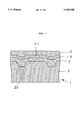
- the optical recording disk 1 includes a substrate 2 having front and rear surfaces (upper and lower surfaces in the FIGURE) and a groove 23 in the front surface.
- the optical recording disk 1 is shown in FIG. 1 as comprising a dye base recording layer 3 on the front surface of the grooved substrate 2, a reflective layer 4 disposed on the surface of the recording layer 3 in close contact, and a protective layer 5 disposed on the surface of the reflective layer 4. Recording and reproducing light is directed to the recording layer 3 within the groove 23 from the rear surface side of the substrate 2.
- the substrate 2 is of conventional disk shape and has commonly used dimensions, for example, a thickness of about 1.2 mm and a diameter of about 80 to 120 mm when the disk is intended for a recordable CD.
- the substrate 2 is formed of a resin or glass material which is substantially transparent to recording and reading light, typically a semiconductor laser beam having a wavelength of 600 to 900 nm, especially 770 to 800 nm, most often 780 nm.
- the substrate material preferably has a transmittance of at least 88% so that recording and reading operation can be made through the substrate 2, that is, from the rear surface of the substrate 2 remote from the recording layer 3.
- the substrate 2 is formed of resins, typically thermoplastic resins such as polycarbonate resin, acrylic resins, amorphous polyolefins, and TPX using conventional techniques such as injection molding.
- a groove 23 is formed for tracking purposes.
- the tracking groove 23 is preferably a continuous spiral groove wherein adjoining groove turns are separated by a land 21.
- the groove has a depth of 800 to 1,700 ⁇ , more preferably 1,000 to 1,500 ⁇ (depth is a distance from the land 21 to the groove 23 bottom) and a width of 0.3 to 0.6 ⁇ m, more preferably 0.4 to 0.5 ⁇ m (width is a distance in a radial direction with respect to the disk center).
- the adjoining groove turns are preferably arranged at a pitch of 1.5 to 1.7 ⁇ m.
- the groove is preferably formed at the same time as molding of the substrate 2.
- a resin layer (not shown) having a predetermined pattern including grooves may be formed on the substrate by 2P (photo-polymerization) method or the like.
- the groove is formed in the substrate 2 surface, a provision is preferably made such that recording light may be directed to a recording layer within the groove 23. That is, the optical recording disk of the invention is preferably used as an optical recording medium of the groove recording type. The groove recording permits the recording layer to have a greater effective thickness.
- the groove having the above-defined depth and width ensures improved writing and reading properties. Ease of processing is another advantage.
- a groove depth greater than the above-defined range would result in lower reflectivity.
- a groove depth less than the above-defined range would result in a lower recording sensitivity and a lower radial contrast before recording.
- a groove width greater than the above-defined range would result in increased crosstalk, that is, interference between radially adjoining pits, more frequent occurrence of record signal waveform distortion, more jitter and more errors.
- a groove with a width less than the above-defined range is difficult to process.
- the recording layer 3 is formed on the grooved substrate 2 using a mixture of the first and second dyes A and B.
- the recording layer 3 preferably has a coefficient of extinction (the imaginary part of a complex index of refraction) k of from 0.02 to 0.05 at the wavelength of recording and reading light. With k ⁇ 0.02, the recording layer can have a lower absorptivity so that it might become difficult to record with a commonly used power. A coefficient of extinction k of more than 0.05 can result in a drop of reflectivity to below 70%, often failing to reproduce according to the CD standard.
- the recording layer preferably has an index of refraction (the real part of a complex index of refraction) n of from 2.0 to 2.6 at the wavelength of recording and reading light. With n ⁇ 2.0, the reflectivity and signal outputs would be reduced, often failing to read by CD players. Few dyes have n>2.6.
- a sample is prepared by forming a recording layer on a given transparent substrate to a thickness of about 40 to 100 nm under practical conditions. Then the reflectivity of the sample is measured through the substrate or from the recording layer side. Reflectivity is measured in a specular reflection mode (of the order of 5°) using light having the recording/reproducing wavelength. The transmittance of the sample is also measured. The index of refraction n and coefficient of extinction k may be calculated from these measurements according to Ishiguro Kozo, "Optics," Kyoritsu Publishing K.K., pages 168-178. Also n and k of a dye are determined by forming a dye film and measuring the parameters of the dye film as above.
- That region of the recording layer 3 within the groove 23 becomes a recording track.
- the (tracking) region of the recording layer 3 within the groove 23 preferably has a thickness of 1,000 to 3,000 ⁇ , more preferably 1,500 to 2,500 ⁇ . Within this thickness range, a sufficient degree of modulation is expectable. If the recording layer is too thin within the groove, there would be available a lower degree of modulation.
- That region of the recording layer 3 above the land 21 (between the grooves 23) has a thickness of about 800 to 1,700 ⁇ , especially 1,000 to 1,500 ⁇ . On average, the recording layer 3 has a thickness of about 1,250 to 2,000 ⁇ .
- the thickness of the recording layer 3 on the groove and land is controlled within the above-defined range, reflectivity is enhanced to ensure reproduction in accordance with the CD standard. If the recording layer 3 is thinner, reflectivity is reduced to make it difficult to ensure reproduction in accordance with the CD standard.
- the recording layer 3 may be formed by any desired process. Coating is recommended because greater margins are afforded with respect to a choice of dyes, medium design, a degree of freedom during manufacture, and ease of manufacture.
- various solvents may be used including ketone, ester, ether, aromatic, halogenated alkyl, alcohol, and cellosolve solvents. Spin coating is a preferred coating technique.
- the reflective layer 4 is formed directly on the recording layer 3 in close contact therewith.
- the reflective layer 4 may be constructed by a high reflectivity metal or alloy such as Au, Ag, Cu or alloys thereof. It preferably has a thickness of at least 500 ⁇ and may be formed by evaporation or sputtering. The upper limit of thickness is not critical although it is about 1,200 ⁇ or less when cost and production time are taken into account.
- the reflective layer alone has a reflectivity of at least 90%, and the reflectivity of an unrecorded portion of an optical recording disk through the substrate can be at least 60%, especially at least 70%. Such high reflectivity enables reproduction in accordance with the CD standard. Reading light may have a power of about 0.1 to 1.0 mW.
- the protective film 5 is formed on the reflective layer 4.
- the protective film 5 is formed of various resins such as UV-curable resins to a thickness of about 0.5 to 30 ⁇ m, especially about 1 to 10 ⁇ m.
- the protective film 5 may be a layer to be deposited or a preformed sheet to be applied onto the reflective layer 4.
- the protective film 5 is formed by coating a composition containing a radiation-curable compound and a photopolymerization sensitizer and curing the coating with radiation. It preferably has a hardness of H to 8H, especially 2H to 7H according to the pencil hardness scale at 25° C. (JIS K-5400).
- Recording or additional recording may be carried out on the optical recording disk 1 of the above-described construction by directing recording light having a wavelength of 780 nm, for example, in pulse form to the recording layer 3 in the groove 23 through the substrate 2 to form an irradiated or recorded spot whose optical reflectivity has changed.
- the recording layer 3 absorbs light so that it is heated while the substrate 2 is heated at the same time.
- the recording material typically dyes melts or decomposes near the interface between the substrate 2 and the recording layer 3, probably applying a pressure to the interface to deform the bottom and side walls of the groove 23.
- the disk is rotated at a linear velocity of about 1.2 to 1.4 m/s.
- An optical recording disk sample as shown in FIG. 1 was prepared by injection molding a polycarbonate resin into a substrate having a diameter of 120 mm and a thickness of 1.2 mm.
- the substrate included in its recording layer-bearing surface a continuous spiral tracking groove having a pitch of 1.6 ⁇ m, a width of 0.42 ⁇ m and a depth of 1,550 ⁇ .
- a mixture of a phthalocyanine dye A and an indolenine-cyanine dye B was spin coated to form a recording layer.
- the phthalocyanine dye A used herein was compound No. 3-1 of formula (3) shown in Table 1 and the indolenine-cyanine dye B used herein was compound No. 4-1 of formula (4) shown in Table 2.
- CD signals were recorded in the optical recording disks at a wavelength of 780 nm to determine the optimum recording power. On recording, the disk was rotated at a linear velocity of 1.4 m/s.
- the recording layer was measured for heat decomposition temperature (Td) by thermogravimetric analysis. More particularly, the heat decomposition temperature was measured by mixing dye crystals in a ratio corresponding to the dye composition of the recording layer, forming a sample of uniform distribution, and heating the sample in an argon atmosphere so as to avoid any influence of oxygen. Dyes A and B were independently measured for Td by thermogravimetric analysis. Dyes A and B had a Td of 419.7° C. and 260.2° C., respectively. The results are shown in Table 4.
- sample Nos. 2 to 7 bare samples prior to deposition of the reflective layer were tested for light resistance by determining a dye retentivity.
- the percent dye retentivity was determined by measuring an initial transmittance T 0 of a recording layer-coated sample, exposing the sample to a xenon lamp at 80,000 lux for 40 hours, measuring a transmittance T of the exposed sample, and calculating in accordance with (100-T)/(100-T 0 ) ⁇ 100%.
- a dye retentivity of 90% or more was regarded acceptable with respect to light resistance.
- Sample Nos. 2 to 6 were acceptable whereas sample No. 7 was unacceptable with respect to light resistance.
- sample Nos. 2 to 6 were measured for reflectivity at 780 nm. They all had a reflectivity of higher than 65% which is sufficient to enable reading in accordance with the CD standard.
- dye A and dye B metal complex dye
- Sample Nos. 35 and 36 were similarly prepared except that the weight ratio of dye A/B was 50/50 and 0/100.
- an optical recording disk having a recording layer consisting essentially of a phthalocyanine dye A having a heat decomposition temperature Td 1 and a second dye B having a heat decomposition temperature Td 2 wherein Td 1 >Td 2 .
- the recording layer is improved in recording sensitivity while maintaining the stability or light resistance inherent to the phthalocyanine dye A.
Landscapes
- Chemical & Material Sciences (AREA)
- Organic Chemistry (AREA)
- Optical Record Carriers And Manufacture Thereof (AREA)
- Thermal Transfer Or Thermal Recording In General (AREA)
Abstract
In an optical recording disk comprising a reflective layer in close contact with a recording layer, the recording layer contains a phthalocyanine dye and a second dye having a lower heat decomposition temperature than the phthalocyanine dye. By virtue of a depression of heat decomposition temperature, recording sensitivity is improved.
Description
1. Field of the Invention
This invention relates to an optical recording disk having a dye film as a recording layer, and more particularly, to an optical recording disk of the write-once type using a phthalocyanine dye.
2. Prior Art
Optical recording disks of the write-once, rewritable and other types have been of great interest as high capacity information carrying media. Some optical recording disks use a dye film as the recording layer. From a structural aspect, commonly used optical recording disks are classified into the air-sandwich structure having an air space on a dye base recording layer and the close contact type having a reflective layer in close contact with a dye base recording layer. The latter has the advantage that they can be reproduced in accordance with the compact disk (CD) standard. In this regard, reference is made to Nikkei Electronics, Jan. 23, 1989, No. 465, page 107; the Functional Dye Department of the Kinki Chemical Society, Mar. 3, 1989, Osaka Science & Technology Center; and Proceedings SPIE--The International Society for Optical Engineering, Vol. 1078, pages 80-87, "Optical Data Storage Topical Meeting", 17-19, January 1989, Los Angels.
In the close contact structure having a reflective layer in close contact with a recording layer, the substrate is formed with a spiral groove at a pitch of about 1.6 μm for tracking. The region of the recording layer in the groove serves as a recording track.
Among the dyes used in the recording layer, cyanine dyes were predominant in the prior art. However, the cyanine dyes are generally less resistant to light and insufficiently reliable on recording. Attempts are thus made to use phthalocyanine dyes instead. The phthalocyanine dyes, however, have the problem of low recording sensitivity when used in the recording layer because they are generally thermally stable.
One solution is proposed by Japanese Patent Application Kokai (JP-A) No. 255339/1993 which discloses the use of a nitrosilicon phthalocyanine having --OP(═O)(R1)(R2) ligands coordinated above and below a center atom Si wherein R1 and R2 are alkyl, aryl, alkoxyl or aryloxy groups. In order to provide high recording sensitivity, a nitrosilicon phthalocyanine compound of a specific structure having a selected type of substituent must be used. Some compounds are not commercially available and must be synthesized through a process which is cumbersome to the disk manufacturers. Even if synthesis is possible, some compounds are difficult to synthesize or low in yield.
It is also contemplated to increase recording sensitivity by modifying the shape of a groove in the substrate. Actually attempting such shape modification, we found that the problem could not be solved when phthalocyanine dyes were used as the recording layer.
Therefore, it is desired to find a simple means for improving the recording sensitivity of an optical recording disk using a phthalocyanine dye in the recording layer.
A primary object of the present invention is to provide an optical recording disk using a stable phthalocyanine dye in the recording layer and affording an improved recording sensitivity.
Quite unexpectedly, we have found that when a phthalocyanine dye having a heat decomposition temperature Td1 is mixed with a second dye having a heat decomposition temperature Td2 which is lower than Td1, a depression of heat decomposition temperature occurs, that is, the resulting dye mixture has a heat decomposition temperature which is lower than Td1 and often lower than Td2.
According to the invention, there is provided an optical recording disk comprising a substrate having a groove for tracking, a dye-containing recording layer on the substrate, and a reflective layer on the recording layer, wherein recording light is directed to the recording layer in the groove to form a recorded spot. The recording layer containing at least one phthalocyanine dye and at least one second dye having a lower heat decomposition temperature than said phthalocyanine dye. The second dye is preferably a phthalocyanine dye, an indolenine-cyanine dye or a metal complex dye, with the indolenine-cyanine dye being especially preferred. The phthalocyanine dye and the second dye are preferably mixed in a weight ratio of from 85:15 to 25:75. In one preferred embodiment, the groove has a depth of 800 to 1,700 Å and a width of 0.3 to 0.6 μm and the recording layer in the groove has a thickness of 1,500 to 2,500 Å.
The only FIGURE, FIG. 1 is a schematic cross-sectional view of a portion of an optical recording disk according to the present invention.
The optical recording disk of the present invention has a recording layer which contains at least one phthalocyanine dye and at least one second dye having a lower heat decomposition temperature than the phthalocyanine dye. For brevity's sake, the first phthalocyanine dye is often referred to as phthalocyanine dye A and the second dye is referred to as dye B, hereinafter. Although a thermally stable phthalocyanine dye (dye A) has a high heat decomposition temperature when used alone, a mixture of dyes A and B combined has a lower heat decomposition temperature. That is, mixing of two dyes A and B brings out a depression of heat decomposition temperature. Consequently, recording sensitivity is improved and recording can be done with a lower power. More particularly, recording sensitivity is improved to a level comparable to or greater than the recording sensitivity available with the conventional indolenine-cyanine dyes. This allows phthalocyanine dyes to exert their advantage that they are significantly stable in terms of light resistance and the like. The optimum recording power can be reduced by about 20 to 40% as compared with the sole use of a phthalocyanine dye.
JP-A 255339/1993 discloses the use of at least one nitro group-containing silicon phthalocyanine compound of a specific structure in the recording layer. However, only one is used in Examples and no discussion is made as to the use of a mixture of phthalocyanine compounds. The heat decomposition temperature of dyes is referred to nowhere. This patent reference is different in construction from the present invention.
The recording layer of a specific dye combination in the disk according to the invention has a heat decomposition temperature which is lower than that of a recording layer consisting solely of a phthalocyanine dye and generally ranges from about 240° C. to about 300° C.
More particularly, phthalocyanine dye A used herein has a heat decomposition temperature Td1 of about 410° to 430° C. One phthalocyanine dye is normally used although a plurality of phthalocyanine dyes having an identical heat decomposition temperature may be used as dye A. The second dye to be combined with phthalocyanine dye A and having a lower heat decomposition temperature than phthalocyanine dye A, that is, dye B has a heat decomposition temperature Td2 (Td2 <Td1) of preferably about 120° to 300° C. Dye B is preferably selected from the group consisting of a phthalocyanine dye, an indolenine-cyanine dye, and a metal complex dye. Better results are obtained by using an indolenine-cyanine dye as dye B when the solubility of a dye in an organic solvent as a coating medium is taken into account. One dye is normally used although a plurality of dyes may be used as dye B.
It is noted that the phthalocyanine dyes used herein include naphthalocyanine dyes as well as phthalocyanine dyes.
Preferably, the difference in heat decomposition temperature between phthalocyanine dye A and dye B, that is, (Td1 -Td2) is about 100° to 300° C.
The recording layer preferably contains phthalocyanine dye A and dye B in a weight ratio of from 85:15 to 25:75, more preferably from 75:25 to 25:75, further preferably from 70:30 to 30:70, most preferably from 60:40 to 40:60. Blending ratios within this range ensure a sufficient depression of heat decomposition temperature to achieve the benefits of the invention. Higher contents of phthalocyanine dye A exceeding the range would fail to provide a sufficient depression of heat decomposition temperature. Inversely, higher contents of dye B exceeding the range would tend to somewhat raise the heat decomposition temperature, also failing to achieve the benefits of the invention. Additionally where dye B is a dye other than the phthalocyanine dye, for example, an indolenine-cyanine dye, a dye mixture as a whole would not take full advantage of the characteristics, for example, light resistance of the phthalocyanine dye as dye A.
Preferably the recording layer is formed solely of dyes although it may contain another component such as a resin binder.
The heat decomposition temperature is the temperature at which a dye or recording layer is decomposed by heat and can be determined by thermal analysis such as thermo-gravimetric analysis (TG), differential thermal analysis (DTA) and differential scanning calorimetric analysis (DSC). The heat decomposition temperature of a recording layer is defined as the heat decomposition temperature of a dye mixture of the same composition as the recording layer. Measurement of a heat decomposition temperature is carried out in an inert gas atmosphere such as argon in order to eliminate the influence of oxygen in air.
Preferably phthalocyanine dye A used herein is selected from phthalocyanine dyes of the following general formula (1). ##STR1##
In formula (1), each of Q1, Q2, Q3, and Q4 is a group of atoms necessary to complete a benzene ring or naphthalene ring; each of R1, R2, R3, and R4 is a monovalent substituent; M1 is a center atom; Y1 is a ligand which can coordinate with the center atom; letters p, q, r, and s each are 0, 1 or 2; letters t, u, v, and w each are 0, 1 or 2; and letter m is 0, 1 or 2.
The condensed ring represented by Q1, Q2, Q3, and Q4 as being condensed to the pyrrole ring is preferably a benzene ring.
Included in the monovalent substituents represented by R1, R2, R3, and R4 are halogen atoms such as chlorine, bromine, iodine and fluorine atoms; substituted or unsubstituted alkyl groups such as methyl, ethyl, hexyl, dodecyl, isopropyl, 2-ethylhexyl, t-butyl, neopentyl, trichloromethyl, 1,2-dichloroethyl, trifluoromethyl, pentafluoroethyl, 1,1,2,2-tetrafluoroethyl, heptafluoropropyl, and 2,2,3,3-tetrafluoropropyl groups; substituted or unsubstituted aryl groups such as phenyl, naphthyl, 3-methylphenyl, 3-methoxyphenyl, 3-fluorophenyl, 3-trichloromethylphenyl, 3-trifluoromethylphenyl, pentafluorophenyl, and 3-nitrophenyl groups; substituted or unsubstituted alkoxy groups such as methoxy, ethoxy, n-butoxy, tert-butoxy, 2-ethylhexyloxy, neopentoxy, 2,2,2-trichloroethoxy, 2,2,2-trifluoroethoxy, 2,2,3,3-tetrafluoropropoxy, 2,2,3,3,3-pentafluoropropoxy, 1,1,1,3,3,3-hexafluoro-2-propoxy, 2,2,3,4,4,4-hexafluorobutoxy, 1H,1H,5H-octafluoropentoxy, 1H,1H,7H-dodecafluoroheptoxy, 1H,1H,9H-hexadecafluorononyloxy, 2-(perfluorohexyl)ethoxy, 2-(perfluorooctyl)ethoxy, 2-(perfluorodecyl)ethoxy, 2-(perfluoro-3-methylbutyl)ethoxy, 6-(perfluoroethyl)hexyloxy, and 6-(perfluorohexyl)hexyloxy groups; substituted or unsubstituted aryloxy groups such as phenoxy, p-nitrophenoxy, p-tert-butylphenoxy, 3-fluorophenoxy, pentafluorophenoxy, and 3-trifluoromethylphenoxy groups; substituted or unsubstituted alkylthio groups such as methylthio, ethylthio, tert-butylthio, hexylthio, octylthio, and trifluoromethylthio groups; and substituted or unsubstituted arylthio groups such as phenylthio, p-nitrophenylthio, p-tert-butylphenylthio, 3-fluorophenylthio, pentafluorophenylthio, and 3-trifluorophenylthio groups. Preferred substituents are alkyl and alkoxy groups. Among the alkyl groups, substituted alkyl groups having 1 to 12 carbon atoms are preferred which may be normal or branched. Substituents on the alkyl groups are preferably halogen atoms such as fluorine. Among the alkoxy groups, substituted alkoxy groups having 1 to 12 carbon atoms are preferred while their alkyl moiety may be normal or branched. Substituents on the alkoxy groups are preferably halogen atoms such as fluorine. R1 to R4 are identical in most cases although they may be different if desired.
Included in the center atoms represented by M1 are hydrogen atoms (2H) and metal atoms. Examples of the metal atom are metal atoms belonging to Groups 1 to 14 of the Periodic Table (Groups 1A to 7A, 8, and 1B to 4B), such as Li, Na, K, Mg, Ca, Ba, Ti, Zr, V, Nb, Ta, Cr, Mo, W, Mn, Tc, Fe, Co, Ni, Ru, Rh, Pd, Os, Ir, Pt, Cu, Ag, Au, Zn, Cd, Hg, Al, In, Tl, Si, Ge, Sn, and Pb. Preferred among these are Li, Ti, V, Cr, Mn, Fe, Co, Ni, Cu, Zn, Al, and Si, with Si being most preferred.
The ligand represented by Y1 includes hydrogen, oxygen, halogen, hydroxyl, alkyl, alkoxy, acyloxy, and a group represented by the following formula (2): ##STR2## wherein each of R5 and R6, which may be identical or different, is an alkyl, aryl, alkoxy or aryloxy group.
It is understood that examples of the halogen atom, alkyl and alkoxy groups represented by Y1 and the alkyl, aryl, alkoxy and aryloxy groups represented by R5 and R6 are the same as exemplified for R1 to R4. Examples of the acyloxy group represented by Y1 are acetoxy and propionyloxy groups.
The preferred ligand represented by Y1 is a group of formula (2) wherein each of R5 and R6 is typically a substituted or unsubstituted alkyl group having 1 to 6 carbon atoms or an aryl group such as phenyl.
More preferred among the compounds of formula (1) are compounds of the following general formula (3). ##STR3##
In formula (3), R1, R2, R3, R4, p, q, r, s, t, u, v and w are the same as defined in formula (1), with preferred examples being the same. R5 and R6 are the same as defined in formula (2), with preferred examples being the same. In formula (3), R5 groups or R6 groups or R5 and R6 groups are identical in most cases while they may be different if desired.
Specific examples of the compound of formula (3) are shown in Table 1 as combinations of R1 to R6 and p to w.
              TABLE 1
______________________________________
Compound
        R.sup.1 (= R.sup.2 =
                   R.sup.5  p (= q = t (= u =
No.     R.sup.3 = R.sup.4)
                   (= R.sup.6)
                            r = s)   v = w)
______________________________________
3-1     --CF.sub.2 CF.sub.3
                   --Ph     1        1
3-2     --CF.sub.2 CF.sub.3
                   --Ph     0        1
3-3     --OCH.sub.2 CF.sub.3
                   --C.sub.4 H.sub.9
                            1        1
3-4     --CF.sub.2 CHF.sub.2
                   --Ph     1        1
3-5     --OCH.sub.2 CF.sub.3
                   --Ph     1        1
3-6     --OCF.sub.2 CF.sub.3
                   --C.sub.4 H.sub.9
                            1        1
______________________________________
 (Ph is phenyl)
It is understood that the phthalocyanine compounds of formula (1) can be synthesized by a well-known process. Nitro-substituted ones may be synthesized by nitrating a corresponding well-known nitro-free phthalocyanine compound in an aprotic solvent with a nitrating agent as described in JP-A 255339/1993. Several phthalocyanine compounds are commercially available in a state ready for use.
Dye B having a lower heat decomposition temperature than phthalocyanine dye A is preferably an indolenine-cyanine dye, especially of the following general formula (4). ##STR4##
In formula (4), each of R1 and R2 is a hydrocarbon group, especially an alkyl group. The alkyl groups may be either substituted or unsubstituted. Preferred are alkyl groups having 1 to 10 carbon atoms, such as methyl, ethyl, propyl, butyl, pentyl, and hexyl groups. Substituents on the alkyl groups include halogen, alkyl, aryl, alkoxy, amino, heterocyclic, carboxylate and sulfonate groups. R1 and R2 may be identical or different. More preferably R1 and R2 are unsubstituted alkyl groups.
Each of R3 and R4 is a monovalent group, for example, substituted or unsubstituted alkyl, aryl, alkoxy, amino and heterocyclic groups and halogen atoms. If possible, these monovalent groups may have a substituent which is the same as exemplified for R1 and R2.
Letters p1 and q1 each are 0 or an integer of 1 to 4. Where each of p1 and q1 is an integer of 2 to 4, adjoining R3 groups or adjoining R4 groups, taken together, may form a ring which is preferably carbocyclic, especially a benzene ring.
X is a counter anion. Letter m1 is a number necessary to neutralize an electric charge, which depends on the type of R1 to R4. For example, m1 is equal to 0 when an inner salt is formed as given by the combination that R1 is a carboxylate or sulfonate-substituted alkyl group and R2, R3, and R4 are electrically neutral groups.
Preferred among the indolenine-cyanine dyes of formula (4) are the following combinations of R1 to R4, p1 and q1.
(1) R1, R2 : unsubstituted alkyl groups having 1 to 6 carbon atoms, e.g., methyl, ethyl, propyl, butyl, pentyl and hexyl groups.
(2) R3, R4, p1, q1:
(2-1) One of p1 and q1 is 0 or 1 and the other is 2. When p1 or q1 is 2, adjoining R3 groups or adjoining R4 groups, taken together, form a benzene ring (the benzene ring is preferably condensed at 4- and 5-positions).
(2-2) Both p1 and q1 are 0.
(2-3) Both p1 and q1 are 2 and adjoining R3 groups or adjoining R4 groups, taken together, form a benzene ring (the benzene ring is preferably condensed at 4- and 5-positions).
More preferred among the indolenine-cyanine dyes of formula (4) are those of the following general formula (5). ##STR5##
In formula (5), R1, R2, X and m1 are as defined for formula (4). R31 is a hydrogen atom, halogen atom or alkyl group. Chlorine is a typical halogen atom. Preferred examples of the alkyl group are unsubstituted alkyl groups having 1 to 4 carbon atoms such as methyl, ethyl, propyl and butyl groups. Preferably R31 is hydrogen, chlorine or methyl.
The counter anion X in formulae (4) and (5) is selected from conventional acid anions and metal complex quencher anions, with the latter being preferred.
Examples of the metal complex quencher anions include those of acetylacetonato systems, bisdithiol systems such as bisdithio-α-diketone and bisphenylenedithiol systems, thiocatechol systems, salicylaldehydeoxime systems, and thiobisphenolate systems. Preferred among others are metal complex quencher anions of the bisphenylenedithiol system, which are desirably represented by the following general formula (6). ##STR6##
In formula (6), M1 is a center metal, for example, Ni, Cu, Co, Pd, and Pt, with Ni and Cu being preferred. Letter n is an integer of 1 to 10, especially 4.
Examples of the acid anion include halide ions (e.g., Cl-, Br- and I-), ClO4 -, BF4 -, PF6 -, VO3 -, VO4 3-, WO4 2-, CH3 SO3 -, CF3 COO-, CH3 COO-, HSO4 -, CF3 SO3 -, PO4.12WO3 3-, p-toluenesulfonate ion (PTS-), and p-trifluoromethylphenylsulfonate ion (PFS-).
Specific examples of the indolenine-cyanine dye of formula (5) are shown in Table 2 as combinations of R1, R2, R31, X and m1.
              TABLE 2
______________________________________
Compound
No.        R.sub.1  R.sub.2  R.sub.31
                                    X   m1
______________________________________
5-1        C.sub.3 H.sub.7
                    C.sub.4 H.sub.9
                             H      Q   1
5-2        C.sub.3 H.sub.7
                    C.sub.4 H.sub.9
                             CH.sub.3
                                    Q   1
5-3        C.sub.3 H.sub.7
                    C.sub.4 H.sub.9
                             Cl     Q   1
______________________________________
 (Q is a quencher anion of formula (6) wherein M.sub.1 is a metal atom suc
 as Ni and Cu and n is 4.)
Another preferred example of dye B is a phthalocyanine dye (other than dye A) which is desirably of the following general formula (7). ##STR7##
In formula (7), M is a center atom, for example, hydrogen and metal atoms as exemplified in formula (1). Preferred examples of the metal atom include Cu, Si, Ni, Co, Pd, and Zr, with Pd being most preferred.
Each of R11, R12, R13 and R14 is a monovalent substituent group. Each of letters a, b, c and d is 0 or an integer of 1 to 4, preferably 1 or 2. Examples of the monovalent group represented by R11 to R14 include sulfamoyl, nitro, azo and alkyl groups. Among these, branched alkyl groups having 3 to 10 carbon atoms are preferred, with unsubstituted ones being especially preferred. R11 to R14 may be identical or different although they are generally identical.
Specific examples of the second phthalocyanine dye of formula (7) are shown in Table 3 as combinations of M, R11 to R14, and a to d.
              TABLE 3
______________________________________
Compound
No.     M      R.sup.11 (= R.sup.12 = R.sup.13 = R.sup.14)
                                a (= b = c = d)
______________________________________
7-1     Pd
                ##STR8##        1
7-2     Pd
                ##STR9##        1
7-3     Pd
                ##STR10##       1
7-4     Pd
                ##STR11##       1
7-5     Pd     CH(CH(CH.sub.3).sub.2).sub.2
                                1
______________________________________
A further preferred example of dye B is a metal complex dye which is desirably selected from dithiol metal complexes, indoaniline metal complexes, and azomethine chelate complexes having Ni as a center metal.
The optical recording disk of the invention has a dye base recording layer and a reflective layer in close contact therewith and is capable of reproduction in accordance with the CD standard.
Referring to FIG. 1, there is schematically illustrated an optical recording disk according to one embodiment of the invention. The optical recording disk 1 includes a substrate 2 having front and rear surfaces (upper and lower surfaces in the FIGURE) and a groove 23 in the front surface. The optical recording disk 1 is shown in FIG. 1 as comprising a dye base recording layer 3 on the front surface of the grooved substrate 2, a reflective layer 4 disposed on the surface of the recording layer 3 in close contact, and a protective layer 5 disposed on the surface of the reflective layer 4. Recording and reproducing light is directed to the recording layer 3 within the groove 23 from the rear surface side of the substrate 2.
The substrate 2 is of conventional disk shape and has commonly used dimensions, for example, a thickness of about 1.2 mm and a diameter of about 80 to 120 mm when the disk is intended for a recordable CD. The substrate 2 is formed of a resin or glass material which is substantially transparent to recording and reading light, typically a semiconductor laser beam having a wavelength of 600 to 900 nm, especially 770 to 800 nm, most often 780 nm. The substrate material preferably has a transmittance of at least 88% so that recording and reading operation can be made through the substrate 2, that is, from the rear surface of the substrate 2 remote from the recording layer 3. Preferably, the substrate 2 is formed of resins, typically thermoplastic resins such as polycarbonate resin, acrylic resins, amorphous polyolefins, and TPX using conventional techniques such as injection molding.
On the surface of the substrate 2 where the recording layer 3 is formed, the upper surface in the illustrated embodiment, a groove 23 is formed for tracking purposes. The tracking groove 23 is preferably a continuous spiral groove wherein adjoining groove turns are separated by a land 21. Typically, the groove has a depth of 800 to 1,700 Å, more preferably 1,000 to 1,500 Å (depth is a distance from the land 21 to the groove 23 bottom) and a width of 0.3 to 0.6 μm, more preferably 0.4 to 0.5 μm (width is a distance in a radial direction with respect to the disk center). The adjoining groove turns are preferably arranged at a pitch of 1.5 to 1.7 μm. The groove is preferably formed at the same time as molding of the substrate 2. Alternatively, a resin layer (not shown) having a predetermined pattern including grooves may be formed on the substrate by 2P (photo-polymerization) method or the like.
Where the groove is formed in the substrate 2 surface, a provision is preferably made such that recording light may be directed to a recording layer within the groove 23. That is, the optical recording disk of the invention is preferably used as an optical recording medium of the groove recording type. The groove recording permits the recording layer to have a greater effective thickness.
The groove having the above-defined depth and width ensures improved writing and reading properties. Ease of processing is another advantage. A groove depth greater than the above-defined range would result in lower reflectivity. A groove depth less than the above-defined range would result in a lower recording sensitivity and a lower radial contrast before recording. A groove width greater than the above-defined range would result in increased crosstalk, that is, interference between radially adjoining pits, more frequent occurrence of record signal waveform distortion, more jitter and more errors. A groove with a width less than the above-defined range is difficult to process.
The recording layer 3 is formed on the grooved substrate 2 using a mixture of the first and second dyes A and B. For CD signal recording, the recording layer 3 preferably has a coefficient of extinction (the imaginary part of a complex index of refraction) k of from 0.02 to 0.05 at the wavelength of recording and reading light. With k<0.02, the recording layer can have a lower absorptivity so that it might become difficult to record with a commonly used power. A coefficient of extinction k of more than 0.05 can result in a drop of reflectivity to below 70%, often failing to reproduce according to the CD standard. The recording layer preferably has an index of refraction (the real part of a complex index of refraction) n of from 2.0 to 2.6 at the wavelength of recording and reading light. With n<2.0, the reflectivity and signal outputs would be reduced, often failing to read by CD players. Few dyes have n>2.6.
In determining n and k of a recording layer, a sample is prepared by forming a recording layer on a given transparent substrate to a thickness of about 40 to 100 nm under practical conditions. Then the reflectivity of the sample is measured through the substrate or from the recording layer side. Reflectivity is measured in a specular reflection mode (of the order of 5°) using light having the recording/reproducing wavelength. The transmittance of the sample is also measured. The index of refraction n and coefficient of extinction k may be calculated from these measurements according to Ishiguro Kozo, "Optics," Kyoritsu Publishing K.K., pages 168-178. Also n and k of a dye are determined by forming a dye film and measuring the parameters of the dye film as above.
In the present invention, that region of the recording layer 3 within the groove 23 becomes a recording track. The (tracking) region of the recording layer 3 within the groove 23 preferably has a thickness of 1,000 to 3,000 Å, more preferably 1,500 to 2,500 Å. Within this thickness range, a sufficient degree of modulation is expectable. If the recording layer is too thin within the groove, there would be available a lower degree of modulation. That region of the recording layer 3 above the land 21 (between the grooves 23) has a thickness of about 800 to 1,700 Å, especially 1,000 to 1,500 Å. On average, the recording layer 3 has a thickness of about 1,250 to 2,000 Å.
When the thickness of the recording layer 3 on the groove and land is controlled within the above-defined range, reflectivity is enhanced to ensure reproduction in accordance with the CD standard. If the recording layer 3 is thinner, reflectivity is reduced to make it difficult to ensure reproduction in accordance with the CD standard.
The recording layer 3 may be formed by any desired process. Coating is recommended because greater margins are afforded with respect to a choice of dyes, medium design, a degree of freedom during manufacture, and ease of manufacture. For coating of the recording layer 3, various solvents may be used including ketone, ester, ether, aromatic, halogenated alkyl, alcohol, and cellosolve solvents. Spin coating is a preferred coating technique.
The reflective layer 4 is formed directly on the recording layer 3 in close contact therewith. The reflective layer 4 may be constructed by a high reflectivity metal or alloy such as Au, Ag, Cu or alloys thereof. It preferably has a thickness of at least 500 Å and may be formed by evaporation or sputtering. The upper limit of thickness is not critical although it is about 1,200 Å or less when cost and production time are taken into account.
The reflective layer alone has a reflectivity of at least 90%, and the reflectivity of an unrecorded portion of an optical recording disk through the substrate can be at least 60%, especially at least 70%. Such high reflectivity enables reproduction in accordance with the CD standard. Reading light may have a power of about 0.1 to 1.0 mW.
Preferably the protective film 5 is formed on the reflective layer 4. For example, the protective film 5 is formed of various resins such as UV-curable resins to a thickness of about 0.5 to 30 μm, especially about 1 to 10 μm. The protective film 5 may be a layer to be deposited or a preformed sheet to be applied onto the reflective layer 4. Preferably the protective film 5 is formed by coating a composition containing a radiation-curable compound and a photopolymerization sensitizer and curing the coating with radiation. It preferably has a hardness of H to 8H, especially 2H to 7H according to the pencil hardness scale at 25° C. (JIS K-5400).
Recording or additional recording may be carried out on the optical recording disk 1 of the above-described construction by directing recording light having a wavelength of 780 nm, for example, in pulse form to the recording layer 3 in the groove 23 through the substrate 2 to form an irradiated or recorded spot whose optical reflectivity has changed. The recording layer 3 absorbs light so that it is heated while the substrate 2 is heated at the same time. As a result, the recording material, typically dyes melts or decomposes near the interface between the substrate 2 and the recording layer 3, probably applying a pressure to the interface to deform the bottom and side walls of the groove 23. On recording, the disk is rotated at a linear velocity of about 1.2 to 1.4 m/s.
Examples of the present invention are given below by way of illustration and not by way of limitation.
An optical recording disk sample as shown in FIG. 1 was prepared by injection molding a polycarbonate resin into a substrate having a diameter of 120 mm and a thickness of 1.2 mm. The substrate included in its recording layer-bearing surface a continuous spiral tracking groove having a pitch of 1.6 μm, a width of 0.42 μm and a depth of 1,550 Å. On the resin substrate, a mixture of a phthalocyanine dye A and an indolenine-cyanine dye B was spin coated to form a recording layer. The phthalocyanine dye A used herein was compound No. 3-1 of formula (3) shown in Table 1 and the indolenine-cyanine dye B used herein was compound No. 4-1 of formula (4) shown in Table 2. They were mixed in a weight ratio as shown in Table 4. For spin coating, a diacetone alcohol solution containing 7% by weight of the dyes combined was used. The recording layer had a thickness of 2,400 Å on the groove and 1,400 Å on the land. With respect to refractive index and extinction coefficient, dye A had n=2.3 and k=0.04 and dye B had n=2.3 and k=0.03. These parameters were determined as previously described by forming a dye film of 900 to 1000 Å thick on a polycarbonate substrate and measuring reflectivity and transmittance at a wavelength of 780 nm.
On the recording layer, gold was deposited to form a reflective layer of 1,000 Å thick. A UV-curable acrylic resin was coated onto the reflective film and cured to form a protective film of 5 μm thick. A series of optical recording disks were completed in this way.
CD signals were recorded in the optical recording disks at a wavelength of 780 nm to determine the optimum recording power. On recording, the disk was rotated at a linear velocity of 1.4 m/s.
The recording layer was measured for heat decomposition temperature (Td) by thermogravimetric analysis. More particularly, the heat decomposition temperature was measured by mixing dye crystals in a ratio corresponding to the dye composition of the recording layer, forming a sample of uniform distribution, and heating the sample in an argon atmosphere so as to avoid any influence of oxygen. Dyes A and B were independently measured for Td by thermogravimetric analysis. Dyes A and B had a Td of 419.7° C. and 260.2° C., respectively. The results are shown in Table 4.
              TABLE 4
______________________________________
                      Optimum
Sample   Recording layer    recording
No.      Dye A/B  Td (°C.)
                             k    power (mW)
______________________________________
 1*      100/0    419.7      0.040
                                  9.0
2        75/25    247.2      0.038
                                  7.0
3        65/35    247.2      0.037
                                  6.5
4        50/50    245.2      0.035
                                  6.0
5        35/65    246.3      0.034
                                  6.0
6        25/75    249.6      0.032
                                  6.5
 7*      0/100    260.2      0.030
                                  6.5
                                  weak to light
______________________________________
 *outside the scope of the invention
The advantages of the invention including a depression of heat decomposition temperature are evident from the data of Table 4.
For sample Nos. 2 to 7, bare samples prior to deposition of the reflective layer were tested for light resistance by determining a dye retentivity. The percent dye retentivity was determined by measuring an initial transmittance T0 of a recording layer-coated sample, exposing the sample to a xenon lamp at 80,000 lux for 40 hours, measuring a transmittance T of the exposed sample, and calculating in accordance with (100-T)/(100-T0)×100%. A dye retentivity of 90% or more was regarded acceptable with respect to light resistance. Sample Nos. 2 to 6 were acceptable whereas sample No. 7 was unacceptable with respect to light resistance.
Additionally, sample Nos. 2 to 6 were measured for reflectivity at 780 nm. They all had a reflectivity of higher than 65% which is sufficient to enable reading in accordance with the CD standard.
Additional samples were prepared by combining a compound in Table 1 with a compound in Table 2 such that a mixture might have a depression of Td in accordance with the present invention. In these samples, results similar to Table 4 were obtained in proportion to the weight ratio of dye A/dye B.
Sample No. 24 was prepared by the same procedure as sample No. 4 of Example 1 except that a phthalocyanine dye No. 6-1 in Table 3 (Td=280° C., n=2.0, k=0.03) was used as dye B. The recording layer of this sample had a Td of 290° C., k=0.035, and an optimum recording power of 6.5 mW.
Additional samples were prepared by combining a compound in Table 1 with a compound in Table 3 such that a mixture might have a depression of Td in accordance with the present invention. In these samples, similar acceptable results were obtained.
Sample No. 34 was prepared by the same procedure as sample No. 4 of Example 1 except that a metal complex dye in the form of azomethine chelate complex having a center metal Ni (Td=135° C., n=1.90, k=0.02) was used as dye B. For the preparation of this sample, dye A and dye B (metal complex dye) were mixed in a weight ratio of 80:20 and dissolved in a fluorinated alcohol to form a coating solution. The recording layer of this sample had a Td of 250° C., k=0.036, and an optimum recording power of 6.5 mW.
Sample Nos. 35 and 36 were similarly prepared except that the weight ratio of dye A/B was 50/50 and 0/100.
The results are shown in Table 5.
              TABLE 5
______________________________________
                      Optimum
Sample   Recording layer    recording
No.      Dye A/B  Td (°C.)
                             k    power (mW)
______________________________________
 1*      100/0    419.7      0.040
                                  9.0
34       80/20    250.0      0.036
                                  6.5
35       50/50    220.0      0.030
                                  7.0
 36*     0/100    135.0      0.020
                                  8.0
______________________________________
 *outside the scope of the invention
There has been described an optical recording disk having a recording layer consisting essentially of a phthalocyanine dye A having a heat decomposition temperature Td1 and a second dye B having a heat decomposition temperature Td2 wherein Td1 >Td2. The recording layer is improved in recording sensitivity while maintaining the stability or light resistance inherent to the phthalocyanine dye A.
Japanese Patent Application No. 87864/1994 is incorporated herein by reference as well as the above-cited patent publications.
Although some preferred embodiments have been described, many modifications and variations may be made thereto in the light of the above teachings. It is therefore to be understood that within the scope of the appended claims, the invention may be practiced otherwise than as specifically described.
Claims (6)
1. An optical recording disk comprising a substrate having a groove for tracking, a dye-containing recording layer on the substrate, and a reflective layer on the recording layer, wherein recording light is directed to the recording layer in the groove to form a recorded spot,
said recording layer containing at least one phthalocyanine dye and at least one second dye having a lower heat decomposition temperature than said phthalocyanine dye.
2. The optical recording disk of claim 1 wherein said second dye is selected from the group consisting of a phthalocyanine dye, an indolenine-cyanine dye, and a metal complex dye.
3. The optical recording disk of claim 2 wherein said second dye is an indolenine-cyanine dye.
4. The optical recording disk of claim 1 wherein said phthalocyanine dye and said second dye are present in a weight ratio of from 85:15 to 25:75.
5. The optical recording disk of claim 1 wherein said groove has a depth of 800 to 1,700 Å and a width of 0.3 to 0.6 μm.
6. The optical recording disk of claim 1 wherein said recording layer in said groove has a thickness of 1,500 to 2,500 Å.
Applications Claiming Priority (2)
| Application Number | Priority Date | Filing Date | Title |
|---|---|---|---|
| JP6-087864 | 1994-03-31 | ||
| JP6087864A JPH07266705A (en) | 1994-03-31 | 1994-03-31 | Optical recording disk |
Publications (1)
| Publication Number | Publication Date |
|---|---|
| US5536548A true US5536548A (en) | 1996-07-16 |
Family
ID=13926754
Family Applications (1)
| Application Number | Title | Priority Date | Filing Date |
|---|---|---|---|
| US08/406,410 Expired - Lifetime US5536548A (en) | 1994-03-31 | 1995-03-20 | Optical recording disk |
Country Status (2)
| Country | Link |
|---|---|
| US (1) | US5536548A (en) |
| JP (1) | JPH07266705A (en) |
Cited By (17)
| Publication number | Priority date | Publication date | Assignee | Title |
|---|---|---|---|---|
| US5679430A (en) * | 1995-06-19 | 1997-10-21 | Tdk Corporation | Optical recording medium |
| EP0849726A1 (en) * | 1996-12-20 | 1998-06-24 | Ricoh Company, Ltd | Optical information recording medium and method of procucing the same |
| EP0849727A3 (en) * | 1996-12-18 | 1998-08-26 | Mitsubishi Chemical Corporation | Optical recording disk |
| US6218072B1 (en) * | 1997-11-20 | 2001-04-17 | Taiyo Yuden Co., Ltd. | Optical information recording medium |
| US6226255B1 (en) * | 1998-10-21 | 2001-05-01 | Mitsubishi Chemical Corporation | High density optical recordable medium and method for recording |
| WO2002080164A1 (en) * | 2001-03-28 | 2002-10-10 | Bayer Aktiengesellschaft | Optical recording medium |
| US20030096434A1 (en) * | 2001-07-12 | 2003-05-22 | Krutzik Siegfried Richard | Multi-purpose optical analysis optical bio-disc for conducting assays and various reporting agents for use therewith |
| US20030104486A1 (en) * | 2000-11-16 | 2003-06-05 | Selvan Gowri Pyapali | Methods and apparatus for detecting and quantifying lymphocytes with optical biodiscs |
| US20030113925A1 (en) * | 2001-09-07 | 2003-06-19 | Gordon John Francis | Nuclear morphology based identification and quantification of white blood cell types using optical bio-disc systems |
| US20030143637A1 (en) * | 2001-08-31 | 2003-07-31 | Selvan Gowri Pyapali | Capture layer assemblies for cellular assays including related optical analysis discs and methods |
| EP1343156A3 (en) * | 2002-03-08 | 2003-10-22 | Ricoh Company | Optical recording medium and fabricating method thereof |
| US20050003459A1 (en) * | 2002-01-30 | 2005-01-06 | Krutzik Siegfried Richard | Multi-purpose optical analysis disc for conducting assays and related methods for attaching capture agents |
| US20050100704A1 (en) * | 2002-03-26 | 2005-05-12 | Tdk Corporation | Optical recording medium |
| US20060028962A1 (en) * | 2004-08-05 | 2006-02-09 | Oron Zachar | Method and system for encoding and detecting optical information |
| US7094609B2 (en) | 1996-09-20 | 2006-08-22 | Burstein Technologies, Inc. | Spatially addressable combinatorial chemical arrays in encoded optical disk format |
| US20100291706A1 (en) * | 2009-05-15 | 2010-11-18 | Millipore Corporation | Dye conjugates and methods of use |
| EP1324327B1 (en) * | 2001-06-11 | 2011-01-26 | Sony Corporation | Optical recording medium |
Citations (6)
| Publication number | Priority date | Publication date | Assignee | Title |
|---|---|---|---|---|
| US5154958A (en) * | 1991-05-10 | 1992-10-13 | Tdk Corporation | Optical recording medium |
| JPH05255339A (en) * | 1992-03-13 | 1993-10-05 | Toyo Ink Mfg Co Ltd | Production of nitrated phthalocyanine compound, and optical disk using the same |
| US5313452A (en) * | 1991-05-30 | 1994-05-17 | Tdk Corporation | Optical recording disk |
| US5328741A (en) * | 1991-06-25 | 1994-07-12 | Pioneer Electronic Corporation | Optical recording medium |
| US5389419A (en) * | 1990-05-25 | 1995-02-14 | Mitsubishi Kasei Corporation | Optical recording medium comprising a dye-incorporated composition |
| US5449587A (en) * | 1988-12-15 | 1995-09-12 | Mitsui Toatsu Chemicals, Incorporated | Compact disk-write once type optical recording media |
-
1994
- 1994-03-31 JP JP6087864A patent/JPH07266705A/en active Pending
-
1995
- 1995-03-20 US US08/406,410 patent/US5536548A/en not_active Expired - Lifetime
Patent Citations (6)
| Publication number | Priority date | Publication date | Assignee | Title |
|---|---|---|---|---|
| US5449587A (en) * | 1988-12-15 | 1995-09-12 | Mitsui Toatsu Chemicals, Incorporated | Compact disk-write once type optical recording media |
| US5389419A (en) * | 1990-05-25 | 1995-02-14 | Mitsubishi Kasei Corporation | Optical recording medium comprising a dye-incorporated composition |
| US5154958A (en) * | 1991-05-10 | 1992-10-13 | Tdk Corporation | Optical recording medium |
| US5313452A (en) * | 1991-05-30 | 1994-05-17 | Tdk Corporation | Optical recording disk |
| US5328741A (en) * | 1991-06-25 | 1994-07-12 | Pioneer Electronic Corporation | Optical recording medium |
| JPH05255339A (en) * | 1992-03-13 | 1993-10-05 | Toyo Ink Mfg Co Ltd | Production of nitrated phthalocyanine compound, and optical disk using the same |
Cited By (26)
| Publication number | Priority date | Publication date | Assignee | Title |
|---|---|---|---|---|
| US5679430A (en) * | 1995-06-19 | 1997-10-21 | Tdk Corporation | Optical recording medium |
| US7094609B2 (en) | 1996-09-20 | 2006-08-22 | Burstein Technologies, Inc. | Spatially addressable combinatorial chemical arrays in encoded optical disk format |
| US6232036B1 (en) | 1996-12-18 | 2001-05-15 | Mitsubishi Chemical Corporation | Optical recording disk |
| EP0849727A3 (en) * | 1996-12-18 | 1998-08-26 | Mitsubishi Chemical Corporation | Optical recording disk |
| EP0849726A1 (en) * | 1996-12-20 | 1998-06-24 | Ricoh Company, Ltd | Optical information recording medium and method of procucing the same |
| US5882757A (en) * | 1996-12-20 | 1999-03-16 | Ricoh Company, Ltd. | Optical information recording medium and method of producing the same |
| US6218072B1 (en) * | 1997-11-20 | 2001-04-17 | Taiyo Yuden Co., Ltd. | Optical information recording medium |
| EP0996123A3 (en) * | 1998-10-21 | 2001-07-11 | Mitsubishi Chemical Corporation | Optical recording medium and optical recording method |
| US6226255B1 (en) * | 1998-10-21 | 2001-05-01 | Mitsubishi Chemical Corporation | High density optical recordable medium and method for recording |
| US20030104486A1 (en) * | 2000-11-16 | 2003-06-05 | Selvan Gowri Pyapali | Methods and apparatus for detecting and quantifying lymphocytes with optical biodiscs |
| WO2002080164A1 (en) * | 2001-03-28 | 2002-10-10 | Bayer Aktiengesellschaft | Optical recording medium |
| US6936325B2 (en) | 2001-03-28 | 2005-08-30 | Sony Corporation | Optical recording medium |
| EP1324327B1 (en) * | 2001-06-11 | 2011-01-26 | Sony Corporation | Optical recording medium |
| US20030096434A1 (en) * | 2001-07-12 | 2003-05-22 | Krutzik Siegfried Richard | Multi-purpose optical analysis optical bio-disc for conducting assays and various reporting agents for use therewith |
| US20070077599A1 (en) * | 2001-07-12 | 2007-04-05 | Krutzik Siegfried R | Multi-purpose optical analysis optical bio-disc for conducting assays and various reporting agents for use therewith |
| US7141416B2 (en) | 2001-07-12 | 2006-11-28 | Burstein Technologies, Inc. | Multi-purpose optical analysis optical bio-disc for conducting assays and various reporting agents for use therewith |
| US20030143637A1 (en) * | 2001-08-31 | 2003-07-31 | Selvan Gowri Pyapali | Capture layer assemblies for cellular assays including related optical analysis discs and methods |
| US20030113925A1 (en) * | 2001-09-07 | 2003-06-19 | Gordon John Francis | Nuclear morphology based identification and quantification of white blood cell types using optical bio-disc systems |
| US20050003459A1 (en) * | 2002-01-30 | 2005-01-06 | Krutzik Siegfried Richard | Multi-purpose optical analysis disc for conducting assays and related methods for attaching capture agents |
| US6960421B2 (en) | 2002-03-08 | 2005-11-01 | Ricoh Company, Ltd. | Optical recording medium and fabricating method thereof |
| US20030215673A1 (en) * | 2002-03-08 | 2003-11-20 | Tatsuo Mikami | Optical recording medium and fabricating method thereof |
| EP1343156A3 (en) * | 2002-03-08 | 2003-10-22 | Ricoh Company | Optical recording medium and fabricating method thereof |
| US20050100704A1 (en) * | 2002-03-26 | 2005-05-12 | Tdk Corporation | Optical recording medium |
| US7022393B2 (en) | 2002-03-26 | 2006-04-04 | Tdk Corporation | Optical recording medium |
| US20060028962A1 (en) * | 2004-08-05 | 2006-02-09 | Oron Zachar | Method and system for encoding and detecting optical information |
| US20100291706A1 (en) * | 2009-05-15 | 2010-11-18 | Millipore Corporation | Dye conjugates and methods of use |
Also Published As
| Publication number | Publication date |
|---|---|
| JPH07266705A (en) | 1995-10-17 |
Similar Documents
| Publication | Publication Date | Title |
|---|---|---|
| US5536548A (en) | Optical recording disk | |
| US5426015A (en) | Metallized azo dianion with two cationic dye counter ions for optical information recording medium | |
| EP0729139B1 (en) | Optical recording medium using formazan metal complex dye | |
| EP0576036B1 (en) | Optical information recording element using AZO dyes | |
| EP1505125A1 (en) | Cyanine compound, optical recording material, and optical recording medium | |
| US5294471A (en) | Optical information recording medium using metallized formazan dyes | |
| US7674569B2 (en) | Optical recording material and optical recording medium | |
| JPH10181204A (en) | Optical recording medium and manufacturing method thereof | |
| EP0837457B1 (en) | Mixtures of low K metallized formazan dyes with symmetrical and unsymmetrical cyanine dyes | |
| EP0887793B1 (en) | Optical recording elements containing metallized carbamoylazo dyes | |
| US5348840A (en) | Optical recording medium | |
| US6270943B1 (en) | Optical recording elements comprising novel metallized azo ether dyes | |
| US6582881B1 (en) | Optical recording elements containing mixture of metallized azo ether and cyanine dyes | |
| EP0887792B1 (en) | Optical recording element containing mixtures of metallized carbamoylazo and cyanine dyes | |
| EP0587425B1 (en) | Optical recording medium | |
| JPH11170695A (en) | Optical recording material | |
| EP0961266A2 (en) | Optical recording element containing mixtures of metallized azo thioether and cyanine dyes | |
| EP1826208A1 (en) | Cyanine compound, optical recording material utilizing the compound, and optical recording medium | |
| US6447981B1 (en) | Metallized azo thioether dyes | |
| JPH0966671A (en) | Optical record medium | |
| EP0887385B1 (en) | Novel metallized carbamoylazo dyes | |
| JP2552671B2 (en) | Method for manufacturing optical recording medium | |
| JPH0386583A (en) | Preparation of optical recording medium | |
| JPH07225968A (en) | Optical recording disk | |
| JPH1111015A (en) | Optical recording medium |
Legal Events
| Date | Code | Title | Description |
|---|---|---|---|
| AS | Assignment |
Owner name: TDK CORPORATION Free format text: ASSIGNMENT OF ASSIGNORS INTEREST;ASSIGNORS:YASUKAWA, KOJI;AOI, TOSHIKI;ARIOKA, HIROYUKI;REEL/FRAME:007402/0970 Effective date: 19950309 |
|
| FEPP | Fee payment procedure |
Free format text: PAYOR NUMBER ASSIGNED (ORIGINAL EVENT CODE: ASPN); ENTITY STATUS OF PATENT OWNER: LARGE ENTITY |
|
| STCF | Information on status: patent grant |
Free format text: PATENTED CASE |
|
| FPAY | Fee payment |
Year of fee payment: 4 |
|
| FPAY | Fee payment |
Year of fee payment: 8 |
|
| FPAY | Fee payment |
Year of fee payment: 12 |