US5526869A - Mold for continuous casting system - Google Patents
Mold for continuous casting system Download PDFInfo
- Publication number
- US5526869A US5526869A US08/314,746 US31474694A US5526869A US 5526869 A US5526869 A US 5526869A US 31474694 A US31474694 A US 31474694A US 5526869 A US5526869 A US 5526869A
- Authority
- US
- United States
- Prior art keywords
- plenum
- transition portion
- coolant
- continuous casting
- velocity
- Prior art date
- Legal status (The legal status is an assumption and is not a legal conclusion. Google has not performed a legal analysis and makes no representation as to the accuracy of the status listed.)
- Expired - Fee Related
Links
Images


Classifications
-
- B—PERFORMING OPERATIONS; TRANSPORTING
- B22—CASTING; POWDER METALLURGY
- B22D—CASTING OF METALS; CASTING OF OTHER SUBSTANCES BY THE SAME PROCESSES OR DEVICES
- B22D11/00—Continuous casting of metals, i.e. casting in indefinite lengths
- B22D11/04—Continuous casting of metals, i.e. casting in indefinite lengths into open-ended moulds
- B22D11/055—Cooling the moulds
Definitions
- This invention relates broadly to the field of metal production and casting. More specifically, this invention relates to an improved mold for a continuous casting system that has a longer useful life, improves the uniformity of heat removal, and turns out a better product than conventional continuous casting molds do.
- a conventional continuous casting mold includes a number of liner plates, usually made of copper, and outer walls surrounding the liner plates.
- the liner plates define a portion of the mold that contacts the molten metal during the casting process.
- Parallel vertically extending water circulation slots or passageways are provided between the outer walls and the liner plates to cool the liner plates.
- water is introduced to these slots, usually at the bottom end of the mold, from a water supply via an inlet plenum that is in communication with all of the slots in a liner plate.
- the cooling effect so achieved causes an outer skin of the molten metal to solidify as it passes through the mold.
- the solidification is then completed after the semi-solidified casting leaves the mold by spraying additional coolant, typically water, directly onto the casting.
- both the top and bottom ends of each slot or passageway 22 are conventionally radiused into the plenum 14 at a transition portion 28 in order to minimize flow resistance.
- plenum 22 extends along an entire side of a liner plate 20 while the slots 22 are spaced periodically
- the plenum 14 is relatively large in a cross-section taken along a normal to the flow direction of the water when compared to the combined cross-sections of the slots 22.
- water flow velocity in the plenum area 14 and in the adjacent transition portion 28 tends to be materially less than the water flow velocity in the main portion of the slots 22.
- flow velocity in the plenum area was found to be 2-3 feet per second, while the flow rate in the main portion of the slots was estimated at 20-30 feet per second, a ten-fold difference.
- This flow velocity differential causes the liner plate to be cooled more effectively at its center than at its top and the bottom.
- the low velocity area at the top of a liner plate has, even when positioned adjacent to the meniscus of the molten metal in the mold, been measured to have as high a temperature than areas that are about two inches below the meniscus, when, if the cooling effect was even, it would be expected to have a lower temperature.
- This uneven cooling effect causes expansion stresses that substantially limit the life of the liner plates.
- This invention solves the velocity problem by interposing a velocity plate between the plenum and the transition portion of the slot.
- the velocity plate increases the velocity of the coolant water at the top and the bottom of the liner plate.
- an improved mold for a continuous casting process includes an outer wall, the outer wall having a plenum chamber defined in an inner surface thereof and at least one passage for communicating the plenum chamber with an external coolant conduit; a liner that is secured to the inner surface of the outer wall, the liner having a number of slots defined in an inner wall thereof which, together with the outer wall, define a number of passages for transporting coolant to cool the liner during operation of the mold, each of the slots having a radiused transition portion that is proximate to a location where the slot communicates with the plenum, the transition portion decreasing in cross-section near the plenum; and a velocity plate positioned between the plenum and the transition portion to limit an opening by which coolant may flow between the plenum and the transition portion, the velocity plate having a tapered cutout portion defined therein in a side thereof that faces the transition portion, whereby the velocity of coolant flowing between the transition portion and the
- an improved mold for a continuous casting process includes four outer walls, each of the outer walls having a plenum chamber defined in an inner surface thereof and at least one passage for communicating the plenum chamber with an external coolant conduit; four liner walls, each of the liner walls being secured to the inner surface of one of the outer walls, the liner walls together defining a mold surface through which molten material may be passed and shaped, each of the liner walls having a number of slots defined in an inner surface thereof which, together with the respective outer wall, define a number of passages for transporting coolant to cool the liner during operation of the mold, each of the slots having a radiused transition portion that is proximate to a location where the slot communicates with the plenum, the transition portion decreasing in cross-section as the slot nears the plenum; and a velocity plate positioned between the plenum and the transition portion to limit an opening by which coolant may flow between the plenum and the transition portion, the velocity plate having a tapered cut
- a method of retrofitting a continuous casting mold of the type that includes an inner liner having a number of coolant passages defined therein and a plenum that is in communication with the passages, the passages having a transition portion that decreases in cross-section proximate the plenum, includes steps of: (a) opening the mold to expose the plenum and the transition portion; (b) securing a velocity plate between the plenum and the transition portion that is sized and proportioned to provide a limited opening between the plenum and the transition portion, and is tapered on a side facing the transition portion so as to induce a substantially constant coolant flow velocity within the transition portion; and (c) resealing the mold with the velocity plate mounted therein.
- FIG. 1 is a cross-sectional fragmentary top view of an improved continuous casting mold that is constructed according to a preferred embodiment of the invention
- FIG. 2 is a fragmentary side elevational view of the casting mold depicted in FIG. 1, with certain internal components illustrated by hidden lines;
- FIG. 3 is a side elevational view of a component of the mold that is depicted in FIGS. 1 and 2;
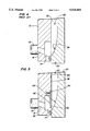
- FIG. 4 is a fragmentary cross-sectional view of a portion of a conventional continuous casting mold
- FIG. 5 is a fragmentary cross-sectional view of a portion of the mold that is depicted in FIGS. 1-3, corresponding to FIG. 4;
- FIG. 6 is a fragmentary cross-sectional view of another portion of the mold that is depicted in FIGS. 1-3 and 5.
- an improved continuous casting mold 10 that is constructed according to a preferred embodiment of the invention includes four outer walls 12 that each have a plenum 14 defined therein, as may be seen in FIG. 5.
- Each of the outer walls 12 further has a passage 16 defined therein, as may also be seen in FIG. 5, to communicate plenum 14 with a external conduit of coolant, which in the preferred embodiment is a water inlet supply pipe 18.
- Continuous casting mold 10 also includes four liner walls 20, each of which is secured to an inner surface 36, respectively, of an outer wall 12, as may best be seen in FIGS. 1 and 5.
- the liner walls 20 together define a mold surface through which molten material such as steel may be passed and shaped, as is well known in this area of technology.
- Each liner 20 or liner plate is preferably fabricated from a material that has high thermal connectivity, preferably copper, as is also well known in this technical area.
- each liner wall 20 has a number of slots 22 defined in an inner surface 24 thereof which, together with the respective outer wall 12, defines a number of passages 26, shown in FIG. 6, for transporting coolant such as water to cool the liner 20 during operation of the mold 10.
- each of the slots 22 has a radiused transition portion 28 that is proximate to a location where slot 22 communicates with the plenum 14. As is also depicted in FIG. 5, the transition portion 28 decreases in cross section as the slot 22 nears the plenum 14. The radius of the transition portion 28 is fairly large, for the reasons that are discussed above in the discussion of the problems that are associated with the prior art.
- FIG. 4 depicts a conventional mold, which also includes a plenum 14, a slot 22 and 1 radiused transition portion 28 that has a relatively large diameter. For the reasons discussed above, the water velocity in the plenum chamber and by the radius transition portion 28 is relatively low in comparison to that in a high velocity region 30 of the slot 22.
- one important aspect of the invention involves the provision of a velocity plate 32 that is positioned between the plenum 14 and the transition portion 28 of the slot 22.
- Velocity plate 32 functions to limit an opening through which coolant may flow between plenum 14 and transition portion 28, thereby increasing the velocity of coolant flow at this point. Because of the large radius of the transition portion 28, velocity plate 32 would create a significant impediment to water flow between the plenum 14 and the slot 22, if it were not for the provision of a number of tapered cutout portions 34 that are defined in a side of velocity plate 32 that faces the transition portion 28 of slot 22.
- FIGS. 2 and 3 it will be seen that a cutout portion 34 is provided on velocity plate 32 for each of the slots 22 that are defined in the liner plate 20. The cutout portions 34 are depicted in FIG. 3 in contrast to the flat portions 38.
- Velocity plate 32 is preferably secured to outer wall 12 by means of a bolt that presents substantially no resistance to coolant flow, such as the flat head bolt 40 that is depicted in FIG. 5.
- each of the cutout portions 34 in velocity plate 32 is substantially wider at the bottom of the velocity plate 32 than at the top of the velocity plate 32.
- This has the effect of maintaining a substantially uniform cross section, in a direction that is normal to the flow of coolant during operation, from the plenum 14 to the top of the region that is bounded by velocity plate 32 and transition portion 28, into the main portion of the slot 22.
- flow velocity remains relatively constant from the point the water leaves plenum 14 to the main portion of the slot 22.
- this will be within the range of substantially 20 feet per second to about 30 feet per second.
- the cooling rate along this portion liner 20 will be relatively even, minimizing stresses and prolonging the life of the liner 20.
- a velocity plate 32 is preferably mounted at both the top of the slot and at the bottom of the slot. However, it is most essential that a velocity plate be mounted at the top of the slot, because the minimization of mold face temperature gradients is most important at the top of the slot, which is close to the point of initial solidification or meniscus of the metal being casted.
- the invention also embraces a method of retrofitting a continuous casting mold of the type described above by separating the mold elements to expose the plenum and the transition portion, securing a velocity plate of the type described above between the plenum and the transition portion, and resealing the mold with the velocity plate mounted therein.
- This method can readily be envisioned by comparing FIG. 4 and 5.
Landscapes
- Engineering & Computer Science (AREA)
- Mechanical Engineering (AREA)
- Continuous Casting (AREA)
Abstract
Description
Claims (17)
Priority Applications (1)
| Application Number | Priority Date | Filing Date | Title |
|---|---|---|---|
| US08/314,746 US5526869A (en) | 1994-09-29 | 1994-09-29 | Mold for continuous casting system |
Applications Claiming Priority (1)
| Application Number | Priority Date | Filing Date | Title |
|---|---|---|---|
| US08/314,746 US5526869A (en) | 1994-09-29 | 1994-09-29 | Mold for continuous casting system |
Publications (1)
| Publication Number | Publication Date |
|---|---|
| US5526869A true US5526869A (en) | 1996-06-18 |
Family
ID=23221255
Family Applications (1)
| Application Number | Title | Priority Date | Filing Date |
|---|---|---|---|
| US08/314,746 Expired - Fee Related US5526869A (en) | 1994-09-29 | 1994-09-29 | Mold for continuous casting system |
Country Status (1)
| Country | Link |
|---|---|
| US (1) | US5526869A (en) |
Cited By (8)
| Publication number | Priority date | Publication date | Assignee | Title |
|---|---|---|---|---|
| WO2002022293A1 (en) * | 2000-09-11 | 2002-03-21 | Sms Demag, Inc. | System and process for optimizing cooling in continuous casting mold |
| US6367539B1 (en) * | 1999-01-13 | 2002-04-09 | Danieli & C. Officine Meccaniche Spa | Crystalliser for continuous casting |
| WO2003106073A3 (en) * | 2002-06-13 | 2004-04-08 | Sms Demag Ag | SHELL FOR CONTINUOUS CASTING OF LIQUID METALS, PARTICULARLY LIQUID STEEL |
| WO2004110677A1 (en) * | 1999-05-27 | 2004-12-23 | Ag Industries, Inc. | Liner for use in continuous casting mold |
| US6926067B1 (en) * | 1998-01-27 | 2005-08-09 | Km Europa Metal Ag | Liquid-cooled casting die |
| DE202014103977U1 (en) | 2013-09-03 | 2014-10-28 | Planeco Gmbh | stop device |
| CN107350437A (en) * | 2017-08-01 | 2017-11-17 | 尚成荣 | A kind of split type continuous cast mold of conductive copper material |
| CN109550909A (en) * | 2018-11-29 | 2019-04-02 | 何爱建 | The auxiliary heat conduction device of Ferrous Metallurgy continuous cast mold |
Citations (15)
| Publication number | Priority date | Publication date | Assignee | Title |
|---|---|---|---|---|
| US2169893A (en) * | 1937-11-01 | 1939-08-15 | Chase Brass & Copper Co | Cooling means for continuous casting apparatus |
| US2862265A (en) * | 1956-12-10 | 1958-12-02 | Aluminum Co Of America | Continuous casting mold |
| US2893080A (en) * | 1954-03-26 | 1959-07-07 | Norman P Goss | Apparatus for the continuous casting of metals |
| US3511305A (en) * | 1965-05-03 | 1970-05-12 | Alfred J Wertli | Method for cooling a continuous casting |
| US3528487A (en) * | 1967-06-05 | 1970-09-15 | Interlake Steel Corp | Continuous casting machine |
| US3763920A (en) * | 1972-03-16 | 1973-10-09 | United States Steel Corp | Water inlet construction for continuous-casting molds |
| US3978910A (en) * | 1975-07-07 | 1976-09-07 | Gladwin Floyd R | Mold plate cooling system |
| US4182397A (en) * | 1978-07-03 | 1980-01-08 | Allis-Chalmers Corporation | Continuous casting mold and means for securing mold liners therein |
| SU952422A1 (en) * | 1980-12-22 | 1982-08-23 | Могилевское Отделение Физико-Технического Института Ан Бсср | Continuous casting mould |
| US4535832A (en) * | 1981-04-29 | 1985-08-20 | Gus Sevastakis | Continuous casting apparatus |
| US4640337A (en) * | 1985-05-01 | 1987-02-03 | Gus Sevastakis | Continuous casting apparatus |
| JPH0342144A (en) * | 1989-07-06 | 1991-02-22 | Kawasaki Steel Corp | Method for cooling mold for continuous casting and mold thereof |
| US5117895A (en) * | 1987-12-23 | 1992-06-02 | Voest-Alpine Industrieanlagenbau Gesellschaft M.B.H. | Continuous casting mold arrangement |
| US5201909A (en) * | 1990-07-23 | 1993-04-13 | Mannesmann Aktiengesellschaft | Liquid-cooled continuous casting mold |
| US5207266A (en) * | 1992-01-03 | 1993-05-04 | Chuetsu Metal Works Co., Ltd. | Water-cooled copper casting mold |
-
1994
- 1994-09-29 US US08/314,746 patent/US5526869A/en not_active Expired - Fee Related
Patent Citations (15)
| Publication number | Priority date | Publication date | Assignee | Title |
|---|---|---|---|---|
| US2169893A (en) * | 1937-11-01 | 1939-08-15 | Chase Brass & Copper Co | Cooling means for continuous casting apparatus |
| US2893080A (en) * | 1954-03-26 | 1959-07-07 | Norman P Goss | Apparatus for the continuous casting of metals |
| US2862265A (en) * | 1956-12-10 | 1958-12-02 | Aluminum Co Of America | Continuous casting mold |
| US3511305A (en) * | 1965-05-03 | 1970-05-12 | Alfred J Wertli | Method for cooling a continuous casting |
| US3528487A (en) * | 1967-06-05 | 1970-09-15 | Interlake Steel Corp | Continuous casting machine |
| US3763920A (en) * | 1972-03-16 | 1973-10-09 | United States Steel Corp | Water inlet construction for continuous-casting molds |
| US3978910A (en) * | 1975-07-07 | 1976-09-07 | Gladwin Floyd R | Mold plate cooling system |
| US4182397A (en) * | 1978-07-03 | 1980-01-08 | Allis-Chalmers Corporation | Continuous casting mold and means for securing mold liners therein |
| SU952422A1 (en) * | 1980-12-22 | 1982-08-23 | Могилевское Отделение Физико-Технического Института Ан Бсср | Continuous casting mould |
| US4535832A (en) * | 1981-04-29 | 1985-08-20 | Gus Sevastakis | Continuous casting apparatus |
| US4640337A (en) * | 1985-05-01 | 1987-02-03 | Gus Sevastakis | Continuous casting apparatus |
| US5117895A (en) * | 1987-12-23 | 1992-06-02 | Voest-Alpine Industrieanlagenbau Gesellschaft M.B.H. | Continuous casting mold arrangement |
| JPH0342144A (en) * | 1989-07-06 | 1991-02-22 | Kawasaki Steel Corp | Method for cooling mold for continuous casting and mold thereof |
| US5201909A (en) * | 1990-07-23 | 1993-04-13 | Mannesmann Aktiengesellschaft | Liquid-cooled continuous casting mold |
| US5207266A (en) * | 1992-01-03 | 1993-05-04 | Chuetsu Metal Works Co., Ltd. | Water-cooled copper casting mold |
Cited By (14)
| Publication number | Priority date | Publication date | Assignee | Title |
|---|---|---|---|---|
| US6926067B1 (en) * | 1998-01-27 | 2005-08-09 | Km Europa Metal Ag | Liquid-cooled casting die |
| US6367539B1 (en) * | 1999-01-13 | 2002-04-09 | Danieli & C. Officine Meccaniche Spa | Crystalliser for continuous casting |
| WO2004110677A1 (en) * | 1999-05-27 | 2004-12-23 | Ag Industries, Inc. | Liner for use in continuous casting mold |
| RU2259256C2 (en) * | 2000-09-11 | 2005-08-27 | Смс Демаг, Инк. | Method of cooling mold for continuous casting of metal (versions) |
| US6374903B1 (en) * | 2000-09-11 | 2002-04-23 | Ag Industries, Inc. | System and process for optimizing cooling in continuous casting mold |
| WO2002022293A1 (en) * | 2000-09-11 | 2002-03-21 | Sms Demag, Inc. | System and process for optimizing cooling in continuous casting mold |
| WO2003106073A3 (en) * | 2002-06-13 | 2004-04-08 | Sms Demag Ag | SHELL FOR CONTINUOUS CASTING OF LIQUID METALS, PARTICULARLY LIQUID STEEL |
| US20060102313A1 (en) * | 2002-06-13 | 2006-05-18 | Gereon Fehlemann | Continuous casting mold for liquid metals, especially for liquid steel |
| US7363958B2 (en) | 2002-06-13 | 2008-04-29 | Sms Demag Ag | Continuous casting mold for liquid metals, especially for liquid steel |
| DE202014103977U1 (en) | 2013-09-03 | 2014-10-28 | Planeco Gmbh | stop device |
| CN107350437A (en) * | 2017-08-01 | 2017-11-17 | 尚成荣 | A kind of split type continuous cast mold of conductive copper material |
| CN107350437B (en) * | 2017-08-01 | 2019-05-17 | 南通卓尔机电有限公司 | A kind of split type continuous cast mold of conduction copper material |
| CN109550909A (en) * | 2018-11-29 | 2019-04-02 | 何爱建 | The auxiliary heat conduction device of Ferrous Metallurgy continuous cast mold |
| CN109550909B (en) * | 2018-11-29 | 2021-01-05 | 江苏永高钢丝制品有限公司 | Auxiliary heat conducting device of ferrous metallurgy continuous casting crystallizer |
Similar Documents
| Publication | Publication Date | Title |
|---|---|---|
| US5526869A (en) | Mold for continuous casting system | |
| US5221511A (en) | Strip casting | |
| EP0686445A1 (en) | Method to control the deformations of the sidewalls of a crystalliser, and continuous-casting crystalliser | |
| AU2001283736B2 (en) | Belt-cooling and guiding means for continuous belt casting of metal strip | |
| US5771958A (en) | Mold for continuous casting system | |
| CN102753285B (en) | For the supply mouth cast | |
| RO119995B1 (en) | DEVICE FOR THE VERTICAL POWER OF A METAL BAR | |
| TWI268821B (en) | Adjustment of heat transfer in continuous casting molds in particular in the region of the meniscus | |
| CN208033608U (en) | A kind of continuous cast mold | |
| CA2284190A1 (en) | Improved continuous casting mold and method | |
| EP1140392B1 (en) | High speed continuous casting device and relative method | |
| FI71245B (en) | METALL FORM | |
| EP1345720B1 (en) | Process for optimizing cooling in continuous casting mold | |
| CA1320335C (en) | Direct chill casting mould | |
| US20010017199A1 (en) | Continuous casting mold and processes for making and retrofitting | |
| JP2922252B2 (en) | Mold for continuous casting equipment | |
| US4139047A (en) | Inductor for electromagnetic casting | |
| JP3720376B2 (en) | Metal vertical hot top continuous casting mold | |
| JP2001526590A (en) | Casting wheel | |
| JP2002524262A (en) | Refractory nozzle | |
| WO1996035532A1 (en) | Mould | |
| CN220901827U (en) | Pulp pump body casting pouring system | |
| RU2030955C1 (en) | Metal continuous pouring crystallizer | |
| CN208945126U (en) | A kind of crystallizer of double water jacket structure | |
| EP0071401A1 (en) | A curved mold for continuous casting |
Legal Events
| Date | Code | Title | Description |
|---|---|---|---|
| AS | Assignment |
Owner name: PRIMACOR-GLADWIN CORP. (A CORP. OF DELAWARE), PEN Free format text: ASSIGNMENT OF ASSIGNORS INTEREST;ASSIGNOR:GLADWIN CORPORATION (A CORP. OF DELAWARE);REEL/FRAME:007235/0054 Effective date: 19941130 Owner name: GLADWIN CORPORATION, OHIO Free format text: ASSIGNMENT OF ASSIGNORS INTEREST;ASSIGNOR:SEARS, JAMES B. JR.;REEL/FRAME:007241/0386 Effective date: 19941123 |
|
| CC | Certificate of correction | ||
| AS | Assignment |
Owner name: AG INDUSTRIES, INC., PENNSYLVANIA Free format text: CHANGE OF NAME;ASSIGNOR:GLADWIN CORPORATION;REEL/FRAME:008423/0452 Effective date: 19960530 |
|
| FEPP | Fee payment procedure |
Free format text: PAYOR NUMBER ASSIGNED (ORIGINAL EVENT CODE: ASPN); ENTITY STATUS OF PATENT OWNER: SMALL ENTITY |
|
| FPAY | Fee payment |
Year of fee payment: 4 |
|
| AS | Assignment |
Owner name: SMS DEMAG, INC., PENNSYLVANIA Free format text: ASSIGNMENT OF ASSIGNORS INTEREST;ASSIGNOR:AG INDUSTRIES, INC.;REEL/FRAME:013467/0600 Effective date: 20020731 |
|
| LAPS | Lapse for failure to pay maintenance fees | ||
| FP | Lapsed due to failure to pay maintenance fee |
Effective date: 20040618 |
|
| STCH | Information on status: patent discontinuation |
Free format text: PATENT EXPIRED DUE TO NONPAYMENT OF MAINTENANCE FEES UNDER 37 CFR 1.362 |