US552443A - And joel c - Google Patents
And joel c Download PDFInfo
- Publication number
- US552443A US552443A US552443DA US552443A US 552443 A US552443 A US 552443A US 552443D A US552443D A US 552443DA US 552443 A US552443 A US 552443A
- Authority
- US
- United States
- Prior art keywords
- chamber
- buoyancy
- aeroplanes
- vessel
- aerial
- Prior art date
- Legal status (The legal status is an assumption and is not a legal conclusion. Google has not performed a legal analysis and makes no representation as to the accuracy of the status listed.)
- Expired - Lifetime
Links
- 238000010276 construction Methods 0.000 description 10
- 239000012530 fluid Substances 0.000 description 4
- QGZKDVFQNNGYKY-UHFFFAOYSA-N Ammonia Chemical compound N QGZKDVFQNNGYKY-UHFFFAOYSA-N 0.000 description 2
- RTZKZFJDLAIYFH-UHFFFAOYSA-N Diethyl ether Chemical compound CCOCC RTZKZFJDLAIYFH-UHFFFAOYSA-N 0.000 description 2
- UFHFLCQGNIYNRP-UHFFFAOYSA-N Hydrogen Chemical compound [H][H] UFHFLCQGNIYNRP-UHFFFAOYSA-N 0.000 description 2
- 229910052751 metal Inorganic materials 0.000 description 2
- 239000002184 metal Substances 0.000 description 2
- 238000005192 partition Methods 0.000 description 2
- VHUUQVKOLVNVRT-UHFFFAOYSA-N Ammonium hydroxide Chemical compound [NH4+].[OH-] VHUUQVKOLVNVRT-UHFFFAOYSA-N 0.000 description 1
- OYPRJOBELJOOCE-UHFFFAOYSA-N Calcium Chemical compound [Ca] OYPRJOBELJOOCE-UHFFFAOYSA-N 0.000 description 1
- OKTJSMMVPCPJKN-UHFFFAOYSA-N Carbon Chemical compound [C] OKTJSMMVPCPJKN-UHFFFAOYSA-N 0.000 description 1
- VEXZGXHMUGYJMC-UHFFFAOYSA-M Chloride anion Chemical compound [Cl-] VEXZGXHMUGYJMC-UHFFFAOYSA-M 0.000 description 1
- 230000002411 adverse Effects 0.000 description 1
- 229910052782 aluminium Inorganic materials 0.000 description 1
- XAGFODPZIPBFFR-UHFFFAOYSA-N aluminium Chemical compound [Al] XAGFODPZIPBFFR-UHFFFAOYSA-N 0.000 description 1
- 229910021529 ammonia Inorganic materials 0.000 description 1
- 235000011114 ammonium hydroxide Nutrition 0.000 description 1
- 230000001174 ascending effect Effects 0.000 description 1
- 239000011324 bead Substances 0.000 description 1
- 229910052791 calcium Inorganic materials 0.000 description 1
- 239000011575 calcium Substances 0.000 description 1
- 229910052799 carbon Inorganic materials 0.000 description 1
- 235000019506 cigar Nutrition 0.000 description 1
- 230000005611 electricity Effects 0.000 description 1
- 239000007789 gas Substances 0.000 description 1
- 238000004519 manufacturing process Methods 0.000 description 1
- 239000000463 material Substances 0.000 description 1
- 238000000034 method Methods 0.000 description 1
- 108010085990 projectin Proteins 0.000 description 1
- 230000001105 regulatory effect Effects 0.000 description 1
- 238000000638 solvent extraction Methods 0.000 description 1
- 239000000126 substance Substances 0.000 description 1
- 238000006467 substitution reaction Methods 0.000 description 1
- -1 vapor Chemical compound 0.000 description 1
Images
Classifications
-
- B—PERFORMING OPERATIONS; TRANSPORTING
- B64—AIRCRAFT; AVIATION; COSMONAUTICS
- B64B—LIGHTER-THAN AIR AIRCRAFT
- B64B1/00—Lighter-than-air aircraft
Definitions
- My invention relates to the construction of navigable aerial vessels designed to situpelled, maneuveied and steered by machinery arranged within the vesselitself, the latter having the necessary capacity for the carrying of passengers and freight and for making long voyages, the Whole structure being compact, strong, and adapted to overcome the chief obstacles heretofore encountered in aerial navigation-viz., head-winds and adverse currents and ordinary atmospheric resistance.
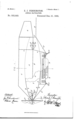
- Figure l is a View, mainly in longitudinal section, of my improved aerial vessel.
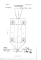
- Fig. 2 is a plan.
- Fig. is a transverse section on the line oc of Fig. l.
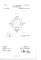
- Figs. 4 and 5 are enlarged details.
- the hull or buoyancy-chamber A of the vessel which generally is of cigar shape, is constructed with the view to lessening the
- the shell of the buoyancy-chamber isl made double, the inner and outer skins being represented by a and o, which are held apart, so that a space of uniform width is made between them, by means of bolts and thimbles, or other ,wellknown devices for the purpose, as shown on enlarged scale in Fig. 4.
- buoyancy-chamber A As undivided by partitions, or without sectional construction; but in other applications-wiz., Serial Nos. 427,952, 427,953, and 431,430-the interior construction ofthe buoyancy-chamber is shown, as also are the means of partitioning it or dividing it into sections, the methods of bracing, and other details. It is only necessary here to say that the construction of the buoyancychamber is such as to give it the greatest lpracticable preserved.
- the buoyancy-chamber A and most of its adj uncts or inferior parts are constructed of such material or metal as aluminum, which possesses the necessary strength, lightness, toughness and ductility for the purpose required, although I do not limit myself to its use, as other suitable metal or substance may be employed.
- the spaces between the two skins of the buoyancy-chamber are gas-tight, and by preference Iilled with hydrogen gas.
- Y B B represent what I term the aeroplanes, consisting of planes extending from the two outer sides of the buoyancy-chamber, prefer” ably at or near its axial line, although its position thereto is unessential.
- the iin C represents a vertical 1in ,running longitudinally of the upper part of the buoyancychamber in the axial line thereof.
- the iin C is connected by hollow braces c to the aeroplanes at the respective sides of the buoyancychamber.
- An under iin C is similarly ar- IOO ranged at the under side of the buoyancychamber, but divided into two longitudinal sections b v the car D.
- the earD occupies a length equal to about half that of the buoyancy-chamber A, and is suitably secured and braced thereto and also tothe aeroplanes; to the latter by means of the braces c c.
- the construction is such that the aeroplanes, upper and lower tins and the car are rigidly united and the aeroplanes and fins maintained in theirrespective horizontal and vertical planes.
- each of the aeroplanes B is mounted upon a vertical shaft d a side propeller E, driven by any suitable machinery.
- the aeroplanes B are provided with circular openings e, each .concentric with the shaft of the propeller adapted to revolve therein and in the plane of the aeroplane.
- the shaft of each ofthe side propellers E is provided with a bearing above and one below the aeroplanes B, which bearings are suitably braced to the latter.
- the objects of the side propellers D are to raise and lower'the vessel, as may be desired, in ascending and landing, and to assist, if necessary, the altitude-rudder in regulating the elevation when in ilight.
- the said propellers may be capable of either conjoint or independent action.
- Each end of the buoyancy-chamber A is closed by means of a bulkhead, that at the forward end being indicated by f and that at the aft end by f.
- Forward of the bulkhead f is a bearing f2, which, in connection with the bearing f3 at the prow of the buoyancy-chamber, supports the main propellershaft g, which is preferably hollow.
- the main propeller F Upon the shaft g is placed the main propeller F, the inner end of the shaft g being connected to a gas-engine or other motor, (herein shown generally by F.)
- the aft end of the hull or buoyancy-chamber is provided with a rudder G, standing in a vertical plane and hinged at its inner end to the buoyancy-chamber and the vertical iin C,the purpose of the rudder G being that ofthe ordinary rudder used in steering sea-vessels.
- the main propeller F the gen eral construction of which is specallyset forth and claimed in application Serial No. 427 ,956, is placed at the prow of the vessel and s0 constructed with respect to its blades f4 as to be capable, when in revolution, of producing a partial vacuum or of rarefying the atmosphere ahead of the vessel, so that propulsion is not effected, as is common in navigation by sea-vessels, by a thrust against the fluid upon which the propeller acts, but by the excess of pressure in the rear of the vessel due to the production of a partial vacuum or the rarefying of the air ahead.
- the blades of the propeller F are given a peculiar cha 1actcr or construction, adapting them to disturb or displace the atmosphere as it is encountered bythe prow of the buoyancy-chamber and to discharge it over the said chamber or hull, as more fully set forth in my application for Letters .Paten t, Serial No. 427,955.
- a chamber K Below and rigidly secured to the car D is a chamber K, divided longitudinally by preference into a central room 7L for storage-batteries to furnish electricity for any purpose and two lockers h for packages.
- a-s set forth more especially in my application Serial No. 440,7 70.
- This may be a naphtha, ammonia, vapor, aquaammonia, ether, chloride of calcium, or other engine.
- I do not here describe any motor or any means of using bisulphide of carbon or other medium as a motive-power fluid; but a motor adapted to the purpose in view is described in my application Serial No. 440,771, and means for supplying it with a motive fluid are set forth in application Serial No. 440, 770.
- Trucks L are provided below and rigidly secured to the car D for landing.
- I claim- 1 In an aerial vessel, a buoyancy chamber combined with a longitudinal fin projecting vertically from its back or upper portion', and aeroplanes projecting ina horizontal plane from the sides of said chamber, substantially as described.
- a buoyancy' chamber practically of cigar-shape, combined with a longitudinal fin projecting vertically from its back or upper portion, and aeroplanes projecting in a horizontal plane from the sides of said chamber, substantially as described.
- a buoyancy chamber combined with a longitudinal iin projecting vertically from its back or outer portion, aeroplanes projecting in a horizontal plane from the sides of said chamber, a car rigidly secured to the under side of the said buoyancy chamber, and fins extending longitudinally of the under side ofthe buoyancy chamber and uniting with the car, substantially as described.
- a buoyancy chamber having a longitudinal fin proj ectin g vertically from its back or upper portion, aeroplanes proj ecting in a horizontal plane from the sides of said chamber, a ear rigidly secured at the un.- der side of the buoyancy chamber, a iin proj ecting vertically from the under side of said buoyancy chamber and conneetin g with the IOO IIO
- a propeller at the forward'end or prow of the buoyancyA chamber a propeller at the forward'end or prow of the buoyancyA chamber, a rudder hinged in a vertical plane at the aft end of the buoyancy chamber, a rudder hinged in a horizontal plane also at said aft end of the buoyancy chamber', side propellers adapted to revolve in the plane of the aeroplanes, and suitable machinery for revolving the main propeller and the side propellers, and for steering, substantially as described.
- a buoyancy chamber practically of cigar-shape, combined with aeroplanes projecting in a horizontal plane from the sides thereof, propellers adapted to y revolve in the plane of said aeroplanes and suitable machinery for driving said side propellers, substantially as described.
- a buoyancy chamber having an upper and a loWer vertical n, and aeroplanes, combined With a shaft placed at the forward end of said buoyancy chamber axially thereof, a motor for driving said shaft, and a propeller mounted on said shaft, substantially as set forth.
- a buoyancy chamber having ⁇ an upper and a loWer vertical iin, and aeroplanes, combined With a shaft placed at the forward end of said buoyancy chamber axially thereof, a motor for driving said shaft, and a propeller mounted on said shaft, and having a diameter equal to, or exceeding that of, the greatest diameter of the buoyancy chamber, substantially as set forth.
Landscapes
- Engineering & Computer Science (AREA)
- Mechanical Engineering (AREA)
- Aviation & Aerospace Engineering (AREA)
- Other Liquid Machine Or Engine Such As Wave Power Use (AREA)
Description
(NoModel.) 3 Sheets-Sheet 1. E. J. PENNINGTON.
' AERIAL NAVIGATION. No. 552,443. Patented Deo. 3l, 1895.
C9 X E (No Model.) I 3 sheets-sheet 2. E. J. PENNINGTON.
' AERIAL NAVIGATION. No. 552,443. Patented Deo. 31, 1895.
4 fz/wifi?? I h A f (No Model.) 3 SheetsSheet 3. E. J. PENNINGTON.
AERIAL NAVIGATION Patented Dec. 3l, 1895.
FIG
A@ www resistance of the atmosphere.
UNTTED STATES PATENT muon.
EDIVARD J. IENNINGTON, OF MOUNT CARMEL, ILLINOIS, ASSIGNOR, BY DIRECT AND MESNE ASSIGNMENTS, TO VILLIAM B. KEEP, OF CHICAGO, ILLINOIS, AND JOEL C. PENNINGTON, OF MOORES HILL, INDIANA.
AERIAL NAVIGATION.
SPECIFICATION forming part of Letters Patent No. 552,443, dated December 31, 1895. Application filed April 5, 1892. Renewed December 11, 1895. Serial No. 571,737. (No model.)
To all whom t may concern:
Be it known that I, EDWARD J. PENNING- TON, of Mount Carmel, inthe county of Wabash and State of Illinois, have invented certain new and useful Improvements in Vessels for Aerial Navigation, of which the following is a specification, reference being had to the accompanying drawings and to theletters of reference marked thereon.
My invention relates to the construction of navigable aerial vessels designed to beimpelled, maneuveied and steered by machinery arranged within the vesselitself, the latter having the necessary capacity for the carrying of passengers and freight and for making long voyages, the Whole structure being compact, strong, and adapted to overcome the chief obstacles heretofore encountered in aerial navigation-viz., head-winds and adverse currents and ordinary atmospheric resistance.
In the accompanying drawings, Figure l is a View, mainly in longitudinal section, of my improved aerial vessel. Fig. 2 is a plan. Fig. is a transverse section on the line oc of Fig. l. Figs. 4 and 5 are enlarged details.
Similar letters of reference indicate similar parts in the respective figures.
The hull or buoyancy-chamber A of the vessel, which generally is of cigar shape, is constructed with the view to lessening the The shell of the buoyancy-chamber isl made double, the inner and outer skins being represented by a and o, which are held apart, so that a space of uniform width is made between them, by means of bolts and thimbles, or other ,wellknown devices for the purpose, as shown on enlarged scale in Fig. 4.
In my present application I show the buoyancy-chamber A as undivided by partitions, or without sectional construction; but in other applications-wiz., Serial Nos. 427,952, 427,953, and 431,430-the interior construction ofthe buoyancy-chamber is shown, as also are the means of partitioning it or dividing it into sections, the methods of bracing, and other details. It is only necessary here to say that the construction of the buoyancychamber is such as to give it the greatest lpracticable preserved.
possible resistance against the exterior pressure of air, or against collapse, by reason of the presence within it of a iiuid lighter than the atmosphere, and such as to permit the building of the buoyancy-chamber in sections for the purpose of convenience, ease of transportation and repair, and, if necessary, the substitution of new sections in the event that any first entering into the structure shall have become damaged or inoperative.
The buoyancy-chamber A and most of its adj uncts or inferior parts are constructed of such material or metal as aluminum, which possesses the necessary strength, lightness, toughness and ductility for the purpose required, although I do not limit myself to its use, as other suitable metal or substance may be employed. The spaces between the two skins of the buoyancy-chamber are gas-tight, and by preference Iilled with hydrogen gas.
Throughout the entire construction of my aerial vessel, wherever practicable, hollow bodies are charged with a fluid lighter than atmospheric air, whereby increased strength is obtained with the least possible weight, so that all parts of the vessel, including its bu oyancy-chamber, aeroplanes, car, fins, rudders, partitions, bracing, &C., and, so far as possible, its machinery, furniture and vappurtenances (as in my application, Serial No.'
427,957) are all made hollow and filled with a iiuid lighter than atmospheric air, preferably hydrogen gas,the buoyant qualities of the whole structure and outiit being as far as I also preferuto' bead or render tubular the edges of the aeroplanes, iins, rudders, and the like to give increased strength. This construction is shown on enlarged scale in Fig. 5 hereof.
Y B B represent what I term the aeroplanes, consisting of planes extending from the two outer sides of the buoyancy-chamber, prefer" ably at or near its axial line, although its position thereto is unessential. n
C represents a vertical 1in ,running longitudinally of the upper part of the buoyancychamber in the axial line thereof. The iin C is connected by hollow braces c to the aeroplanes at the respective sides of the buoyancychamber. An under iin C is similarly ar- IOO ranged at the under side of the buoyancychamber, but divided into two longitudinal sections b v the car D. The earD occupies a length equal to about half that of the buoyancy-chamber A, and is suitably secured and braced thereto and also tothe aeroplanes; to the latter by means of the braces c c. The construction is such that the aeroplanes, upper and lower tins and the car are rigidly united and the aeroplanes and fins maintained in theirrespective horizontal and vertical planes.
At each corner of each of the aeroplanes B is mounted upon a vertical shaft d a side propeller E, driven by any suitable machinery. (Not herein shown.) In order to provide for the reception of the propellers E the aeroplanes B are provided with circular openings e, each .concentric with the shaft of the propeller adapted to revolve therein and in the plane of the aeroplane. The shaft of each ofthe side propellers E is provided with a bearing above and one below the aeroplanes B, which bearings are suitably braced to the latter. The objects of the side propellers D are to raise and lower'the vessel, as may be desired, in ascending and landing, and to assist, if necessary, the altitude-rudder in regulating the elevation when in ilight. The said propellers may be capable of either conjoint or independent action.
Each end of the buoyancy-chamber A is closed by means of a bulkhead, that at the forward end being indicated by f and that at the aft end by f. Forward of the bulkhead f is a bearing f2, which, in connection with the bearing f3 at the prow of the buoyancy-chamber, supports the main propellershaft g, which is preferably hollow. Upon the shaft g is placed the main propeller F, the inner end of the shaft g being connected to a gas-engine or other motor, (herein shown generally by F.)
The propeller and shaft are claimed in my application Serial N o. 427,956.
The aft end of the hull or buoyancy-chamber is provided with a rudder G, standing in a vertical plane and hinged at its inner end to the buoyancy-chamber and the vertical iin C,the purpose of the rudder G being that ofthe ordinary rudder used in steering sea-vessels.
II is what I term the altitude-rudder, which normally rests in a horizontal plane, being hinged to the aft end of the buoyancychamber, as shown. In my present application I do not show mea-ns for vibrating either the rudder G (which I term the right or left7 rudder) or the al titude-rudder IVI; but the construction of and means for operating t'le rudders are claimed in my applications Serial Nos. 431,431, 429,666, and 429,667.
The main propeller F, the gen eral construction of which is specallyset forth and claimed in application Serial No. 427 ,956, is placed at the prow of the vessel and s0 constructed with respect to its blades f4 as to be capable, when in revolution, of producing a partial vacuum or of rarefying the atmosphere ahead of the vessel, so that propulsion is not effected, as is common in navigation by sea-vessels, by a thrust against the fluid upon which the propeller acts, but by the excess of pressure in the rear of the vessel due to the production of a partial vacuum or the rarefying of the air ahead. The blades of the propeller F are given a peculiar cha 1actcr or construction, adapting them to disturb or displace the atmosphere as it is encountered bythe prow of the buoyancy-chamber and to discharge it over the said chamber or hull, as more fully set forth in my application for Letters .Paten t, Serial No. 427,955.
Below and rigidly secured to the car D is a chamber K, divided longitudinally by preference into a central room 7L for storage-batteries to furnish electricity for any purpose and two lockers h for packages. rlhe space i' above the car D, between it and the buoyancy-chamber A, is employed as a reservoir for gas used for driving the gas-engine or principal motor, a-s set forth more especially in my application Serial No. 440,7 70. This may be a naphtha, ammonia, vapor, aquaammonia, ether, chloride of calcium, or other engine. I do not here describe any motor or any means of using bisulphide of carbon or other medium as a motive-power fluid; but a motor adapted to the purpose in view is described in my application Serial No. 440,771, and means for supplying it with a motive fluid are set forth in application Serial No. 440, 770.
Trucks L are provided below and rigidly secured to the car D for landing.
Having described my invention, I claim- 1. In an aerial vessel, a buoyancy chamber combined with a longitudinal fin projecting vertically from its back or upper portion', and aeroplanes projecting ina horizontal plane from the sides of said chamber, substantially as described. v
2. In an aerial vessel, a buoyancy' chamber, practically of cigar-shape, combined with a longitudinal fin projecting vertically from its back or upper portion, and aeroplanes projecting in a horizontal plane from the sides of said chamber, substantially as described.
3. In an aerial vessel, a buoyancy chamber combined with a longitudinal iin projecting vertically from its back or outer portion, aeroplanes projecting in a horizontal plane from the sides of said chamber, a car rigidly secured to the under side of the said buoyancy chamber, and fins extending longitudinally of the under side ofthe buoyancy chamber and uniting with the car, substantially as described.
4. In an aerial vessel, a buoyancy chamber having a longitudinal fin proj ectin g vertically from its back or upper portion, aeroplanes proj ecting in a horizontal plane from the sides of said chamber, a ear rigidly secured at the un.- der side of the buoyancy chamber, a iin proj ecting vertically from the under side of said buoyancy chamber and conneetin g with the IOO IIO
car, a propeller at the forward'end or prow of the buoyancyA chamber, a rudder hinged in a vertical plane at the aft end of the buoyancy chamber, a rudder hinged in a horizontal plane also at said aft end of the buoyancy chamber', side propellers adapted to revolve in the plane of the aeroplanes, and suitable machinery for revolving the main propeller and the side propellers, and for steering, substantially as described.
5. In an aerial vessel, a buoyancy chamber practically of cigar-shape, combined with aeroplanes projecting in a horizontal plane from the sides thereof, propellers adapted to y revolve in the plane of said aeroplanes and suitable machinery for driving said side propellers, substantially as described.
G. In an aerial vessel, a buoyancy chamber having an upper and a loWer vertical n, and aeroplanes, combined With a shaft placed at the forward end of said buoyancy chamber axially thereof, a motor for driving said shaft, and a propeller mounted on said shaft, substantially as set forth.
7. In an aerial vessel, a buoyancy chamber having` an upper and a loWer vertical iin, and aeroplanes, combined With a shaft placed at the forward end of said buoyancy chamber axially thereof, a motor for driving said shaft, and a propeller mounted on said shaft, and having a diameter equal to, or exceeding that of, the greatest diameter of the buoyancy chamber, substantially as set forth.
In testimony whereof I hereunto set my hand and seal.
y EDWARD J. PENN INGTON.
Witnesses R. H. BUTLER, W. G. ALLrsoN.
Publications (1)
| Publication Number | Publication Date |
|---|---|
| US552443A true US552443A (en) | 1895-12-31 |
Family
ID=2621184
Family Applications (1)
| Application Number | Title | Priority Date | Filing Date |
|---|---|---|---|
| US552443D Expired - Lifetime US552443A (en) | And joel c |
Country Status (1)
| Country | Link |
|---|---|
| US (1) | US552443A (en) |
Cited By (1)
| Publication number | Priority date | Publication date | Assignee | Title |
|---|---|---|---|---|
| US5026003A (en) * | 1989-08-28 | 1991-06-25 | Smith William R | Lighter-than-air aircraft |
-
0
- US US552443D patent/US552443A/en not_active Expired - Lifetime
Cited By (1)
| Publication number | Priority date | Publication date | Assignee | Title |
|---|---|---|---|---|
| US5026003A (en) * | 1989-08-28 | 1991-06-25 | Smith William R | Lighter-than-air aircraft |
Similar Documents
| Publication | Publication Date | Title |
|---|---|---|
| US3938759A (en) | Special aircraft using a novel integrated lift, propulsion and steering system | |
| US3450374A (en) | Resiliently flexible vehicle | |
| JP6426165B2 (en) | Hybrid VTOL machine | |
| US3559920A (en) | Crashproof light-weight vehicle | |
| US3753539A (en) | Ballooned, vtol aircraft | |
| US1422542A (en) | Multiple-hull boat | |
| US1686080A (en) | Cycloplane | |
| US1033186A (en) | Airship. | |
| US1002682A (en) | Telescopic airship. | |
| US970842A (en) | Aerial navigation. | |
| US2070854A (en) | Air vehicle | |
| US1734251A (en) | Aero propelling and steering means | |
| US1109502A (en) | Dirigible airship and the like. | |
| US678290A (en) | Propelling mechanism for vessels. | |
| US270939A (en) | Aerial ship | |
| US1738010A (en) | Flying machine | |
| US1289402A (en) | Airship. | |
| US311885A (en) | Vessel for aerial navigation | |
| US1088080A (en) | Driving mechanism for torpedoes. | |
| US259464A (en) | Vessel for aerial navigation | |
| US1513001A (en) | Airship of the semirigid type | |
| RU148428U1 (en) | COMBINED APPARATUS FOR USE IN WATER AND IN AIR | |
| US1077004A (en) | Airship. | |
| US1052204A (en) | Automatic balancing and horizontal sustaining aeroplane. | |
| US1684240A (en) | Aeronautics |