US5522657A - Optimization of electronic color printing process functions based on prescan information data - Google Patents
Optimization of electronic color printing process functions based on prescan information data Download PDFInfo
- Publication number
- US5522657A US5522657A US08/021,914 US2191493A US5522657A US 5522657 A US5522657 A US 5522657A US 2191493 A US2191493 A US 2191493A US 5522657 A US5522657 A US 5522657A
- Authority
- US
- United States
- Prior art keywords
- images
- image
- thermal energy
- array
- receiver sheet
- Prior art date
- Legal status (The legal status is an assumption and is not a legal conclusion. Google has not performed a legal analysis and makes no representation as to the accuracy of the status listed.)
- Expired - Fee Related
Links
Images


Classifications
-
- G—PHYSICS
- G03—PHOTOGRAPHY; CINEMATOGRAPHY; ANALOGOUS TECHNIQUES USING WAVES OTHER THAN OPTICAL WAVES; ELECTROGRAPHY; HOLOGRAPHY
- G03G—ELECTROGRAPHY; ELECTROPHOTOGRAPHY; MAGNETOGRAPHY
- G03G15/00—Apparatus for electrographic processes using a charge pattern
- G03G15/50—Machine control of apparatus for electrographic processes using a charge pattern, e.g. regulating differents parts of the machine, multimode copiers, microprocessor control
- G03G15/5025—Machine control of apparatus for electrographic processes using a charge pattern, e.g. regulating differents parts of the machine, multimode copiers, microprocessor control by measuring the original characteristics, e.g. contrast, density
-
- H—ELECTRICITY
- H04—ELECTRIC COMMUNICATION TECHNIQUE
- H04N—PICTORIAL COMMUNICATION, e.g. TELEVISION
- H04N1/00—Scanning, transmission or reproduction of documents or the like, e.g. facsimile transmission; Details thereof
- H04N1/23—Reproducing arrangements
- H04N1/2307—Circuits or arrangements for the control thereof, e.g. using a programmed control device, according to a measured quantity
- H04N1/233—Circuits or arrangements for the control thereof, e.g. using a programmed control device, according to a measured quantity according to characteristics of the data to be reproduced, e.g. number of lines
-
- H—ELECTRICITY
- H04—ELECTRIC COMMUNICATION TECHNIQUE
- H04N—PICTORIAL COMMUNICATION, e.g. TELEVISION
- H04N1/00—Scanning, transmission or reproduction of documents or the like, e.g. facsimile transmission; Details thereof
- H04N1/23—Reproducing arrangements
- H04N1/29—Reproducing arrangements involving production of an electrostatic intermediate picture
- H04N1/295—Circuits or arrangements for the control thereof, e.g. using a programmed control device, according to a measured quantity
-
- H—ELECTRICITY
- H04—ELECTRIC COMMUNICATION TECHNIQUE
- H04N—PICTORIAL COMMUNICATION, e.g. TELEVISION
- H04N1/00—Scanning, transmission or reproduction of documents or the like, e.g. facsimile transmission; Details thereof
- H04N1/32—Circuits or arrangements for control or supervision between transmitter and receiver or between image input and image output device, e.g. between a still-image camera and its memory or between a still-image camera and a printer device
- H04N1/32561—Circuits or arrangements for control or supervision between transmitter and receiver or between image input and image output device, e.g. between a still-image camera and its memory or between a still-image camera and a printer device using a programmed control device, e.g. a microprocessor
-
- H—ELECTRICITY
- H04—ELECTRIC COMMUNICATION TECHNIQUE
- H04N—PICTORIAL COMMUNICATION, e.g. TELEVISION
- H04N1/00—Scanning, transmission or reproduction of documents or the like, e.g. facsimile transmission; Details thereof
- H04N1/387—Composing, repositioning or otherwise geometrically modifying originals
-
- H—ELECTRICITY
- H04—ELECTRIC COMMUNICATION TECHNIQUE
- H04N—PICTORIAL COMMUNICATION, e.g. TELEVISION
- H04N1/00—Scanning, transmission or reproduction of documents or the like, e.g. facsimile transmission; Details thereof
- H04N1/46—Colour picture communication systems
-
- H—ELECTRICITY
- H04—ELECTRIC COMMUNICATION TECHNIQUE
- H04N—PICTORIAL COMMUNICATION, e.g. TELEVISION
- H04N1/00—Scanning, transmission or reproduction of documents or the like, e.g. facsimile transmission; Details thereof
- H04N1/46—Colour picture communication systems
- H04N1/56—Processing of colour picture signals
-
- G—PHYSICS
- G03—PHOTOGRAPHY; CINEMATOGRAPHY; ANALOGOUS TECHNIQUES USING WAVES OTHER THAN OPTICAL WAVES; ELECTROGRAPHY; HOLOGRAPHY
- G03G—ELECTROGRAPHY; ELECTROPHOTOGRAPHY; MAGNETOGRAPHY
- G03G2215/00—Apparatus for electrophotographic processes
- G03G2215/00172—Apparatus for electrophotographic processes relative to the original handling
- G03G2215/00206—Original medium
- G03G2215/00261—Plastic
- G03G2215/0027—Transparent film roll
-
- H—ELECTRICITY
- H04—ELECTRIC COMMUNICATION TECHNIQUE
- H04N—PICTORIAL COMMUNICATION, e.g. TELEVISION
- H04N2201/00—Indexing scheme relating to scanning, transmission or reproduction of documents or the like, and to details thereof
- H04N2201/0077—Types of the still picture apparatus
- H04N2201/0081—Image reader
-
- H—ELECTRICITY
- H04—ELECTRIC COMMUNICATION TECHNIQUE
- H04N—PICTORIAL COMMUNICATION, e.g. TELEVISION
- H04N2201/00—Indexing scheme relating to scanning, transmission or reproduction of documents or the like, and to details thereof
- H04N2201/0077—Types of the still picture apparatus
- H04N2201/0082—Image hardcopy reproducer
-
- H—ELECTRICITY
- H04—ELECTRIC COMMUNICATION TECHNIQUE
- H04N—PICTORIAL COMMUNICATION, e.g. TELEVISION
- H04N2201/00—Indexing scheme relating to scanning, transmission or reproduction of documents or the like, and to details thereof
- H04N2201/04—Scanning arrangements
- H04N2201/0402—Arrangements not specific to a particular one of the scanning methods covered by groups H04N1/04 - H04N1/207
- H04N2201/0404—Scanning transparent media, e.g. photographic film
- H04N2201/0408—Scanning film strips or rolls
-
- H—ELECTRICITY
- H04—ELECTRIC COMMUNICATION TECHNIQUE
- H04N—PICTORIAL COMMUNICATION, e.g. TELEVISION
- H04N2201/00—Indexing scheme relating to scanning, transmission or reproduction of documents or the like, and to details thereof
- H04N2201/04—Scanning arrangements
- H04N2201/0402—Arrangements not specific to a particular one of the scanning methods covered by groups H04N1/04 - H04N1/207
- H04N2201/0416—Performing a pre-scan
Definitions
- the present invention relates in general to electronic color printing of images contained in a filmstrip, and more particularly to optimization of process functions of electronic color printing based on information data, of images to be printed, obtained during a low resolution prescan of such images.
- Electronic printing, such as electrophotographic reproduction, by an apparatus for photofinishing of images contained in an original filmstrip has been shown and described in Jamzadeh et al U.S. Pat. No. 5,040,026, issued Aug. 13, 1991.
- Such apparatus operates to sequentially scan the respective image frames of an original filmstrip and produce, by an electrophotographic process, full color prints on a non-photosensitive print receiver sheet.
- a set of color separation marking particle images e.g., cyan, magenta, and yellow
- the set of color separation marking particle images are transferred in register to a print receiver sheet to form the desired full color print.
- each print receiver sheet is considerably larger than the commonly desired sizes of photographic prints.
- Several color prints are formed on each receiver sheet. For example, assuming a print receiver sheet having a size (in inches) of 12 ⁇ 18, it is disclosed in the aforementioned '026 patent that nine 4 ⁇ 6 prints be produced on the receiver sheet in a three-by-three, two dimensional array. This three-by-three array, referred to as a "9-up" format, would be a desirable format due to the current popularity of photographic prints of this 4 ⁇ 6 inch size.
- a print receiver sheet of this size in a two-by-two, or "four-up", format.
- the receiver sheet is then cut by any well known cutting and slitting apparatus to provide the smaller size prints or "snapshots".
- process functions for the electronic printing process are set in a manner to optimize the process.
- life of the photoconductive recording member may be maximized, marking particle consumption may be readily accommodated and substantially evenly accomplished, and thermal requirements may be accurately predicted and efficiently provided for.
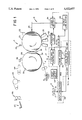
- FIG. 1 is a generally schematic illustration of an exemplary electronic printing apparatus for carrying out the generation of prints, in accordance with this invention
- FIGS. 3-5 illustrate various formats in which multicolor image frames can be printed by the electronic printing apparatus of FIG. 1;
- FIG. 6 is an illustration of an index print produced by the electronic printing apparatus of FIG. 1;
- FIG. 7 is a view, in cross-section and on an enlarged scale, of a typical photoconductive recording member
- FIG. 8 is a block diagram depicting information flow control for the exemplary electronic printing apparatus of FIG. 1;
- FIGS. 9a and 9b are schematic illustrations of respective image arrangements in the 9-up format.
- FIGS. 10a and 10b are respective histograms of marking particle stack heights for two images having the same overall marking particle usage but different scene contents.
- the filmstrip In order to utilize electronic printing for reproducing images from an array of multicolor images contained on a filmstrip, the filmstrip must be scanned by an electronic color scanner which conventionally includes for example a color-responsive CCD (such as shown in U.S. Pat. Nos. 4,638,371, or 4,639,769).
- the scanner operates to produce, line-by-line and pixel-by-pixel (a pixel is defined as a picture element), electronic signals representing the color content of each image contained in the scanned filmstrip.
- the signals are stored in a framestore (such as described in Jamzadeh et al U.S. Pat. No. 5,175,628, issued Dec. 29, 1992) to enable subsequent driving of an exposure device in the electronic printer.
- Electronically produced signals are also capable of being used for storage of an array of multicolor images (contained in an original filmstrip) on alternative storage media such as a still video floppy or a video disc.
- Image regeneration devices are then required to read out the stored signals from the alternative storage media for display for example on a CRT or a standard television set.
- Such single print receiver sheet bearing the complete array of filmstrip frame images is referred to as an "index print”.
- the production of prints, including the index print, for an array of image frames contained on a filmstrip (or video disk) or the like is accomplished by prescanning, at low resolution, an array of multicolor images contained on frames of a filmstrip.
- Information data, obtained during the low resolution prescan, of scene content of the respective image frames, and additional information data of at least one of where frames of the array are located in the filmstrip, what type of filmstrip is being scanned, the total number of frames on the filmstrip, and what are the conditions of each frame, are stored.
- FIG. 1 generally schematically illustrates an electrophotographic color printer capable of producing a plurality of multicolor image frames on a single print receiver sheet.
- the electrophotographic color printer designated generally by the letter P, is basically of the type set forth in the aforementioned U.S. Pat. No. 5,040,026, and is described below in sufficient detail for a complete understanding of this invention.
- the color printer could alternatively be, for example, a color ink jet printer, a color thermal printer, or any other suitable color electronic printer.
- the electrophotographic color printer P comprises a reusable image recording element, for example, a photoconductive recording member in the form of a drum 20.
- the drum 20 is rotated by a motor, not shown, in a clockwise direction (as viewed in FIG. 1) past a series of processing stations, all of which are well known in the art.
- These stations include a charging station 22 which operates to uniformly charge the photoconductive surface of the drum 20, and an exposure station 23.
- the exposure station 23 imagewise exposes the uniformly charged surface to create developable latent electrostatic images thereon.
- the exposure station may comprise a conventional LED printhead, an ion-depositing head, or as schematically shown, a laser writer 24.
- the intensity of the output beam of laser writer 24 is modulated with color-separated image information data, whereby a series of latent electrostatic images are produced on the drum surface, each representing a color-separated image of the ultimately desired multicolor print.
- the series of electrostatic images on drum 20 is rendered visible with different color marking particles (e.g., cyan, magenta and yellow toner), by development stations 25, 26 and 27 to produce a series of related toner images.
- These color-separated toner images are then transferred in registration to the print receiver sheet R carried on the periphery of a transfer drum 28.
- the photoconductive drum 20 is subsequently cleaned at a cleaning station 29 and recycled through the electrophotographic image-forming process.
- Print receiver sheets R are fed, seriatim, from a sheet supply 31 to an image-transfer station 32 defined by the nip between drum 20 and transfer drum 28. As each sheet approaches the image-transfer station 32, it is secured to the transfer drum 28 by vacuum means, gripping fingers or other suitable mechanisms. For example, the leading edge of the sheet can be secured to the transfer drum by vacuum through a row of vacuum ports 34 and the trailing end by vacuum through a row of vacuum ports 36.
- one color-separated toner image is transferred to a receiver sheet, for example, by heating the receiver sheet to a degree sufficient to soften the toner and tack the toner to the receiver sheet (see for example Light U.S. Pat. Nos. 4,968,578, issued Nov. 6, 1990; Ramai et al 4,927,727, issued May 22, 1990; and Johnson et al 5,021,835, issued Jun. 4, 1991).
- the transfer drum 28 After the transfer drum 28 has made three (four) revolutions and three related color-separated toner images (plus a black image if a fourth revolution is employed) have been transferred, in superimposed registration, to the surface of a print receiver sheet R, the leading edge of the receiver sheet is stripped from the transfer of drum 28 by stripping mechanism 38.
- the print receiver sheet R is transported by further rotation of the transfer drum 28 onto a sheet transport 44 which carries it to a fusing device 45 where the transferred images are fixed to the sheet by heat and/or pressure for example.
- the print receiver sheet R is then cut by any suitable cutting mechanism 46 to provide a plurality of smaller prints, each containing the reproduction from a single multicolor image frame.
- the resulting prints are collected in a tray 47 or more sophisticated print collecting device of any well known type.
- each print receiver sheet is of a relatively large size, for example, 12 inches by 18 inches.
- a print receiver sheet R can provide nine 4 ⁇ 6 inch print images (I 1 ', I 2 ', . . . I 9 ') exposed edge-to-edge with no waste.
- this format is commonly referred to as the "9-up" format.
- the other print sizes will produce some waste with a 12 ⁇ 18 inch print receiver sheet.
- FIG. 4 illustrates a "4-up" format in which four 5 ⁇ 7 inch print images (I 1 ", I 2 ", . . . I 4 ") are formed on a 12 ⁇ 18 inch print receiver sheet.
- a "2-up" format is shown in which two 8 ⁇ 10 inch print images (I 1 "', I 2 "') are formed on a 12 ⁇ 18 inch print receiver sheet.
- the input signals to exposure station 23 are provided by a conventional electronic color scanner S which includes a color-responsive CCD 51 (such as shown, for example, in aforementioned U.S. Pat. Nos. 4,638,371 and 4,639,769).
- Scanner S operates to scan an original multicolor image (e.g., as shown in FIG. 2, respective frames I 1 , I 2 , . . . I n of a 35 mm color negative filmstrip) as the filmstrip F is moved past the scanner by any well known drive mechanism (not shown).
- the scan is accomplished line-by-line and pixel-by-pixel, to produce three color-separated signals, R,G and B, representing the color content of each of the scanned image frames in three spectral regions, i.e., the red (R), green (G) and blue (B) spectral regions.
- R,G and B color-separated signals are produced substantially simultaneously and, as they are produced, they are fed to a framestore 60 (discussed below) via an input line buffer 58 of an image data manager 12.
- the latter serves to buffer a few lines of image data to account for any electronic protocol (SCSI communication) latencies at the scanner/framestore interface, and look-up-table needs inside the filmstrip scanner S.
- SCSI communication electronic protocol
- a logic and control unit (LCU) 61 operates through a data path controller 62 to control the flow of data into and out of the framestore 60, and manage the whereabouts of data in the framestore (i.e. provide a bookkeeping function).
- the LCU 61 also cooperates with a logic and control unit (LCU) 63 for the electrophotographic color printer P.
- the LCU 63 receives inputs from various portions of the electrophotographic color printer, including encoders (not shown) associated with the photoconductive and transfer drums (20 and 28, respectively), and transducers associated with the various processing stations to manage the timing of the entire printing process for such apparatus.
- One of the inputs to the LCU 61 is from a print format selector 64, whereby an operator can chose any of several different print sizes.
- the LCU 61 instructs the data path controller 62 to extract those pixels from the framestore 60 in the appropriate format required to produce the appropriate format image on a print receiver sheet R. For example, if 4 ⁇ 6 inch prints (i.e. "snapshots") are desired, the LCU 61 instructs the data path controller to extract the stored pixels in a format required to produce the 9-up format on the print receiver sheet. Similarly, if 5 ⁇ 7 inch prints are desired, the LCU 61 commands data path controller 62 to extract those pixels from memory in the required format to print images in the 4-up format.
- the framestore 60 is read out in a sequence required to produce multiple color-separated images on the photoconductive drum 20.
- the data read-out from the framestore 60 is applied to the laser writer 24 via an output line buffer 66 which serves to buffer a few lines of image information to account for latencies in the laser scanner/recording element interface, and data path image manipulation needs.
- the filmstrip F is first scanned by the scanner S at low resolution (referred to hereinafter as a prescan).
- the low resolution prescan of the scene content of an image frame on the filmstrip accomplished at on the order of 128 by 192 pixels, has been found sufficient to provide enough scene content data information to enable a recognizable print of an image from an array of image frames on a filmstrip.
- such low resolution prescan provides the necessary additional information data required for the LUT's needed for subsequent high resolution scanned printing of the filmstrip image frames.
- the total data storage for an array of filmstrip image frames is on the order of 20K bytes for each separation, well within the data storage capacity of commonly available, relatively inexpensive computer systems.
- the information data particularly related to at least the scene content of the images to be reproduced are analyzed in the data manager 12 by the LCU 61 to calculate various operating parameters to determine required process functions for the printer. Based on the determined required process functions, such functions are set to optimize the printing process. Particularly, the life of the photoconductive recording member may be maximized, marking particle consumption may be readily accommodated and substantially evenly accomplished, and thermal requirements may be accurately predicted and efficiently provided for.
- the recording member 20 In order to maximize the life of the photoconductive recording member (drum 20), stressing of the recording member must be reduced.
- the stress in the photoconductive recording member is induced by electrical fields utilized, as discussed above, in the formation of electrostatic latent images to be developed by the pigmented marking particles.
- the recording member 20 In a typical electrophotographic process, the recording member 20 generally consists of four primary layers (see FIG. 7). That is, the recording member, from bottom to top, consists of a support base 90, a grounding layer 92, a charge transport layer (CTL) 94, and a charge generation layer (CGL) 96. During the electrophotographic process, the recording member is first charged and then heavily discharged in the dark regions by heavy exposure.
- CTL charge transport layer
- the information data from the prescan can easily be processed by the logic and control unit 61 to produce photoconductive recording member exposure values for each color separation image of each image to be printed by the electronic printer P.
- the exposure values may be in terms of numbers indicating how dark or light the respective separation images will be overall. For example, darker separation images will result in larger numbers.
- Each number is calculated, for example, by averaging all the pixels of a respective separation image prescan information data, along with consideration for the spatial frequency contents of the separation image.
- the photoconductive recording member stress induced by each separation image can be predicted, the basic assumption being that the darker the image, the less the induced stress. While this is a good first order assumption, there are of course more sophisticated methods such as considering the spatial frequency of the separation image and the effective size of the beam used to expose the photoconductive recording member. From the stress history, subsequent exposures of the photoconductive recording member can be reordered to place highly stressful images in areas of the recording member which have been previously subjected to less stressful exposure and vice-a-versa. Specifically, in the described 9-up printing process, the history of the nine sections of the recording member can be ranked in the order of ascending stress.
- the predicted stress for the images that make up the next 9-up print can be ranked in the order of descending stress.
- the logic and control units 61 and 63 would then cooperate to cause the laser writer 24 to be driven so as to place the least stressful image in the area of the recording member which has previously been subjected to the most stress, the second least stressful image in the area of the recording member which has previously been subjected to the second most stress, and so on. Accordingly, the overall stress in the photoconductive recording member will be most closely balanced, and life shortening undue stresses will be avoided.
- the exposure is reversed by effectively rotating the image 180 degrees (read the image bottom-to-top instead of top-to-bottom, and right-to-left instead of left-to-right).
- images are read line-by-line from the frame store 60, interpolated, and sent to the laser writer 24 through the logic and control unit 63 for exposure of the photoconductive recording member 20 (see FIG. 8).
- Multiple line buffers facilitating data transfer, could be instructed to operate right-to-left or left-to-right. This will allow for pixel reversal.
- the image lines could be extracted backwards from the frame store.
- the frame store which is controlled by a microprocessor to keep track of the separation images exposed and to be exposed, could then be instructed to access the lines of a particular image in reverse order.
- the prescan information data is processed by the logic and control unit 61 as discussed above to yield numbers corresponding to the relative darkness of respective separation images to be developed.
- the respective concentration of marking particles in the development stations 25, 26, 27, is important to assure adequate image development for production of user acceptable prints. Heavy marking particle usage can prematurely reduce the concentration in a development station to an insufficient level where unacceptable image development occurs.
- determining the darkness of the images to be developed, the prescan information data, and using the darkness to predict the marking particle usage enables premature concentration reduction to be avoided. That is, once the marking particle usage has been predicted, the printer logic and control unit 63 can operate to accomplish replenishment of marking particles to the development stations at predetermined times to prevent concentration reaching an insufficient level.
- predicting marking particle usage more sophisticated than merely basing usage on image darkness can be used. For example, in an image, different pixels can be weighted differently in making the darkness calculation; or based on a scene balance algorithm, a subset of the pixels from the prescan information data may be used or given a different weight in the darkness calculation.
- the number of pixels and the spatial frequency of the pixels in the particular image are used. Spatial frequency refers to the transitions on adjacent pixels taken in both the in line and between line directions.
- the information data from the prescan can easily be processed to produce photoconductive recording member exposure values, in terms of numbers indicating how dark or light the respective separation images will be overall, by averaging all the pixels of a respective separation image prescan information data and considering the spatial frequency of hte separation image, and equating the darkness of an image with the usage (or take out) of marking particles to develop such image.
- FIGS. 9a and 9b respectively show two different possible arrangements of the same images in the 9-up printing format. Images with heavy marking particle usage are labelled with the letter "H”, images with medium marking particle usage are labelled with the letter “M”, and images with low marking particle usage are labelled with the letter "L”.
- the development station would experience substantially the same marking particle usage along its length (direction cross-track to direction of movement of the photoconductive recording member).
- the development station would experience a relatively high degree of marking particle usage adjacent one end (right end in FIG. 9b), along its length, and a relatively low degree of marking particle usage adjacent its opposite end (left end in FIG. 9b).
- the station may not have sufficient marking particles to adequately develop the "H" image in last row of 9-up images. Further, it is clear that the concentration of the marking particles in the development station would not be the same along the length of the station. In order to even out the marking particle concentration, there would have to be substantial mixing of the station contents, and this could result in rapid aging of the contents. Therefore, according to this invention, based on the information data obtained during the prescan, the images are exposed by the laser writer 23, under the control of the logic and control 63, so as to be repositioned in an order similar to the order shown in FIG. 9a.
- the prescan information data can also be used to predict marking particle stack heights so as to enable the transfer process efficiency to be optimized by repositioning the images as exposed on the photoconductive recording member to avoid bridging as discussed above.
- the simplest method for determining marking particle stack heights is to look at the darkness of the respective images. The basic good first order assumption is that the darker the image, the higher the average marking particle stack height.
- a more sophisticated method of predicting marking particle stack heights is to compute histograms of each separation image from the prescan information data.
- FIGS. 10a and 10b respectively show histograms of two images with substantially equal marking particle usage, but very different local marking particle stack heights. The image represented in the histogram shown in FIG.
- the object of this invention is accomplished by determining the marking particle stack heights (from the prescan information data), and positioning images having similar stack heights in the same row during printing so as to minimize the chances of poor transfer efficiency due to the bridging effect.
- Positioning (locating) the images based on their respective marking particle usage predictions is relatively easy when the images are monochrome.
- the images need only to be rank ordered, and then images with similar marking particle usage positioned next to each other.
- the images are multicolor, they respectively comprise three (or four) color separation images which must be summed to yield the total marking particle usage.
- the term 4! means four factorial or 4 ⁇ 3 ⁇ 2 ⁇ 1.
- the six possible combinations are listed in Table No. 2 with the differences on marking particle usage between each pair of images in each color separation.
- the differences are computed by subtracting the first image usage from the second image usage, i.e., b-a, c-a, d-a, . . . .
- This explains the reason for negative numbers in the above table.
- the pair (b,c) have the minimum difference in all 3 colors and therefore are the best matched images.
- the images of the next row will automatically be set as (a,d).
- the pair (a,d) does not seem to have similar toner usage in Cyan.
- the solution shown above for the 4-up example could be expanded to the 9 images of the 9-up print.
- the triplets would be (a,b,c), (a,b,d) (a,b,e), . . . (f,h,i), (g,h,i).
- the same rule as above is used to define the differences: c-b-a, d-b-a, . . . i-h-g.
- the probability of having triplets with identical marking particle usage is fairly low. There is an advantage to positioning the images with heavier take outs closer to the replenishment end of the development stations. The advantage is that the replenished marking particles need to travel less to compensate for the used (taken out) marking particles. This could prevent wide differences of marking particle concentration across the development stations and could help the process stability.
- the prescan information data is processed by the logic and control unit 61 as discussed above to yield numbers corresponding to the relative darkness of respective separation images to be developed. The darker the image, the heavier the usage (or take out) of marking particles to develop such image, and the greater the energy needs for the transfer and fusing processes.
- This information data from the image frames of a filmstrip, along with the number of frames on the filmstrip, can then be used to predict energy needs for making the prints thereof.
- the heaters for the transfer drum 28 and the fusing device 46 are controlled by temperature sensors (not shown) associated with the surfaces of the respective apparatus. When the surface temperatures drop below a lower limit, the respective heater elements are turned on. They stay on until the respective temperature sensor detects a temperature higher than a predetermined upper limit. The thicker (and heavier) the surface layer of the transfer drum or the fusing device, the longer it will take for the surface temperature rise or fall. The delay in achieving the desired temperature at the surface of the transfer drum, or the fusing device, makes precise control of the electronic printing process difficult. For example, when the surface temperature reaches the upper limit and the heater elements turn off, considerable amount of energy has already been radiated to the mass of the apparatus.
- This stored energy will cause the surface temperature to continue to rise for some finite time after the heating elements have been turned off. If the surface temperature of the transfer drum gets too high, the print receiver sheet will stick to the photoconductive recording member 20, and a very high surface temperature in the fusing device will result in the sticking of the print receiver sheet to the device. Both of these occurrences represent catastrophic failure conditions.
- the transfer drum 28 begins to transfer cold marking particles from the photoconductive recording member 20 to the print receiver sheet R (which is heated by the transfer drum), the surface temperature of the drum starts to drop.
- the heating elements will turn on but it will take some finite time for the energy to reach the drum surface.
- the transfer drum must continue to operate and heat the print receiver sheets as well as the marking particles. If the surface temperature of the transfer drum drops too low, the transfer efficiency will markedly decrease and the transferred images will have an unacceptable quality (will be motley in appearance).
- Low temperature in the fusing device results in low gloss of the images reproduced on the print receiver sheets, or ultimately, incomplete fusing of the images to the sheets. Again, this represents a condition which results in user unacceptable prints.
- E1c, E1m, and E1y respectively represent the thermal energies necessary in the transfer nip to sufficiently heat the print receiver sheet R and the marking particle stacks of cyan, magenta, and yellow separation images for efficient transfer of a particular print image.
- the values of E1c, E1m, and E1y are directly proportional to the height of the marking particle stacks. Such values are computed from the prescan information data indicating how dark the separation images are.
- Eg is the energy dissipated from the rest of the transfer drum (nip energy is excluded) during the normal operation; that Td represents the time delay for thermal energy to travel the thickness of the transfer drum 28; and that Tp represents the duration for transfer of a separation image.
- Td could be a few seconds to several minutes depending on the thickness and material comprising the transfer drum.
- the transfer drum heating elements would then be turned on Td before the print receiver sheet enters the transfer nip between the transfer drum 28 and the photoconductive recording member 20.
- the heating elements would be left on for Tp at a power level of (E1c+Eg)/Tp for transfer of the cyan separation image, (E1m+Eg)FFp for transfer of the magenta separation image, and (E1y+Eg)/Tp for transfer of the yellow separation image.
- the exact amount of thermal energy will be available in the transfer nip when it is called for.
- the heating elements will be powered down (to an idle power level) Td before the last print receiver sheet exits the transfer nip. This will prevent overheating of the transfer drum and will reduce the overall system energy consumption. It is of course clear that such process is equally applicable to controlling the thermal energy of the fusing device.
Landscapes
- Engineering & Computer Science (AREA)
- Multimedia (AREA)
- Signal Processing (AREA)
- Microelectronics & Electronic Packaging (AREA)
- Physics & Mathematics (AREA)
- General Physics & Mathematics (AREA)
- Computer Hardware Design (AREA)
- Accessory Devices And Overall Control Thereof (AREA)
Abstract
Description
              TABLE NO. 1
______________________________________
Cyan           Magenta  Yellow
______________________________________
a1             b2       d2
b7             c3       a3
c8             a8       c4
d9             d9       b4
______________________________________
              TABLE NO. 2
______________________________________
       a, b   a, c   a, d     b, c b, c   c, d
______________________________________
Cyan      6        7      8     1     2      1
Magenta  -6       -5     -1     1     7      6
Yellow    1        1     -1     0    -2     -2
______________________________________
Claims (39)
Priority Applications (1)
| Application Number | Priority Date | Filing Date | Title |
|---|---|---|---|
| US08/021,914 US5522657A (en) | 1993-02-24 | 1993-02-24 | Optimization of electronic color printing process functions based on prescan information data |
Applications Claiming Priority (1)
| Application Number | Priority Date | Filing Date | Title |
|---|---|---|---|
| US08/021,914 US5522657A (en) | 1993-02-24 | 1993-02-24 | Optimization of electronic color printing process functions based on prescan information data |
Publications (1)
| Publication Number | Publication Date |
|---|---|
| US5522657A true US5522657A (en) | 1996-06-04 |
Family
ID=21806816
Family Applications (1)
| Application Number | Title | Priority Date | Filing Date |
|---|---|---|---|
| US08/021,914 Expired - Fee Related US5522657A (en) | 1993-02-24 | 1993-02-24 | Optimization of electronic color printing process functions based on prescan information data |
Country Status (1)
| Country | Link |
|---|---|
| US (1) | US5522657A (en) |
Cited By (9)
| Publication number | Priority date | Publication date | Assignee | Title |
|---|---|---|---|---|
| EP0848542A2 (en) * | 1996-12-13 | 1998-06-17 | Fuji Photo Film Co., Ltd. | Image forming apparatus |
| EP0858211A2 (en) * | 1997-02-07 | 1998-08-12 | Canon Kabushiki Kaisha | Automatic control apparatus for color printer processing mode |
| US5850297A (en) * | 1995-03-27 | 1998-12-15 | Minolta Co., Ltd. | Image reading apparatus for reading first and second images |
| EP0936799A2 (en) * | 1998-02-09 | 1999-08-18 | Agfa-Gevaert Ag | Method and apparatus for digital capture of photographic films |
| US5946109A (en) * | 1996-06-21 | 1999-08-31 | Nikon Corporation | Picture image input method |
| US6067386A (en) * | 1997-09-26 | 2000-05-23 | Mustek Systems Inc. | Method and system for automatic image-property identification for an optical scanner |
| US6348940B1 (en) * | 1996-10-31 | 2002-02-19 | Minolta Co., Ltd. | Image forming apparatus and system and a recording medium |
| EP1533992A2 (en) * | 1996-11-20 | 2005-05-25 | Fuji Photo Film Co., Ltd | Picture image outputting method and photograph finishing system using the method |
| US20060084005A1 (en) * | 2004-10-19 | 2006-04-20 | Eastman Kodak Company | Means to enable slitting of micro-encapsulated media |
Citations (16)
| Publication number | Priority date | Publication date | Assignee | Title |
|---|---|---|---|---|
| US4638371A (en) * | 1985-03-11 | 1987-01-20 | Eastman Kodak Company | Multiple exposure of area image sensor having a sparse array of elements |
| US4639769A (en) * | 1985-04-01 | 1987-01-27 | Eastman Kodak Company | Modifying color digital images |
| US4927727A (en) * | 1988-08-09 | 1990-05-22 | Eastman Kodak Company | Thermally assisted transfer of small electrostatographic toner particles |
| US4968578A (en) * | 1988-08-09 | 1990-11-06 | Eastman Kodak Company | Method of non-electrostatically transferring toner |
| US5021835A (en) * | 1990-06-04 | 1991-06-04 | Eastman Kodak Company | Multicolor imaging apparatus with improved transfer means |
| US5040026A (en) * | 1990-03-05 | 1991-08-13 | Eastman Kodak Company | Method and apparatus for transferring color toner images in registration |
| US5049985A (en) * | 1988-10-13 | 1991-09-17 | Canon Kabushiki Kaisha | Color images reading apparatus having transformation table formed base on average values of plural color component signals |
| US5062058A (en) * | 1988-03-17 | 1991-10-29 | Fuji Photo Film Co., Ltd. | Image processing method for color scanner |
| US5079624A (en) * | 1988-09-02 | 1992-01-07 | Fuji Xerox Co., Ltd. | Digital image processing apparatus |
| US5164837A (en) * | 1990-10-04 | 1992-11-17 | Dainippon Screen Mfg. Co., Ltd. | Method of correcting setup parameter decision characteristics and automatic setup apparatus using a neural network |
| US5173783A (en) * | 1990-11-27 | 1992-12-22 | Dainippon Screen Mfg. Co., Ltd. | Method of recording images on photosensitive material in a process scanner device using setup data stored in a portable memory after generating the setup data by statistical analysis of image signals in a separate setup scanner device |
| US5175628A (en) * | 1991-09-30 | 1992-12-29 | Eastman Kodak Company | Memory management for electronic color printer |
| US5194946A (en) * | 1988-10-13 | 1993-03-16 | Fuji Photo Film Co., Ltd. | Color scanner and automatic setting method of signal processing conditions |
| US5210600A (en) * | 1990-01-08 | 1993-05-11 | Fuji Xerox Co., Ltd. | Extraction of film image parameters in image processing apparatus |
| US5223954A (en) * | 1989-09-08 | 1993-06-29 | Fuji Photo Film Co., Ltd. | System for producing a halftone film or a printing plate |
| US5369426A (en) * | 1993-03-31 | 1994-11-29 | Eastman Kodak Company | Method and apparatus for optimization of productivity through the synchronization of a scanner and printer using a pre-scan |
-
1993
- 1993-02-24 US US08/021,914 patent/US5522657A/en not_active Expired - Fee Related
Patent Citations (16)
| Publication number | Priority date | Publication date | Assignee | Title |
|---|---|---|---|---|
| US4638371A (en) * | 1985-03-11 | 1987-01-20 | Eastman Kodak Company | Multiple exposure of area image sensor having a sparse array of elements |
| US4639769A (en) * | 1985-04-01 | 1987-01-27 | Eastman Kodak Company | Modifying color digital images |
| US5062058A (en) * | 1988-03-17 | 1991-10-29 | Fuji Photo Film Co., Ltd. | Image processing method for color scanner |
| US4927727A (en) * | 1988-08-09 | 1990-05-22 | Eastman Kodak Company | Thermally assisted transfer of small electrostatographic toner particles |
| US4968578A (en) * | 1988-08-09 | 1990-11-06 | Eastman Kodak Company | Method of non-electrostatically transferring toner |
| US5079624A (en) * | 1988-09-02 | 1992-01-07 | Fuji Xerox Co., Ltd. | Digital image processing apparatus |
| US5194946A (en) * | 1988-10-13 | 1993-03-16 | Fuji Photo Film Co., Ltd. | Color scanner and automatic setting method of signal processing conditions |
| US5049985A (en) * | 1988-10-13 | 1991-09-17 | Canon Kabushiki Kaisha | Color images reading apparatus having transformation table formed base on average values of plural color component signals |
| US5223954A (en) * | 1989-09-08 | 1993-06-29 | Fuji Photo Film Co., Ltd. | System for producing a halftone film or a printing plate |
| US5210600A (en) * | 1990-01-08 | 1993-05-11 | Fuji Xerox Co., Ltd. | Extraction of film image parameters in image processing apparatus |
| US5040026A (en) * | 1990-03-05 | 1991-08-13 | Eastman Kodak Company | Method and apparatus for transferring color toner images in registration |
| US5021835A (en) * | 1990-06-04 | 1991-06-04 | Eastman Kodak Company | Multicolor imaging apparatus with improved transfer means |
| US5164837A (en) * | 1990-10-04 | 1992-11-17 | Dainippon Screen Mfg. Co., Ltd. | Method of correcting setup parameter decision characteristics and automatic setup apparatus using a neural network |
| US5173783A (en) * | 1990-11-27 | 1992-12-22 | Dainippon Screen Mfg. Co., Ltd. | Method of recording images on photosensitive material in a process scanner device using setup data stored in a portable memory after generating the setup data by statistical analysis of image signals in a separate setup scanner device |
| US5175628A (en) * | 1991-09-30 | 1992-12-29 | Eastman Kodak Company | Memory management for electronic color printer |
| US5369426A (en) * | 1993-03-31 | 1994-11-29 | Eastman Kodak Company | Method and apparatus for optimization of productivity through the synchronization of a scanner and printer using a pre-scan |
Cited By (16)
| Publication number | Priority date | Publication date | Assignee | Title |
|---|---|---|---|---|
| US5850297A (en) * | 1995-03-27 | 1998-12-15 | Minolta Co., Ltd. | Image reading apparatus for reading first and second images |
| US5946109A (en) * | 1996-06-21 | 1999-08-31 | Nikon Corporation | Picture image input method |
| US6348940B1 (en) * | 1996-10-31 | 2002-02-19 | Minolta Co., Ltd. | Image forming apparatus and system and a recording medium |
| EP1533992A2 (en) * | 1996-11-20 | 2005-05-25 | Fuji Photo Film Co., Ltd | Picture image outputting method and photograph finishing system using the method |
| EP1533992A3 (en) * | 1996-11-20 | 2005-08-17 | Fuji Photo Film Co., Ltd | Picture image outputting method and photograph finishing system using the method |
| EP0848542A3 (en) * | 1996-12-13 | 2000-01-19 | Fuji Photo Film Co., Ltd. | Image forming apparatus |
| US6342957B1 (en) | 1996-12-13 | 2002-01-29 | Fuji Photo Film Co., Ltd. | Image forming apparatus |
| EP0848542A2 (en) * | 1996-12-13 | 1998-06-17 | Fuji Photo Film Co., Ltd. | Image forming apparatus |
| CN100399789C (en) * | 1996-12-13 | 2008-07-02 | 富士胶片株式会社 | Image forming device |
| EP0858211A3 (en) * | 1997-02-07 | 1999-11-17 | Canon Kabushiki Kaisha | Automatic control apparatus for color printer processing mode |
| US6120197A (en) * | 1997-02-07 | 2000-09-19 | Canon Kabushiki Kaisha | Printer color processing mode automatic control apparatus, method, receiving apparatus, system, and its storing medium |
| EP0858211A2 (en) * | 1997-02-07 | 1998-08-12 | Canon Kabushiki Kaisha | Automatic control apparatus for color printer processing mode |
| US6067386A (en) * | 1997-09-26 | 2000-05-23 | Mustek Systems Inc. | Method and system for automatic image-property identification for an optical scanner |
| EP0936799A2 (en) * | 1998-02-09 | 1999-08-18 | Agfa-Gevaert Ag | Method and apparatus for digital capture of photographic films |
| EP0936799A3 (en) * | 1998-02-09 | 2000-10-18 | Agfa-Gevaert Ag | Method and apparatus for digital capture of photographic films |
| US20060084005A1 (en) * | 2004-10-19 | 2006-04-20 | Eastman Kodak Company | Means to enable slitting of micro-encapsulated media |
Similar Documents
| Publication | Publication Date | Title |
|---|---|---|
| JP5111222B2 (en) | Image processing apparatus and image processing method | |
| CN101105656B (en) | Image forming apparatus | |
| US5504583A (en) | Generation of prints from an array of images and information relative to such images | |
| EP1005219B1 (en) | Image output processing apparatus | |
| US20060066925A1 (en) | Image forming apparatus, image processor, image processing method, and storage medium storing program | |
| EP0794653B1 (en) | Image-forming apparatus | |
| US20060087709A1 (en) | Image processing apparatus and method | |
| US5522657A (en) | Optimization of electronic color printing process functions based on prescan information data | |
| US7301677B2 (en) | Image forming system, image distribution apparatus, and image forming method | |
| EP0893909B1 (en) | Image forming device | |
| US5760928A (en) | Image forming apparatus utilizing plural image forming methods and recording agent color detection | |
| EP0448104A2 (en) | Multi-color image forming apparatus | |
| US6204932B1 (en) | Image forming apparatus | |
| JPS61111071A (en) | Color-image forming device | |
| US6269185B1 (en) | Image processing apparatus and image forming apparatus | |
| US5748345A (en) | Image processing apparatus for performing image processing according to colors of input image | |
| EP0535345B1 (en) | Memory management for electronic color printer | |
| US5765074A (en) | Transfer device and image forming apparatus using said transfer device | |
| JP2000019906A (en) | Image forming device | |
| US20040109176A1 (en) | Printing system and distributed image forming method | |
| JPH1188687A (en) | Device and method for processing image | |
| EP0508123A1 (en) | Image processing apparatus | |
| US7324235B2 (en) | Imaging apparatus capable of efficient management of page memory | |
| JPH11125987A (en) | Image forming device | |
| EP1289272B1 (en) | Plane dependent compression |
Legal Events
| Date | Code | Title | Description |
|---|---|---|---|
| AS | Assignment |
Owner name: EASTMAN KODAK COMPANY, NEW YORK Free format text: ASSIGNMENT OF ASSIGNORS INTEREST.;ASSIGNORS:JAMZADEH, FERAYDOON SHAHJAHAN;ZEMAN, ROBERT EDWARD;REEL/FRAME:006463/0688 Effective date: 19930224 |
|
| FEPP | Fee payment procedure |
Free format text: PAYOR NUMBER ASSIGNED (ORIGINAL EVENT CODE: ASPN); ENTITY STATUS OF PATENT OWNER: LARGE ENTITY |
|
| FEPP | Fee payment procedure |
Free format text: PAYER NUMBER DE-ASSIGNED (ORIGINAL EVENT CODE: RMPN); ENTITY STATUS OF PATENT OWNER: LARGE ENTITY Free format text: PAYOR NUMBER ASSIGNED (ORIGINAL EVENT CODE: ASPN); ENTITY STATUS OF PATENT OWNER: LARGE ENTITY |
|
| FPAY | Fee payment |
Year of fee payment: 4 |
|
| FPAY | Fee payment |
Year of fee payment: 8 |
|
| REMI | Maintenance fee reminder mailed | ||
| LAPS | Lapse for failure to pay maintenance fees | ||
| LAPS | Lapse for failure to pay maintenance fees |
Free format text: PATENT EXPIRED FOR FAILURE TO PAY MAINTENANCE FEES (ORIGINAL EVENT CODE: EXP.); ENTITY STATUS OF PATENT OWNER: LARGE ENTITY |
|
| STCH | Information on status: patent discontinuation |
Free format text: PATENT EXPIRED DUE TO NONPAYMENT OF MAINTENANCE FEES UNDER 37 CFR 1.362 |
|
| FP | Lapsed due to failure to pay maintenance fee |
Effective date: 20080604 |