US5520514A - Sealing lining between vanes and intermediate platforms - Google Patents
Sealing lining between vanes and intermediate platforms Download PDFInfo
- Publication number
- US5520514A US5520514A US08/391,028 US39102895A US5520514A US 5520514 A US5520514 A US 5520514A US 39102895 A US39102895 A US 39102895A US 5520514 A US5520514 A US 5520514A
- Authority
- US
- United States
- Prior art keywords
- rotor
- vanes
- platforms
- casing
- assembly
- Prior art date
- Legal status (The legal status is an assumption and is not a legal conclusion. Google has not performed a legal analysis and makes no representation as to the accuracy of the status listed.)
- Expired - Fee Related
Links
Images


Classifications
-
- F—MECHANICAL ENGINEERING; LIGHTING; HEATING; WEAPONS; BLASTING
- F01—MACHINES OR ENGINES IN GENERAL; ENGINE PLANTS IN GENERAL; STEAM ENGINES
- F01D—NON-POSITIVE DISPLACEMENT MACHINES OR ENGINES, e.g. STEAM TURBINES
- F01D11/00—Preventing or minimising internal leakage of working-fluid, e.g. between stages
- F01D11/005—Sealing means between non relatively rotating elements
- F01D11/006—Sealing the gap between rotor blades or blades and rotor
- F01D11/008—Sealing the gap between rotor blades or blades and rotor by spacer elements between the blades, e.g. independent interblade platforms
Definitions
- the invention concerns a sealing lining disposed in an assembly of vanes on a blowing disk and intermediate platforms, thus forming a rotor.
- the invention therefore is applicable to productions where the platforms are embodied as detached elements of the vanes and each extend between one pair of vanes, thus forming a play (i.e. clearance) with each of them, which unfortunately implies that the plays are significant along the vanes owing to the complex shape of said vanes and particularly as regards their curve and the need to dismantle the platforms.
- the platforms are kept in position between the vanes by two ferrules, one being situated upstream of the rotor and the other downstream.
- the invention may also be applicable to a rotor whose platforms possess a foot housed in alveoles machined in the disk.
- the invention concerns a sealing lining able to be placed in each of these plays and which fills them up correctly.
- it concerns an assembly for a rotor composed of vanes embedded in the rotor and platforms situated between consecutive pairs of vanes, mainly longitudinal plays existing between the vanes and the platforms, this assembly being characterized in that it includes sealing linings occupying the plays and formed of a casing composed of a face bearing against the flanks of the platforms and one flexible face directed towards the surfaces of the vanes.
- the casing may be composed of a face bearing against the surfaces of the vanes and a flexible face directed towards the flanks of the platforms.
- the linings are again formed of a solid "long line" (i.e. elongated) element in the casing which may be sectorized or composed of a plurality of elements.
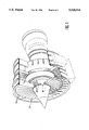
- FIG. 1 is a general view of a machine where the invention is used
- FIG. 2 is a cross section of the assembly representing a platform kept in place by upstream and downstream ferrules
- FIG. 3 is a section in the circumferential direction of the assembly of FIG. 2,
- FIG. 4 is a partially exploded top view
- FIG. 5 is a detailed view of FIG. 3 and which illustrates the behaviour of the sealing lining when the engine rotates in accordance with the invention
- FIG. 6 is a section in the circumferential direction of one variant of the invention.
- FIG. 7 is a view similar to FIG. 5 and which shows a further embodiment of the invention.
- FIG. 1 mainly shows a turbojet engine provided, as in the normal case, with several stages of compressors, turbines, etc., and which opens as shown on the left of the figure by an inlet blower S composed of a rotor disk 8 bearing a circular stage of radial vanes 1 which separate platforms 2 delimiting a flow vein.
- FIG. 3 shows two adjacent vanes 1 and an intermediate platform 2 composed of a central spar 3 and cores 4 on both sides of the spar 3.
- the cores 4 have external flanks orientated towards the vanes 1 and which bulge outwardly in a radial direction.
- the play (i.e. clearance) 7 with the vanes 1, determined by the mounting method, is merely a few millimeters.
- the platform elements 2 are made of a composite material, which significantly lightens the rotor.
- FIG. 2 shows them extending over the entire length of the disk 8 and projecting on two sides by an upstream lengthening piece 10 and a downstream lengthening piece 11.
- An upstream ferrule 12 and a downstream ferrule 13 joined side by side to the lateral faces of the disk 8 and fixed to these faces according to known dispositions respectively cover the lengthening pieces 10 and 11 of the platform elements 2 and thus retain these elements against the axial and radial movements.
- the platform elements 2 are supported by the ferrules 12 and 13 at several tenths of a millimeter from the surface of the disk 8.
- the sealing linings which occupy the plays (i.e. clearances) 7 bear the general reference 15 on FIG. 3.
- Each is composed of a casing 16 formed of one internal face 17, one external face 18 and a radially internal heel 19.
- the section of the casing 16 is thus triangular as represented at the time the platform elements 2 are inserted.
- a rod-shaped "long line" (i.e. elongated) element 20 is engaged in the casing 16 and occupies one portion of the volume it includes.
- the rod 20 is not strictly flexible and may be made of a metal or composite material, yet its weight is sufficient to enable it to move in the casing 16 under the action of the centrifugal forces created during operation.
- the casing 16 is made of elastomer, its outer face 18 and the heel 19 are able to warp, and the rod 20 is free to slide inside the casing 16 towards the outside so as to draw close to the play 7 and fill it.
- the rod 20 is preferably cylindrical as regards all its sections so as to facilitate its sliding.
- the casing 16 then assumes the shape of a triangle whose point is directed in a radial direction towards the inside instead of being directed outwardly,
- the internal face 17 remains glued to the corresponding flank 6.
- FIG. 4 shows a centripetal view of this embodiment of the invention.
- Each platform element 2 bears two similar sealing linings 15, even if the respective plays 7a and 7b, which separate the edge of the platform element 2 from the vanes 1 between which it is situated, may be different: the flexibility of the casing 16 makes it possible to fill the wide, though narrow, plays 7. It ought to be mentioned that the flanks 6 of the platform elements 2 are approximately parallel to the flanks of the vanes 1 and extend in front of the latter and that the sealing linings 15 are curved in a similar way. The plays 7 are thus filled over their entire length by an approximately uniform translation movement of the rods 20.
- FIG. 6 shows an embodiment in which the platform elements 2, like the vanes 1, have a foot 5 engaged in an alveole of the disk 8 effected by a broaching.
- the ferrules 12 and 13 may then be omitted.
- FIG. 7 shows a further embodiment of the invention in which the internal face, here 17', of the casing 16' of the sealing linings 15 is glued to the flank of the vane 1, and the outer face 18' and the heel 19' are directed towards the flank 6 of the platform 2. Functioning here is the same, as the centrifugal forces move the rod 20 towards the narrow portion of the play and thus fill it.
Landscapes
- Engineering & Computer Science (AREA)
- Mechanical Engineering (AREA)
- General Engineering & Computer Science (AREA)
- Turbine Rotor Nozzle Sealing (AREA)
- Structures Of Non-Positive Displacement Pumps (AREA)
Abstract
Description
Claims (4)
Applications Claiming Priority (2)
| Application Number | Priority Date | Filing Date | Title |
|---|---|---|---|
| FR9402025 | 1994-02-23 | ||
| FR9402025A FR2716502B1 (en) | 1994-02-23 | 1994-02-23 | Sealing between vanes and intermediate platforms. |
Publications (1)
| Publication Number | Publication Date |
|---|---|
| US5520514A true US5520514A (en) | 1996-05-28 |
Family
ID=9460331
Family Applications (1)
| Application Number | Title | Priority Date | Filing Date |
|---|---|---|---|
| US08/391,028 Expired - Fee Related US5520514A (en) | 1994-02-23 | 1995-02-21 | Sealing lining between vanes and intermediate platforms |
Country Status (4)
| Country | Link |
|---|---|
| US (1) | US5520514A (en) |
| EP (1) | EP0669451B1 (en) |
| DE (1) | DE69501973T2 (en) |
| FR (1) | FR2716502B1 (en) |
Cited By (12)
| Publication number | Priority date | Publication date | Assignee | Title |
|---|---|---|---|---|
| US5700133A (en) * | 1995-09-21 | 1997-12-23 | Societe Nationale D'etude Et De Construction De Moteurs D'aviation Snecma | Damper disposition mounted between rotor vanes |
| DE19654471A1 (en) * | 1996-12-27 | 1998-07-02 | Asea Brown Boveri | Arrangement for fixing rotor or stator blades in turbine |
| JP2003522872A (en) * | 2000-02-09 | 2003-07-29 | シーメンス アクチエンゲゼルシヤフト | Turbine blade arrangement structure |
| US20040219014A1 (en) * | 2003-04-29 | 2004-11-04 | Remy Synnott | Diametrically energized piston ring |
| CN100430606C (en) * | 2004-01-05 | 2008-11-05 | 财团法人工业技术研究院 | High-speed cantilever centrifugal compressor rotor mechanism |
| US20090269203A1 (en) * | 2008-04-07 | 2009-10-29 | Rolls-Royce Plc | Aeroengine fan assembly |
| US20100021302A1 (en) * | 2006-11-23 | 2010-01-28 | Siemens Aktiengesellschaft | Blade Arrangement |
| US7762781B1 (en) | 2007-03-06 | 2010-07-27 | Florida Turbine Technologies, Inc. | Composite blade and platform assembly |
| US8827651B2 (en) | 2010-11-01 | 2014-09-09 | Rolls-Royce Plc | Annulus filler |
| US20160032734A1 (en) * | 2013-03-15 | 2016-02-04 | Snecma | Fan for a multi-flow turboshaft engine, and turboshaft engine equipped with such a fan |
| US9926798B2 (en) | 2014-08-13 | 2018-03-27 | Rolls-Royce Corporation | Method for manufacturing composite fan annulus filler having nano-coating |
| CN115076147A (en) * | 2021-03-16 | 2022-09-20 | 中国航发商用航空发动机有限责任公司 | Aircraft engine fan and aircraft engine |
Families Citing this family (1)
| Publication number | Priority date | Publication date | Assignee | Title |
|---|---|---|---|---|
| GB9602129D0 (en) * | 1996-02-02 | 1996-04-03 | Rolls Royce Plc | Rotors for gas turbine engines |
Citations (12)
| Publication number | Priority date | Publication date | Assignee | Title |
|---|---|---|---|---|
| GB1331209A (en) * | 1969-10-28 | 1973-09-26 | Secr Defence | Bladed rotors for fluid flow machines |
| US4111603A (en) * | 1976-05-17 | 1978-09-05 | Westinghouse Electric Corp. | Ceramic rotor blade assembly for a gas turbine engine |
| EP0081416A1 (en) * | 1981-12-03 | 1983-06-15 | Societe Nationale D'etude Et De Construction De Moteurs D'aviation, "S.N.E.C.M.A." | Damping device for the blades of a turbo machine fan |
| US4784573A (en) * | 1987-08-17 | 1988-11-15 | United Technologies Corporation | Turbine blade attachment |
| FR2619158A1 (en) * | 1987-08-05 | 1989-02-10 | Gen Electric | DEVICE FOR SEALING AND DAMPING THE VIBRATIONS OF THE PLATFORM OF A TURBINE BLADE |
| EP0488874A1 (en) * | 1990-11-28 | 1992-06-03 | Societe Nationale D'etude Et De Construction De Moteurs D'aviation "Snecma" | Fan rotor with blades without platforms and fillers reconstructing the streamline profile |
| US5156528A (en) * | 1991-04-19 | 1992-10-20 | General Electric Company | Vibration damping of gas turbine engine buckets |
| US5222865A (en) * | 1991-03-04 | 1993-06-29 | General Electric Company | Platform assembly for attaching rotor blades to a rotor disk |
| WO1993022539A1 (en) * | 1992-05-07 | 1993-11-11 | Rolls-Royce Plc | Rotors for gas turbine engines |
| US5277548A (en) * | 1991-12-31 | 1994-01-11 | United Technologies Corporation | Non-integral rotor blade platform |
| US5415526A (en) * | 1993-11-19 | 1995-05-16 | Mercadante; Anthony J. | Coolable rotor assembly |
| US5421704A (en) * | 1993-06-10 | 1995-06-06 | Societe Nationale D'etude Et De Construction De Moteurs D'aviation "Snecma" | Inter-blade platform for a bladed disc of a turbomachine rotor |
-
1994
- 1994-02-23 FR FR9402025A patent/FR2716502B1/en not_active Expired - Fee Related
-
1995
- 1995-02-21 EP EP95400353A patent/EP0669451B1/en not_active Expired - Lifetime
- 1995-02-21 DE DE69501973T patent/DE69501973T2/en not_active Expired - Fee Related
- 1995-02-21 US US08/391,028 patent/US5520514A/en not_active Expired - Fee Related
Patent Citations (12)
| Publication number | Priority date | Publication date | Assignee | Title |
|---|---|---|---|---|
| GB1331209A (en) * | 1969-10-28 | 1973-09-26 | Secr Defence | Bladed rotors for fluid flow machines |
| US4111603A (en) * | 1976-05-17 | 1978-09-05 | Westinghouse Electric Corp. | Ceramic rotor blade assembly for a gas turbine engine |
| EP0081416A1 (en) * | 1981-12-03 | 1983-06-15 | Societe Nationale D'etude Et De Construction De Moteurs D'aviation, "S.N.E.C.M.A." | Damping device for the blades of a turbo machine fan |
| FR2619158A1 (en) * | 1987-08-05 | 1989-02-10 | Gen Electric | DEVICE FOR SEALING AND DAMPING THE VIBRATIONS OF THE PLATFORM OF A TURBINE BLADE |
| US4784573A (en) * | 1987-08-17 | 1988-11-15 | United Technologies Corporation | Turbine blade attachment |
| EP0488874A1 (en) * | 1990-11-28 | 1992-06-03 | Societe Nationale D'etude Et De Construction De Moteurs D'aviation "Snecma" | Fan rotor with blades without platforms and fillers reconstructing the streamline profile |
| US5222865A (en) * | 1991-03-04 | 1993-06-29 | General Electric Company | Platform assembly for attaching rotor blades to a rotor disk |
| US5156528A (en) * | 1991-04-19 | 1992-10-20 | General Electric Company | Vibration damping of gas turbine engine buckets |
| US5277548A (en) * | 1991-12-31 | 1994-01-11 | United Technologies Corporation | Non-integral rotor blade platform |
| WO1993022539A1 (en) * | 1992-05-07 | 1993-11-11 | Rolls-Royce Plc | Rotors for gas turbine engines |
| US5421704A (en) * | 1993-06-10 | 1995-06-06 | Societe Nationale D'etude Et De Construction De Moteurs D'aviation "Snecma" | Inter-blade platform for a bladed disc of a turbomachine rotor |
| US5415526A (en) * | 1993-11-19 | 1995-05-16 | Mercadante; Anthony J. | Coolable rotor assembly |
Cited By (18)
| Publication number | Priority date | Publication date | Assignee | Title |
|---|---|---|---|---|
| US5700133A (en) * | 1995-09-21 | 1997-12-23 | Societe Nationale D'etude Et De Construction De Moteurs D'aviation Snecma | Damper disposition mounted between rotor vanes |
| DE19654471A1 (en) * | 1996-12-27 | 1998-07-02 | Asea Brown Boveri | Arrangement for fixing rotor or stator blades in turbine |
| US5961286A (en) * | 1996-12-27 | 1999-10-05 | Asea Brown Boveri Ag | Arrangement which consists of a number of fixing slots and is intended for fitting a rotor or a stator of a fluid-flow machine with blades |
| DE19654471B4 (en) * | 1996-12-27 | 2006-05-24 | Alstom | Rotor of a turbomachine |
| JP2003522872A (en) * | 2000-02-09 | 2003-07-29 | シーメンス アクチエンゲゼルシヤフト | Turbine blade arrangement structure |
| US20040219014A1 (en) * | 2003-04-29 | 2004-11-04 | Remy Synnott | Diametrically energized piston ring |
| US6916154B2 (en) | 2003-04-29 | 2005-07-12 | Pratt & Whitney Canada Corp. | Diametrically energized piston ring |
| CN100430606C (en) * | 2004-01-05 | 2008-11-05 | 财团法人工业技术研究院 | High-speed cantilever centrifugal compressor rotor mechanism |
| US8167563B2 (en) * | 2006-11-23 | 2012-05-01 | Siemens Aktiengesellschaft | Blade arrangement |
| US20100021302A1 (en) * | 2006-11-23 | 2010-01-28 | Siemens Aktiengesellschaft | Blade Arrangement |
| US7762781B1 (en) | 2007-03-06 | 2010-07-27 | Florida Turbine Technologies, Inc. | Composite blade and platform assembly |
| US20090269203A1 (en) * | 2008-04-07 | 2009-10-29 | Rolls-Royce Plc | Aeroengine fan assembly |
| EP2108786A3 (en) * | 2008-04-07 | 2012-12-26 | Rolls-Royce plc | Aeroengine fan assembly |
| US8535013B2 (en) | 2008-04-07 | 2013-09-17 | Rolls-Royce Plc | Aeroengine fan assembly |
| US8827651B2 (en) | 2010-11-01 | 2014-09-09 | Rolls-Royce Plc | Annulus filler |
| US20160032734A1 (en) * | 2013-03-15 | 2016-02-04 | Snecma | Fan for a multi-flow turboshaft engine, and turboshaft engine equipped with such a fan |
| US9926798B2 (en) | 2014-08-13 | 2018-03-27 | Rolls-Royce Corporation | Method for manufacturing composite fan annulus filler having nano-coating |
| CN115076147A (en) * | 2021-03-16 | 2022-09-20 | 中国航发商用航空发动机有限责任公司 | Aircraft engine fan and aircraft engine |
Also Published As
| Publication number | Publication date |
|---|---|
| FR2716502A1 (en) | 1995-08-25 |
| DE69501973T2 (en) | 1998-08-20 |
| DE69501973D1 (en) | 1998-05-14 |
| FR2716502B1 (en) | 1996-04-05 |
| EP0669451A1 (en) | 1995-08-30 |
| EP0669451B1 (en) | 1998-04-08 |
Similar Documents
| Publication | Publication Date | Title |
|---|---|---|
| US5520514A (en) | Sealing lining between vanes and intermediate platforms | |
| RU2451215C2 (en) | Rotary assembly of gas turbine fan, gas turbine engine, fan with said assembly and gas turbine engine | |
| US5636968A (en) | Device for assembling a circular stage of pivoting vanes | |
| EP0654586B1 (en) | Stator vane assembly | |
| EP0844369B1 (en) | A bladed rotor and surround assembly | |
| EP2395200B1 (en) | Gas turbine engine blade mounting arrangement | |
| RU2673361C1 (en) | Device for guiding adjustable stator blades of turbine engine and method of assembling said device | |
| US5242270A (en) | Platform motion restraints for freestanding turbine blades | |
| CA1253439A (en) | Turbomachinery blade mounting arrangement | |
| CA2406479C (en) | Weep plug | |
| RU2693671C2 (en) | Angular sector of stator with gas turbine engine blades with axial compressor (versions) and gas turbine engine with axial compressor, which contains such angular sector | |
| CN105026123A (en) | Monobloc preformed unit and blade for turbo machine | |
| CA2478623C (en) | Machine stator and assembly and disassembly methods | |
| WO2015130381A2 (en) | A gas turbine engine integrally bladed rotor with asymmetrical trench fillets | |
| JP5890601B2 (en) | Rotor assembly of turbomachine and its assembly method | |
| WO2014168743A1 (en) | Integrally bladed rotor | |
| JP2006529014A (en) | Spoke centering brush seal structure used in gas turbines | |
| JP2004028094A (en) | Turbine bucket cover and method of assembling the same | |
| CA2185854C (en) | Damper disposition mounted between rotor vanes | |
| US20070081899A1 (en) | Apparatus and method for attaching a rotor blade to a rotor | |
| RU2269678C1 (en) | Axial-flow compressor for gas-turbine engine | |
| RU2157925C2 (en) | Guide vanes of axial-flow compressor | |
| US3019736A (en) | Centrifugal pumping means | |
| JP7269029B2 (en) | Blades and rotating machinery | |
| RU2109172C1 (en) | Centrifugal compressor |
Legal Events
| Date | Code | Title | Description |
|---|---|---|---|
| AS | Assignment |
Owner name: SOCIETE NATIONALE D'ETUDE ET DE CONSTRUCTION DE MO Free format text: ASSIGNMENT OF ASSIGNORS INTEREST;ASSIGNORS:MAREIX, JEAN-PIERRE LOUIS;PABION, PHILIPE JEAN-PIERRE;REEL/FRAME:007425/0601 Effective date: 19950131 |
|
| AS | Assignment |
Owner name: SOCIETE NATIONALE D'ETUDE ET DE CONSTRUCTION DE MO Free format text: CORRECTIV;ASSIGNORS:MAREIX, JEAN-PIERRE L.;PABION, PHILIPPE JEAN-PIERRE;REEL/FRAME:007515/0256 Effective date: 19950131 |
|
| REMI | Maintenance fee reminder mailed | ||
| LAPS | Lapse for failure to pay maintenance fees | ||
| FP | Lapsed due to failure to pay maintenance fee |
Effective date: 20000528 |
|
| STCH | Information on status: patent discontinuation |
Free format text: PATENT EXPIRED DUE TO NONPAYMENT OF MAINTENANCE FEES UNDER 37 CFR 1.362 |