US5519513A - Techniques for illuminating objects - Google Patents
Techniques for illuminating objects Download PDFInfo
- Publication number
- US5519513A US5519513A US08/486,489 US48648995A US5519513A US 5519513 A US5519513 A US 5519513A US 48648995 A US48648995 A US 48648995A US 5519513 A US5519513 A US 5519513A
- Authority
- US
- United States
- Prior art keywords
- illumination
- cavity
- imaging
- lambertian
- objects
- Prior art date
- Legal status (The legal status is an assumption and is not a legal conclusion. Google has not performed a legal analysis and makes no representation as to the accuracy of the status listed.)
- Expired - Fee Related
Links
Images


Classifications
-
- G—PHYSICS
- G02—OPTICS
- G02B—OPTICAL ELEMENTS, SYSTEMS OR APPARATUS
- G02B27/00—Optical systems or apparatus not provided for by any of the groups G02B1/00 - G02B26/00, G02B30/00
- G02B27/09—Beam shaping, e.g. changing the cross-sectional area, not otherwise provided for
- G02B27/0938—Using specific optical elements
- G02B27/0977—Reflective elements
- G02B27/0983—Reflective elements being curved
-
- H—ELECTRICITY
- H04—ELECTRIC COMMUNICATION TECHNIQUE
- H04N—PICTORIAL COMMUNICATION, e.g. TELEVISION
- H04N1/00—Scanning, transmission or reproduction of documents or the like, e.g. facsimile transmission; Details thereof
- H04N1/024—Details of scanning heads ; Means for illuminating the original
- H04N1/028—Details of scanning heads ; Means for illuminating the original for picture information pick-up
- H04N1/02815—Means for illuminating the original, not specific to a particular type of pick-up head
- H04N1/0282—Using a single or a few point light sources, e.g. a laser diode
- H04N1/02835—Using a single or a few point light sources, e.g. a laser diode in combination with a light guide, e.g. optical fibre, glass plate
-
- H—ELECTRICITY
- H04—ELECTRIC COMMUNICATION TECHNIQUE
- H04N—PICTORIAL COMMUNICATION, e.g. TELEVISION
- H04N1/00—Scanning, transmission or reproduction of documents or the like, e.g. facsimile transmission; Details thereof
- H04N1/024—Details of scanning heads ; Means for illuminating the original
- H04N1/028—Details of scanning heads ; Means for illuminating the original for picture information pick-up
- H04N1/02815—Means for illuminating the original, not specific to a particular type of pick-up head
- H04N1/0282—Using a single or a few point light sources, e.g. a laser diode
- H04N1/0284—Using a single or a few point light sources, e.g. a laser diode in combination with a light integrating, concentrating or diffusing cavity
-
- G—PHYSICS
- G02—OPTICS
- G02B—OPTICAL ELEMENTS, SYSTEMS OR APPARATUS
- G02B27/00—Optical systems or apparatus not provided for by any of the groups G02B1/00 - G02B26/00, G02B30/00
- G02B27/48—Laser speckle optics
Definitions
- This invention relates to arrangements for illuminating objects, and particularly to such involving an integrating cylinder and associated illumination-coupling means.
- This invention provides an illumination system that can be useful with an electronic image-capture system, giving a combined platform apt for integration in a high-speed processor.
- This platform provides the ability capture a video image of an object as it passes through the processor at full speed, and direct the captured image data to additional electronics which process and compress the captured data.
- the data may then be stored in storage and retrieval systems where it may be accessed for further manipulation and processing, displayed on video workstations, printed (typically using high-definition laser printers), transmitted electronically from point to point, placed in an archive system where it may be stored for long periods, or any combination of these processes as defined by the system parameters.
- Such processes, or combinations of processes are typically controlled by mainframe computers which act as "host" systems to link multiple imaging systems, storage and retrieval systems and other peripherals.
- the transport systems for which this imaging platform is contemplated are capable of transporting objects past processing stations at speeds between 100 to 400 inches per second (ips, or 2.54 to 10.16 meters per second mps).
- the objects with a typical thickness of 0.005 inches (0.125 millimeters) move along a vertical constraining channel known as a "track, " having a width of typically 0.070 to 0.090 inches (1.78 to 2.29 millimeters), known as the "track gap".
- This "track gap” is made considerably wider than the width of the object to accommodate variations due to tolerances and also to accommodate foreign objects (e.g. documents with staples, paper-clips and the like) which inevitably are attached to such objects from time to time.
- the field of view to be captured by an imaging system such as the one described here is largely defined by the maximum height of the objects (e.g. documents) which must be captured.
- the objects here contemplated are typically between 2.75 to 4.75 inches (70.0 to 121.0 millimeters) high and between 6.0 and 10.0 inches (152.0 and 254.0 millimeters) long.
- Image capture is achieved by passing the object in front of a photosensitive device known as a CCPD, well known to workers in the art. This consists of a large number of very small, individual photosensitive receptors, disposed in a linear array. The object is passed in front of the CCPD as a natural function of the object transport, and a complete image of the object linear segments individually captured from the CCPD, a process known in the art as "line scanning".
- a CCPD photosensitive device
- line scanning a process known in the art as "line scanning”.
- the photoreceptors of the CCPD consist of a semiconductor material which is formulated to convert incident light into an analogue electrical signal, which varies in potential depending upon the intensity incident light.
- the captured image thus consists of many individual records from each receptor, known as "pixels", each having a particular analogue potential which corresponds to the intensity of the incident light during the time the individual record was captured.
- the time available for a receptor to capture this data is very short.
- the document transport velocity is 300 ips (7.62 mps) and the preferred perceived size of an individual pixel is 0.005" (0.125 millimeters) square.
- the time available for the individual receptor to capture the data related to particular pixel is 0.005 ⁇ 300 or approximately 17 millionths of a second (17 microseconds). At the maximum velocity (of which the preferred embodiment is capable.), this time may be as brief as 12.5 microseconds.
- This time is known to workers in the art as "integration time", since it describes the time available for the photosensitive receptor to gather all the photons which have struck its surface and integrate their energy to produce an analog potential (i.e. electronic image).
- the CCPD of choice in the preferred embodiment is the Reticon RL1288D, a linear array device contained in the familiar "chip"-style package, which contains sufficient receptors to allow us to image said documents at the preferred pixel size and can maintain the necessary data rates (up to 80 megabytes per second) to permit imaging at the preferred document speeds.
- This device is commercially available and attractively priced.
- the illumination system must provide enough light to produce adequate signal from the CCPD under the worst possible conditions for document, transport, CCPD, optics and processing electronics.
- the illumination system should also provide lighting which is uniform over the entire surface of the document to be imaged, in order that the CCPD may provide a consistent response for a given condition at different points on the document.
- the illumination must also be correctly devised to accurately render the colour and contrast of the document, since the CCPD is a monochrome device which will render images only in shades of grey.
- An object hereof is to teach a means of deriving such illumination.
- the image should not contain data which is not visible to the human eye; this might tend to confuse or obscure the imaged data which is human-visible.
- the illumination must also be spectrally correct, taking into consideration the spectral response of the CCPD (which does not necessarily mimic that of the human eye) and the effects of any optical elements used in the image camera.
- This combined response must approximate the response of the human eye, known to workers in the art as "photopic response.” Failure to match this response may result in startling artifacts in the captured image, such as images of inks or imprints which are not visible to the human eye but are perceived by the CCPD as a result of its own spectral response, or the spectral characteristics of the illumination, or both.
- Such artifacts are particularly common with the increasing use of security-motivated imprints and watermarks which are invisible to the unaided eye but which will fluoresce in the visible spectrum when illuminated at extra-photopic frequencies, such as ultra-violet light.
- CCPD Complementary Metal-Oxide-Oxide-Oxide-Oxide-S-Oxide-S-Oxide-S-Oxide-S-Oxide-S-Oxide-S-Oxide-S-Oxide-S-Oxide-S-Oxide-S-Oxide-S-Oxide-S-Oxide-S-Oxide-S-Oxide-S-Ox-opticalber
- the optical system for capturing the image from the document thus becomes somewhat more complex, and is generally referred to as a "camera”.
- IMAGER IMAGER
- two such illumination/camera units are required, and we prefer to further combine both units into a single IMAGER module, which contains complete illumination systems and imaging optics/CCPDs for both front and rear faces of the document (e.g. see IMAGER embodiment of FIGS. 2-6).
- An important goal is to make the parts of the two illumination systems and cameras identical so far as possible.
- Imaging camera system of the type described Data captured from an imaging camera system of the type described is increasingly useful for tasks beyond the simple matters of document viewing and archiving.
- Various electronic systems are now being employed to read printed and handwritten data on financial instruments such as checks, with advantages for speedy, automated handling of such documents, as will be well understood by workers in the art. If such systems are to be employed, it is highly desirable that imaging cameras of the type described produce data in a consistent format which will not vary substantially from camera to camera.
- recognition systems rely heavily on tables and databases of previous "experience" and such data has maximum value if it is all rendered from images produced to a common format.
- Such a tolerance may appear liberal until it is understood that commercially-available optical components have typically very lose tolerances on optical parameters such as focal length and magnification.
- a tolerance of ⁇ 5% is not uncommon on a single component such as a lens, and camera systems of the type described may contain multiple optical components, each with a significant and additive tolerance. While closer tolerances may be obtained, they are always accompanied by higher cost (typically 3 ⁇ to 6 ⁇ the cost of the comparable commercial lens) and by the difficulties and risks associated with the purchase of custom-made components.
- a secondary and specific problem relates to a characteristic variation in commercially-available lens assemblies suited for use in such a camera.
- Such lenses all exhibit, to a greater or lesser degree, a random error known as "centration" error, which may be described as a variation between the physical and optical center lines of the lens package.
- centration error will cause similar cameras, constructed of identical parts other than their lenses, to "look” in different places.
- the source of this error is shown schematically in FIG. (6). It will be readily observed that a misalignment q between the mechanical axis of the lens M--M and the optical axis O--O will give rise to an error at the document face equal to (m) ⁇ (q), where m is the magnification ratio of the camera system.
- magnification ratio is typically between 7 and 10, so any error of centration at the lens could be magnified by as much as 10 ⁇ when applied at the image plane.
- This is obviously a highly-undesirable condition for cameras which are intended to be easily assembled and replaced, since no two cameras will render the same image of the same document. In the worst case, it is possible that a camera might fail to see the top or bottom of a maximum-height document.
- lenses may be purchased in which this error is minimized, but it is never entirely removed and the incremental cost is once again great--typically up to 5 ⁇ the cost of the comparable commercial lens, and the additional costs for the desired focal-length/magnification tolerances need to be added to this.
- we prefer to eliminate this error by providing selected adjustments for certain elements of the camera which allow us to adjust this error to zero.
- Imaging technology as a means of improving document processing is presently under consideration in the art, e.g., as disclosed in U.S. Pat. Nos. 451 619; 4 246 808; and 5,089,713.
- imaging involves optically scanning documents to produce electronically encoded images which are processed electronically and stored on high-capacity storage media (such as magnetic disk drives or optical memory) for later retrieval and display.
- high-capacity storage media such as magnetic disk drives or optical memory
- This invention relates to such imaging e.g. teaching packaging a number of high-intensity, well-cooled, light-source means enclosed in a cylindrical integrating Lambertian cavity, and this housed, with associated optical and CCPD components, in a single, overall sealed IMAGER structure.
- the taught arrangement is preferably modular, allowing it to be easily installed into a relatively conventional existing object processing system. It will simplify manufacture and service by using a minimal number of common and easily installed components, and by avoiding the use of extensive assembly fixtures and like devices of high accuracy and cost.
- An object hereof is to address the various problems and difficulties described above and to provide the mentioned, and other, features and advantages.
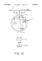
- FIG. (1) is a front sectional view of a single preferred illuminator/camera assembly embodiment including an integrating Lambertian cylinder, enclosing lamp means and packaged in a housing which also contains and positions light-conducting means and image capture means (CCPD and associated optical means); while FIGS. 1A, 1B functionally illustrate such a cylinder and FIG. 1C shows such in combination with camera means;
- CCPD light-conducting means and image capture means
- FIG. (2) is a side-sectional view of a pair of like (twin-) illuminator/camera assemblies, with a pair of said cylinders, plus associated light-conducting means and image capture means, combined in a single IMAGER unit;
- FIG. (3) is a plan view of the twin arrangement of FIG. 2;
- FIG. (4) is an isometric view showing the front section of the camera shown in FIGS. 1-3;
- FIG. (5) is a schematic showing an imaging optical path for the camera of FIGS. 1-4;
- FIG. (6) schematically illustrates the aforementioned phenomenon of "centration error” and how it arises.
- FIG. (7) shows an isometric view of an alternative construction of an illuminator/camera (IMAGER) assembly in which a single glass block is employed to perform the functions of multiple glass blocks and mirrors.
- IMAGER illuminator/camera
- FIG. 1A simplistically shows an integrating Lambertian illumination cylinder unit C that is here preferred.
- Unit C will be understood to provide a light source that we have characterized as a Lambertian emitter distributed in a linear fashion.
- the output will appear as an incoherent source of monochromatic or panchromatic light emitted from an aperture T-S which has a relatively high aspect ratio (length to width ratio).
- the internal source(s) of luminance may be derived from such light sources as; incandescent bulbs, fluorescent lamps, gas discharge lamps, laser sources of other optically pumped emitters or from other luminous sources such as the output of a fiberoptic bundle--but here we prefer tungsten-halogen lamps.
- the placement of the source(s) is not critical, but may impact output uniformity.
- the intensity profile as a function of distance from the exit aperture very uniform and predictable and allows for a considerable "depth of illumination”.
- Components comprising the disclosed light source are readily available, easily manufactured from standard materials and do not rely on the
- FIGS. 1A, 1B A typical application for this light source is viewed in FIGS. 1A, 1B where:
- a hollow cylinder is provided with an aperture T-S cut along its length and circumferentially offset from a series of circular apertures which allow for the intromission of an array of incandescent light sources, L;
- the cylinder interior is coated with a high reflectivity Lambertian (diffuse) reflector-film;
- FIG. 1C This end view of the cylindrical source shows
- One of the (potentially many) light sources L used to illuminate the interior of the cavity and having multiple reflections before it exits the cylinder;
- the scan rate of the CCPD Camera is synchronized to the linear velocity of the object so as to take repeated "slices" of the object as it passes in front of the light source.
- this light source C Lambertian characteristics of this light source C; it inherently produces a uniform and glare-free means of illumination --and no focusing of illumination beam needed.
- the luminous sources (lamps) L in the cylinder can be selected to optimize system performance by using incandescent sources if an "Infrared-rich” light source is needed; fluorescent, if a "cooler” light source is needed; Ultra-Violet if a UV source is required; or any selection of other possibly monochromatic sources depending on the system application and demands.
- the output from all such sources of internal luminance is integrated in the cylinder to produce a single, uniform beam of light.
- Cylinder interior may be coated with a phosphorescent material (instead of the white reflecting material) which, upon excitation from an appropriate source, will provide a similar uniform output.
- a phosphorescent material instead of the white reflecting material
- the color selection of the phosphor may also lend itself to optimizing system performance.
- FIG. 1 First Embodiment, FIG. 1:
- FIG. 1 shows such an integrating Lambertian cylinder C and associated CCPD, lens etc., all packaged into one housing H' which is also adapted--according to this embodiment--to house optical guide means gm (glass block GB, GB, and associated mirror surface M) which optically couples aperture T-S to the imaging site where documents d are driven past.
- housing H' is adapted to protrude thru a transport platform MB so that only guide means gm lie above MB, while the rest of housing H' lies below (on the other side).
- FIGS. 2-4 depict a twin illumination/camera (IMAGER) unit system according to our preferred embodiment.
- IMAGER twin illumination/camera
- This IMAGER will be understood as consisting of two essentially identical camera assemblies (e.g. each as in FIG. 1) combined into a single system, one for the front of the document, one for the rear, [like elements in each camera are differentiated by the subscript "f" for "front” and “r” for “rear”.]
- This IMAGER comprises an integrating housing H, with two source-integrating cylindrical Lambertian cavities C therein.
- Housing H incorporates (packages) both illumination means, camera means, and associated light-coupling and image-coupling means (e.g. glass blocks GB and image mirrors M) for directing light from each cavity C to passing documents and likewise coupling the images reflected from the documents back through the cavity to imaging means (e.g. CCPD) coupled thereto.
- illumination means e.g. glass blocks GB and image mirrors M
- Each "integrating" cavity C consists of a cylindrical cavity, open (and capped) at one end and closed at the other, fashioned in housing H.
- the open end is closed by separate cover CP, permanently fastened to housing H, thus forming a true closed cylindrical cavity.
- Glass blocks GB fitted onto housing H, (preferably two for each cavity, see below and FIG. 3), act to optically guide illumination from cavity C to the imaging site and back.
- Image mirrors M also fitted to housing H, act to optically reflect and direct the image of the document back into housing H, through cavity C and, via image-forming lens means LL, onto imaging means CCPD.
- glass blocks GB and mirrors M will be seen to advantageously allow source-integrating means, illumination sites and camera hardware to be remotely mounted from the imaging site and physically isolated therefrom, (e.g. preferably under platform MB), thus preventing the entry of dust and debris into this hardware, facilitating repair-access, and isolating the units thermally and optically.
- one cylindrical cavity, of may be used for illumination/detection of the front face of the document, while a second like cavity, Cr, may be used for illumination of the rear face in like manner.
- Each cylindrical cavity C contains an array of one or more lamps L each preferably a like tungsten-halogen incandescent lamp. Our preferred embodiment shows five such lamps; however more or less, of varying power, could be employed depending upon the requirements of any given application.
- a long, narrow illumination slit T-S adapted to admit a maximum of "integrated light: from the interior of the cylinder C to respective glass blocks GB, GB and thence to the face of the document d to be illuminated.
- the image of the illuminated document passes back thru glass blocks GB-GB, then it is reflected by image mirror M back through the same illumination-slit T-S, through the cavity C and beyond, into a second, smaller imaging-slit ts, and thence to lens means LL and camera (CCPD) means.
- this image aperture ts should have a width approximately that of the CCPD and should be arranged to pass only reflected images (from documents)--essentially barring passage of any raw, non-image light from the cavity; i.e. aperture ts will be "dark", or opaque to all direct illumination from its cavity.
- aperture ts will preferably have anti-reflective sides (e.g. toughened, or with fins, etc.) and have a rather collimating length dt (e.g. here 3-4" or more, see FIGS. 1, 5; where cavity wall is about 1/4" thick).
- opposing illuminating-aperture T-S will include glass blocks which have anti-reflective ends facing the cavity, to minimize reflection to imaging-aperture ts.
- FIG. (3 that two glass blocks GB are shown disposed at equal angles ⁇ about the optical centerline of the camera.
- optimal and consistent illumination across the full width of the track is a function of track width, size and width of glass blocks GB and pf the distance between them, the type and intensity of illumination and the type and characteristics of the glass block material.
- the illumination may be advantageously shaped and formed in the area of the imaging site by increasing or decreasing angle ⁇ to produce the most consistent result. Workers in the art will readily understand that the multiple variables at play in this area make analysis of the construction most complex, and that the best angle for ⁇ (if other than 0) will be found by careful experiment. This is not to specify that angle ⁇ need necessarily have any value other than 0, but rather to say that illumination may be beneficially impacted by careful experiment and control of this angle.
- the housing H containing cavities C is preferably made of aluminum alloy, and the interior surfaces which form integrating cavities C are preferably at once highly reflective and also highly diffusing, a dual property we characterize as "Lambertian reflectance". Such reflecting surfaces will also diffuse and integrate the light from all the individual lamp means and, by means of many internal reflection paths, produce at the glass blocks GB, GB non-directional illumination of uniform intensity in which the individual light sources are no longer discernable, and their contributions are well intermixed and "integrated".
- Such a reflecting surface is preferably obtained by coating with a highly diffuse reflecting medium having a matte finish.
- a highly diffuse reflecting medium having a matte finish.
- Barium Sulfate carried in an inorganic binder; it may readily be applied to the cavity (preferred aluminum alloy) surfaces to provide a nearly perfect Lambertian surface at moderate cost.
- housing H is preferably unitary, it may also be divided (e.g. one front, one Rear; or unitary with separate front, rear optical guide means).
- FIG. (7 An alternative construction is also possible as shown in FIG. (7, wherein the two glass blocks GB, GB, described above, are replaced by a single glass block, SGB,--one for each illuminating cavity C.
- Such glass blocks will be understood as provided with mirror coatings and as serving as an illumination-coupling means for conveying light from the cylinder C to the face of the document, and also for conveying the image of the document back through the cylinder to the lens and CCPD means.
- This alternative construction will be understood to be identical in all respects to that already described, and to be described subsequently, save only the differing detail of the construction and application of the single glass block.
- Such a construction may produce a camera assembly with fewer parts (such as mirrors, mounts and the like) and a smaller profile in the area above the cylinder.
- documents d may be transported above one surface of a machine base-plate structure or platform MB, past the site of image capture (e.g. between front and rear glass block means GB as in FIG. 3), while associated front and rear integrating cylinders of, Cr, lamp means, lens means and CCPD means are located below base-plate MB and isolated from one another, from affecting documents and from the entry and build up of dust, debris and the like.
- Such remote disposition of lamp, lens and CCPD means also permits them to be easily accessed for service and repair without need to disturb components on the upper face of base-plate MB, where typically extensive high-speed rotating machine elements are disposed to drive and direct documents d.
- Illumination within each cylinder cavity C is provided, preferably, by an array of tungsten-halogen incandescent lamps L, which are chosen for their well-adapted spectral characteristics, ready availability, moderate cost and excellent reliability. Further, by using multiple, low-cost lamp means, available in a wide range of illumination outputs within the same interchangeable package style, we may custom-tailor illumination to a given set of circumstances by selecting more or fewer lamps of varying output to give the exact intensity of illumination desired. Additionally, the use of multiple lamps permits us to introduce some redundancy into our system--e-g.
- optical sensor OS which views some part of the cylinder wall (not looking directly at any of the lamps) and directs its output signal, OSS, from that sensor to some signal-conditioning means (not shown, but well understood in the art).
- FIG. (2) optical sensors OS are shown mounted in each cover plate CP, (sensor Cr in cover Cpr, sensor Of in cover CPf). But this is merely a schematic representation--the sensor may be mounted in any convenient position where it has an unobstructed view of the wall of the cavity C, since the highly integrating nature of the cavity means that any part of its wall has the same brightness as any other part.
- the signal conditioning circuitry should have been initially calibrated against a known reference; it can then be used to optimally adjust lamp current to give the right amount of light. In this way, optimal illumination may be derived, to secure the best and most consistent response from the CCPD, while at the same time minimizing lamp current (thus maximizing lamp life, as well-understood by workers regarding incandescent lamps) and minimizing power consumption and therefore undesired heating of the camera assembly.
- tungsten halogen lamps which we find give adequate-illumination for the particular application we have n mind, (e.g. where document speed is the order of 300 ips.)
- the total illumination required may be greater or less, depending upon document speed, and this may be accommodated by using lamps of the same package dimensions but of higher or lower power, or by adding/omitting one or more of the lamps, or a combination of both.
- a feature of advantage of the integrating cylinder design is its ability to integrate the output of multiple point-sources of illumination to the point where the individual sources are not discernable in the final output of the cylinder. This effect holds true for a wide range of combinations of lamp power and number of lamps.
- the illumination means For ease of construction and service, we prefer to construct the illumination means as a separable assembly, containing lamps, mounting means, electrical connection means and cooling means in a single, integrated assembly. In this manner, when warned of a lamp failure, an attendant need not take time to determine which lamp has failed or why--but may simply remove and replace the entire illumination assembly with a minimum of delay. Later, the removed assembly may be re-lamped and serviced at some convenient opportunity. In this way, we ensure maximum productive uninterrupted use of the document-processing system.
- Lamps of this type typically convert a considerable part of their power consumption to heat, and a large part of this is transmitted through the body of the lamp to the mounting and connection means.
- our preferred separable lamp assembly is provided with multiple cooling fins, f--f, so disposed as to lie within the airflow of a separate cooling fan, (not shown, but well understood in the art).
- a certain amount of heat is also generated in the main housing H, by conduction from the lamp assemblies and also as a result of reflective loss at the inner surfaces of cylinders C.
- Housing H is therefore also preferably provided (e.g. FIG. 4 with cooling fins f--f, disposed to lie within the airflow of some (e.g. the same) cooling fan (e.g. see FIG. 1).
- a trimming optical filter (FiL--details not shown, but well understood in the art) to selectively shape the spectral characteristics of the light falling on the CCPD to optimize CCPD response.
- a filter where employed, would preferably be placed as close as possible to the lens means LL, since the image is at its smallest at this point and this will minimize the use of costly custom-coated optical filter materials.
- the means and methods disclosed herein are also applicable to other, related illumination tasks, both in other imaging-type systems and to meet other requirements for illumination.
Landscapes
- Physics & Mathematics (AREA)
- Optics & Photonics (AREA)
- Engineering & Computer Science (AREA)
- Multimedia (AREA)
- Signal Processing (AREA)
- General Physics & Mathematics (AREA)
- Facsimile Scanning Arrangements (AREA)
Abstract
Description
Claims (37)
Priority Applications (3)
| Application Number | Priority Date | Filing Date | Title |
|---|---|---|---|
| US08/486,489 US5519513A (en) | 1994-02-07 | 1995-06-07 | Techniques for illuminating objects |
| US08/643,393 US5717504A (en) | 1994-02-07 | 1996-05-06 | Apparatus for illuminating documents |
| US09/010,287 US6178014B1 (en) | 1994-02-07 | 1998-01-21 | Methods for illuminating documents |
Applications Claiming Priority (2)
| Application Number | Priority Date | Filing Date | Title |
|---|---|---|---|
| US08/192,964 US5453849A (en) | 1994-02-07 | 1994-02-07 | Integrating cylinder for object illumination |
| US08/486,489 US5519513A (en) | 1994-02-07 | 1995-06-07 | Techniques for illuminating objects |
Related Parent Applications (1)
| Application Number | Title | Priority Date | Filing Date |
|---|---|---|---|
| US08/192,964 Division US5453849A (en) | 1994-02-07 | 1994-02-07 | Integrating cylinder for object illumination |
Related Child Applications (1)
| Application Number | Title | Priority Date | Filing Date |
|---|---|---|---|
| US08/643,393 Division US5717504A (en) | 1994-02-07 | 1996-05-06 | Apparatus for illuminating documents |
Publications (1)
| Publication Number | Publication Date |
|---|---|
| US5519513A true US5519513A (en) | 1996-05-21 |
Family
ID=22711749
Family Applications (4)
| Application Number | Title | Priority Date | Filing Date |
|---|---|---|---|
| US08/192,964 Expired - Lifetime US5453849A (en) | 1994-02-07 | 1994-02-07 | Integrating cylinder for object illumination |
| US08/486,489 Expired - Fee Related US5519513A (en) | 1994-02-07 | 1995-06-07 | Techniques for illuminating objects |
| US08/643,393 Expired - Lifetime US5717504A (en) | 1994-02-07 | 1996-05-06 | Apparatus for illuminating documents |
| US09/010,287 Expired - Fee Related US6178014B1 (en) | 1994-02-07 | 1998-01-21 | Methods for illuminating documents |
Family Applications Before (1)
| Application Number | Title | Priority Date | Filing Date |
|---|---|---|---|
| US08/192,964 Expired - Lifetime US5453849A (en) | 1994-02-07 | 1994-02-07 | Integrating cylinder for object illumination |
Family Applications After (2)
| Application Number | Title | Priority Date | Filing Date |
|---|---|---|---|
| US08/643,393 Expired - Lifetime US5717504A (en) | 1994-02-07 | 1996-05-06 | Apparatus for illuminating documents |
| US09/010,287 Expired - Fee Related US6178014B1 (en) | 1994-02-07 | 1998-01-21 | Methods for illuminating documents |
Country Status (1)
| Country | Link |
|---|---|
| US (4) | US5453849A (en) |
Cited By (17)
| Publication number | Priority date | Publication date | Assignee | Title |
|---|---|---|---|---|
| US5717504A (en) * | 1994-02-07 | 1998-02-10 | Unisys Corp. | Apparatus for illuminating documents |
| US5790281A (en) * | 1996-10-02 | 1998-08-04 | Xerox Corporation | Method of correcting the measured reflectance of an image acquired by an image acquisition device for the integrating cavity effect |
| WO1999042900A1 (en) * | 1998-02-06 | 1999-08-26 | Videometer Aps | An apparatus and a method of recording an image of an object |
| US6033086A (en) * | 1998-04-30 | 2000-03-07 | Hewlett-Packard Company | Compact illumination system for image scanner |
| EP0987872A2 (en) * | 1998-09-14 | 2000-03-22 | Hewlett-Packard Company | Scan line illumination system utilizing hollow reflector |
| US6160906A (en) * | 1998-06-01 | 2000-12-12 | Motorola, Inc. | Method and apparatus for visually inspecting an object |
| US20030067545A1 (en) * | 2001-08-29 | 2003-04-10 | L'oreal | Device and method for acquiring an image of a portion of the human body |
| US20030090749A1 (en) * | 2001-11-14 | 2003-05-15 | Branson David E. | Illumination system for illuminating a scan region on an object |
| US20040004669A1 (en) * | 2002-07-05 | 2004-01-08 | Po-Hua Fang | Light-focusing for image-gathering device and method |
| US20040057097A1 (en) * | 2002-09-24 | 2004-03-25 | Veutron Corporation | Optical device of scanner |
| US6749120B2 (en) * | 2000-12-11 | 2004-06-15 | Cpo Technologies Corp. | Method and apparatus for scanning electronic barcodes |
| US20060067078A1 (en) * | 2004-09-28 | 2006-03-30 | Goldeneye, Inc. | Light recycling illumination systems having restricted angular output |
| US20060091825A1 (en) * | 2004-11-01 | 2006-05-04 | Gil Abramovich | Reconfigurable linescan illumination |
| US20080247172A1 (en) * | 2004-09-28 | 2008-10-09 | Goldeneye, Inc. | Light recycling illumination systems having restricted angular output |
| US20110110079A1 (en) * | 2009-11-11 | 2011-05-12 | Cheng-Chao Jong | Light guide illumination device |
| US20130271764A1 (en) * | 2010-09-30 | 2013-10-17 | Carl Zeiss Microscopy Gmbh | Measurement devices and apparatuses for spectroscopic examination of samples |
| US20140078730A1 (en) * | 2012-09-18 | 2014-03-20 | Wavien, Inc. | Lamp system having parabolic reflector with two reflections for recycling light |
Families Citing this family (19)
| Publication number | Priority date | Publication date | Assignee | Title |
|---|---|---|---|---|
| US5548120A (en) * | 1994-11-14 | 1996-08-20 | Eastman Kodak Company | Linear integrating cavity light source for infra-red illumination of sensitized media |
| US5652665A (en) * | 1995-09-08 | 1997-07-29 | Umax Data System Inc. | Transparency adapter for flatbed scanners |
| US6607794B1 (en) | 1998-04-16 | 2003-08-19 | Alliedsignal Inc. | Light-reflecting molded articles and methods of making the same |
| US6224237B1 (en) | 1998-04-16 | 2001-05-01 | Honeywell International Inc. | Structure for achieving a linear light source geometry |
| US6186649B1 (en) | 1998-04-16 | 2001-02-13 | Honeywell International Inc. | Linear illumination sources and systems |
| US6754037B1 (en) * | 1999-07-28 | 2004-06-22 | Storage Technology Corporation | Small library horseshoe architecture |
| EP1321902B1 (en) * | 2001-12-20 | 2015-08-12 | MEI, Inc. | Currency acceptor and light source for use therein |
| US6995355B2 (en) | 2003-06-23 | 2006-02-07 | Advanced Optical Technologies, Llc | Optical integrating chamber lighting using multiple color sources |
| US20070051883A1 (en) * | 2003-06-23 | 2007-03-08 | Advanced Optical Technologies, Llc | Lighting using solid state light sources |
| US20070138978A1 (en) * | 2003-06-23 | 2007-06-21 | Advanced Optical Technologies, Llc | Conversion of solid state source output to virtual source |
| US7261730B2 (en) * | 2003-11-14 | 2007-08-28 | Lumerx, Inc. | Phototherapy device and system |
| US20050231958A1 (en) * | 2004-02-09 | 2005-10-20 | Gregory Cutler | Illumination system with improved optical efficiency |
| US7144131B2 (en) * | 2004-09-29 | 2006-12-05 | Advanced Optical Technologies, Llc | Optical system using LED coupled with phosphor-doped reflective materials |
| US7715063B2 (en) * | 2005-03-31 | 2010-05-11 | Xerox Corporation | CVT integrated illuminator |
| US7755811B2 (en) * | 2005-06-30 | 2010-07-13 | Xerox Corporation | Document illuminator |
| US7365991B2 (en) * | 2006-04-14 | 2008-04-29 | Renaissance Lighting | Dual LED board layout for lighting systems |
| CA2783147A1 (en) * | 2009-12-08 | 2011-06-16 | 3M Innovative Properties Company | Illumination apparatus and methods for a biological growth plate scanner |
| DE102013219830B4 (en) * | 2013-09-30 | 2021-11-11 | Carl Zeiss Spectroscopy Gmbh | Optical device for reflection measurement under diffuse lighting and method for optimizing such, and use of the device |
| US11172107B1 (en) * | 2020-10-22 | 2021-11-09 | Charles Hoeppner | Optical path alignment guide |
Citations (4)
| Publication number | Priority date | Publication date | Assignee | Title |
|---|---|---|---|---|
| US4868383A (en) * | 1988-09-08 | 1989-09-19 | Eastman Kodak Company | Linear integrating cavity light source used for generating an intense beam of light |
| US5079678A (en) * | 1990-12-24 | 1992-01-07 | Eastman Kodak Company | Integrating light source utilizing a fluorescing reflector for improved light emission and color balance |
| US5155776A (en) * | 1989-10-10 | 1992-10-13 | Unisys Corp. | Filtering illumination for image lift |
| US5274228A (en) * | 1992-06-01 | 1993-12-28 | Eastman Kodak Company | Linear light source/collector with integrating cylinder and light pipe means |
Family Cites Families (2)
| Publication number | Priority date | Publication date | Assignee | Title |
|---|---|---|---|---|
| US5453849A (en) * | 1994-02-07 | 1995-09-26 | Unisys Corporation | Integrating cylinder for object illumination |
| US5386267A (en) * | 1994-02-16 | 1995-01-31 | Eastman Kodak Company | Light integrating cavity for a film scanner |
-
1994
- 1994-02-07 US US08/192,964 patent/US5453849A/en not_active Expired - Lifetime
-
1995
- 1995-06-07 US US08/486,489 patent/US5519513A/en not_active Expired - Fee Related
-
1996
- 1996-05-06 US US08/643,393 patent/US5717504A/en not_active Expired - Lifetime
-
1998
- 1998-01-21 US US09/010,287 patent/US6178014B1/en not_active Expired - Fee Related
Patent Citations (4)
| Publication number | Priority date | Publication date | Assignee | Title |
|---|---|---|---|---|
| US4868383A (en) * | 1988-09-08 | 1989-09-19 | Eastman Kodak Company | Linear integrating cavity light source used for generating an intense beam of light |
| US5155776A (en) * | 1989-10-10 | 1992-10-13 | Unisys Corp. | Filtering illumination for image lift |
| US5079678A (en) * | 1990-12-24 | 1992-01-07 | Eastman Kodak Company | Integrating light source utilizing a fluorescing reflector for improved light emission and color balance |
| US5274228A (en) * | 1992-06-01 | 1993-12-28 | Eastman Kodak Company | Linear light source/collector with integrating cylinder and light pipe means |
Non-Patent Citations (2)
| Title |
|---|
| Webster, S. C. , "Novel, lightweight, and low-cost illumination system for line-scan cameras," Optical Engineering (Aug. 1992) vol. 31, No. 8, pp.1654-1657. |
| Webster, S. C. , Novel, lightweight, and low cost illumination system for line scan cameras, Optical Engineering (Aug. 1992) vol. 31, No. 8, pp.1654 1657. * |
Cited By (27)
| Publication number | Priority date | Publication date | Assignee | Title |
|---|---|---|---|---|
| US5717504A (en) * | 1994-02-07 | 1998-02-10 | Unisys Corp. | Apparatus for illuminating documents |
| US5790281A (en) * | 1996-10-02 | 1998-08-04 | Xerox Corporation | Method of correcting the measured reflectance of an image acquired by an image acquisition device for the integrating cavity effect |
| WO1999042900A1 (en) * | 1998-02-06 | 1999-08-26 | Videometer Aps | An apparatus and a method of recording an image of an object |
| US6033086A (en) * | 1998-04-30 | 2000-03-07 | Hewlett-Packard Company | Compact illumination system for image scanner |
| US6160906A (en) * | 1998-06-01 | 2000-12-12 | Motorola, Inc. | Method and apparatus for visually inspecting an object |
| US6404912B1 (en) | 1998-06-01 | 2002-06-11 | Motorola, Inc. | Method and apparatus for visually inspecting an object |
| MY120808A (en) * | 1998-06-01 | 2005-11-30 | Freescale Semiconductor Inc | Method and apparatus for visually inspecting an object |
| EP0987872A2 (en) * | 1998-09-14 | 2000-03-22 | Hewlett-Packard Company | Scan line illumination system utilizing hollow reflector |
| EP0987872A3 (en) * | 1998-09-14 | 2002-05-02 | Hewlett-Packard Company, A Delaware Corporation | Scan line illumination system utilizing hollow reflector |
| US6749120B2 (en) * | 2000-12-11 | 2004-06-15 | Cpo Technologies Corp. | Method and apparatus for scanning electronic barcodes |
| US20030067545A1 (en) * | 2001-08-29 | 2003-04-10 | L'oreal | Device and method for acquiring an image of a portion of the human body |
| US20030090749A1 (en) * | 2001-11-14 | 2003-05-15 | Branson David E. | Illumination system for illuminating a scan region on an object |
| US7543966B2 (en) | 2001-11-14 | 2009-06-09 | Hewlett-Packard Development Company, L.P. | Illumination system for illuminating a scan region on an object |
| US7859727B2 (en) * | 2002-07-05 | 2010-12-28 | Po-Hua Fang | Image-gathering apparatus and method |
| US20040004669A1 (en) * | 2002-07-05 | 2004-01-08 | Po-Hua Fang | Light-focusing for image-gathering device and method |
| US20070070462A1 (en) * | 2002-09-10 | 2007-03-29 | Yin-Chun Huang | Optical device of scanner |
| US8111434B2 (en) * | 2002-09-10 | 2012-02-07 | Transpacific Systems, Llc | Optical device of scanner |
| US7242502B2 (en) * | 2002-09-24 | 2007-07-10 | Yin-Chun Huang | Optical device of scanner |
| US20040057097A1 (en) * | 2002-09-24 | 2004-03-25 | Veutron Corporation | Optical device of scanner |
| US7370993B2 (en) * | 2004-09-28 | 2008-05-13 | Goldeneye, Inc. | Light recycling illumination systems having restricted angular output |
| US20080247172A1 (en) * | 2004-09-28 | 2008-10-09 | Goldeneye, Inc. | Light recycling illumination systems having restricted angular output |
| US20060067078A1 (en) * | 2004-09-28 | 2006-03-30 | Goldeneye, Inc. | Light recycling illumination systems having restricted angular output |
| US7168822B2 (en) * | 2004-11-01 | 2007-01-30 | The Regents Of The Univeristy Of Michigan | Reconfigurable linescan illumination |
| US20060091825A1 (en) * | 2004-11-01 | 2006-05-04 | Gil Abramovich | Reconfigurable linescan illumination |
| US20110110079A1 (en) * | 2009-11-11 | 2011-05-12 | Cheng-Chao Jong | Light guide illumination device |
| US20130271764A1 (en) * | 2010-09-30 | 2013-10-17 | Carl Zeiss Microscopy Gmbh | Measurement devices and apparatuses for spectroscopic examination of samples |
| US20140078730A1 (en) * | 2012-09-18 | 2014-03-20 | Wavien, Inc. | Lamp system having parabolic reflector with two reflections for recycling light |
Also Published As
| Publication number | Publication date |
|---|---|
| US5453849A (en) | 1995-09-26 |
| US6178014B1 (en) | 2001-01-23 |
| US5717504A (en) | 1998-02-10 |
Similar Documents
| Publication | Publication Date | Title |
|---|---|---|
| US5519513A (en) | Techniques for illuminating objects | |
| EP0873551B1 (en) | Illumination system for ocr of indicia on a substrate | |
| US6488389B2 (en) | Image generator having an improved illumination system | |
| US6246464B1 (en) | Illumination system | |
| JP3707810B2 (en) | Scanner adapter | |
| EP0308162A2 (en) | Optical system for fingerprint imaging | |
| US6191872B1 (en) | Illuminator with light source arrays | |
| US6727974B2 (en) | Photograph printing device, electronic image input device, film scanner, scratch recognition method, memory medium recording scratch recognition program, and image restoration method | |
| US20030202250A1 (en) | Array lens, lighting optical system, optical unit and imaging apparatus | |
| US5367386A (en) | Image scanning apparatus adapted for thermally and optically isolating imaging components | |
| US5825945A (en) | Document imaging with illumination from lambertian surfaces | |
| US5491336A (en) | Document illumination with Lambertian cavity | |
| EP0100610B1 (en) | Illumination system | |
| US5617152A (en) | Projector system for video and computer generated information | |
| EP0631434A1 (en) | Projector | |
| CN213933562U (en) | Bottle bottom shooting device and bottle bottom detection equipment | |
| US4979813A (en) | Opaque projector | |
| US5767990A (en) | Illumination device for film image scanning device | |
| US5701361A (en) | Adjusting illumination for image lift | |
| JP3089145B2 (en) | Optical reader | |
| US5144457A (en) | Integrated imaging assembly | |
| US6249502B1 (en) | Optical recording head | |
| EP0644682B1 (en) | A scanning apparatus | |
| JP2844547B2 (en) | Coin image input device | |
| US20010005317A1 (en) | Diffusive optical element, illumination optical system, and image-shooting apparatus |
Legal Events
| Date | Code | Title | Description |
|---|---|---|---|
| FPAY | Fee payment |
Year of fee payment: 4 |
|
| LAPS | Lapse for failure to pay maintenance fees | ||
| FP | Lapsed due to failure to pay maintenance fee |
Effective date: 20040521 |
|
| AS | Assignment |
Owner name: UNISYS CORPORATION,PENNSYLVANIA Free format text: JUNIOR SECURITY RELEASE;ASSIGNOR:DEUTSCHE BANK TRUST COMPANY AMERICAS;REEL/FRAME:023882/0613 Effective date: 20100201 Owner name: UNISYS CORPORATION,PENNSYLVANIA Free format text: PRIORITY SECURITY RELEASE;ASSIGNOR:DEUTSCHE BANK TRUST COMPANY AMERICAS;REEL/FRAME:023905/0218 Effective date: 20100201 Owner name: UNISYS CORPORATION, PENNSYLVANIA Free format text: PRIORITY SECURITY RELEASE;ASSIGNOR:DEUTSCHE BANK TRUST COMPANY AMERICAS;REEL/FRAME:023905/0218 Effective date: 20100201 Owner name: UNISYS CORPORATION, PENNSYLVANIA Free format text: JUNIOR SECURITY RELEASE;ASSIGNOR:DEUTSCHE BANK TRUST COMPANY AMERICAS;REEL/FRAME:023882/0613 Effective date: 20100201 |
|
| AS | Assignment |
Owner name: BURROUGHS PAYMENT SYSTEMS, INC.,MICHIGAN Free format text: ASSIGNMENT OF ASSIGNORS INTEREST;ASSIGNOR:UNISYS CORPORATION;REEL/FRAME:024006/0219 Effective date: 20100201 Owner name: BURROUGHS PAYMENT SYSTEMS, INC., MICHIGAN Free format text: ASSIGNMENT OF ASSIGNORS INTEREST;ASSIGNOR:UNISYS CORPORATION;REEL/FRAME:024006/0219 Effective date: 20100201 |
|
| AS | Assignment |
Owner name: PNC BANK, NATIONAL ASSOCIATION, AS AGENT, PENNSYLV Free format text: SECURITY AGREEMENT;ASSIGNOR:BURROUGHS PAYMENT SYSTEMS, INC.;REEL/FRAME:025591/0665 Effective date: 20101223 |
|
| AS | Assignment |
Owner name: BURROUGHS, INC. (FORMERLY KNOWN AS BURROUGHS PAYME Free format text: RELEASE OF SECURITY INTEREST IN PATENTS;ASSIGNOR:PNC BANK, NATIONAL ASSOCIATION;REEL/FRAME:039897/0823 Effective date: 20150130 |
|
| STCH | Information on status: patent discontinuation |
Free format text: PATENT EXPIRED DUE TO NONPAYMENT OF MAINTENANCE FEES UNDER 37 CFR 1.362 |