US5509648A - Document separation/detection technique - Google Patents
Document separation/detection technique Download PDFInfo
- Publication number
- US5509648A US5509648A US08/451,800 US45180095A US5509648A US 5509648 A US5509648 A US 5509648A US 45180095 A US45180095 A US 45180095A US 5509648 A US5509648 A US 5509648A
- Authority
- US
- United States
- Prior art keywords
- items
- vacuum
- suction
- pressure
- debris
- Prior art date
- Legal status (The legal status is an assumption and is not a legal conclusion. Google has not performed a legal analysis and makes no representation as to the accuracy of the status listed.)
- Expired - Lifetime
Links
Images


Classifications
-
- B—PERFORMING OPERATIONS; TRANSPORTING
- B65—CONVEYING; PACKING; STORING; HANDLING THIN OR FILAMENTARY MATERIAL
- B65H—HANDLING THIN OR FILAMENTARY MATERIAL, e.g. SHEETS, WEBS, CABLES
- B65H7/00—Controlling article feeding, separating, pile-advancing, or associated apparatus, to take account of incorrect feeding, absence of articles, or presence of faulty articles
- B65H7/02—Controlling article feeding, separating, pile-advancing, or associated apparatus, to take account of incorrect feeding, absence of articles, or presence of faulty articles by feelers or detectors
- B65H7/06—Controlling article feeding, separating, pile-advancing, or associated apparatus, to take account of incorrect feeding, absence of articles, or presence of faulty articles by feelers or detectors responsive to presence of faulty articles or incorrect separation or feed
- B65H7/12—Controlling article feeding, separating, pile-advancing, or associated apparatus, to take account of incorrect feeding, absence of articles, or presence of faulty articles by feelers or detectors responsive to presence of faulty articles or incorrect separation or feed responsive to double feed or separation
- B65H7/125—Controlling article feeding, separating, pile-advancing, or associated apparatus, to take account of incorrect feeding, absence of articles, or presence of faulty articles by feelers or detectors responsive to presence of faulty articles or incorrect separation or feed responsive to double feed or separation sensing the double feed or separation without contacting the articles
-
- G—PHYSICS
- G06—COMPUTING; CALCULATING OR COUNTING
- G06K—GRAPHICAL DATA READING; PRESENTATION OF DATA; RECORD CARRIERS; HANDLING RECORD CARRIERS
- G06K13/00—Conveying record carriers from one station to another, e.g. from stack to punching mechanism
- G06K13/02—Conveying record carriers from one station to another, e.g. from stack to punching mechanism the record carrier having longitudinal dimension comparable with transverse dimension, e.g. punched card
- G06K13/06—Guiding cards; Checking correct operation of card-conveying mechanisms
- G06K13/067—Checking presence, absence, correct position, or moving status of cards
-
- G—PHYSICS
- G06—COMPUTING; CALCULATING OR COUNTING
- G06K—GRAPHICAL DATA READING; PRESENTATION OF DATA; RECORD CARRIERS; HANDLING RECORD CARRIERS
- G06K13/00—Conveying record carriers from one station to another, e.g. from stack to punching mechanism
- G06K13/02—Conveying record carriers from one station to another, e.g. from stack to punching mechanism the record carrier having longitudinal dimension comparable with transverse dimension, e.g. punched card
- G06K13/08—Feeding or discharging cards
- G06K13/10—Feeding or discharging cards from magazine to conveying arrangement
- G06K13/107—Feeding or discharging cards from magazine to conveying arrangement using pneumatic means
-
- B—PERFORMING OPERATIONS; TRANSPORTING
- B65—CONVEYING; PACKING; STORING; HANDLING THIN OR FILAMENTARY MATERIAL
- B65H—HANDLING THIN OR FILAMENTARY MATERIAL, e.g. SHEETS, WEBS, CABLES
- B65H2515/00—Physical entities not provided for in groups B65H2511/00 or B65H2513/00
- B65H2515/30—Forces; Stresses
- B65H2515/34—Pressure, e.g. fluid pressure
-
- B—PERFORMING OPERATIONS; TRANSPORTING
- B65—CONVEYING; PACKING; STORING; HANDLING THIN OR FILAMENTARY MATERIAL
- B65H—HANDLING THIN OR FILAMENTARY MATERIAL, e.g. SHEETS, WEBS, CABLES
- B65H2553/00—Sensing or detecting means
- B65H2553/10—Sensing or detecting means using fluids, e.g. pneumatics
-
- B—PERFORMING OPERATIONS; TRANSPORTING
- B65—CONVEYING; PACKING; STORING; HANDLING THIN OR FILAMENTARY MATERIAL
- B65H—HANDLING THIN OR FILAMENTARY MATERIAL, e.g. SHEETS, WEBS, CABLES
- B65H2701/00—Handled material; Storage means
- B65H2701/10—Handled articles or webs
- B65H2701/19—Specific article or web
- B65H2701/1912—Banknotes, bills and cheques or the like
Definitions
- This invention relates to document detection systems, and particularly to those using a vacuum-separation method to identify and signal double documents and employing associated vacuum generating, coupling and sensing means. Particular attention is given to the use of such systems in high-speed document processing machinery.
- the additional thickness of a second document should produce a measurable change in signal.
- optical sensors are very susceptible to failure due to the high levels of dust and debris found around document processing machinery.
- the thickness of the document may be measured by means of one of a variety of sensors.
- the additional thickness of a second document should be measurable.
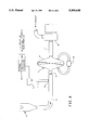
- FIGS. 1, 1A, 2 show a basic, simplified version of a vacuum-separation and sensing system of the type we first favored.
- the documents to be sensed are transported in a vertical position by transport means such as belts, pulleys and the like (not shown, but well understood in the art).
- the documents d are constrained to pass through a vacuum-separation manifold M which encloses the lower longitudinal edge of the document as it passes.
- This manifold incorporates two vacuum ports V1 and V2, each disposed on a respective side of the document.
- the two ports are connected to a common plenum chamber P, which is kept at negative pressure relative to the surrounding atmosphere by vacuum blower means B, (or the like) connected to plenum P by hose means H.
- a differential pressure switch S1 Connected to a port Q provided in the wall of hose means H is a differential pressure switch S1 which compares the pressure within the hose to the ambient atmospheric pressure.
- both vacuum ports V1 and V2 are open and unobscured, and air may freely flow into them under the influence of blower means B.
- the pressure differential between the inside of hose H and the surrounding atmosphere is "LOW"( ⁇ P L ).
- switch S1 is converted to an electrical signal, which is processed by signal-conditioning circuitry (not shown, but familiar to workers in the art) and provides to the controlling systems of the (check-sorting) machine an indication that a "double" has been detected.
- the controlling systems can then direct the suspected “double” to a holding area of the machine, without further processing, and alert the machine operator, who may investigate the item manually to correct or otherwise resolve the "double".
- Increasing document speeds have reduced the time available for a "doubles-detect" system to operate on a passing document and determine whether it is a "double".
- the Unisys DP1800 check sorting machine operates at a nominal track speed of 300 inches per second (ips, or 7.62 meters per second), and may operate with documents with a minimum length of 5.75 inches (11.4 centimeters).
- the time available to operate on a document e.g., to separate?
- Future developments are likely to increase document speed to as much as 400 ips (10.1 metres per second), with a corresponding reduction in time available for a sensor to make its determination.
- blower B For the DP1800 product, for example, would be rated to flow 30 cubic feet of air per minute and provide a maximum vacuum of 30 inches water gauge. These high airflows and vacuums would be required to ensure that the "double" is separated within the manifold M as quickly and securely as possible, even when the documents consist of heavier paper stock with higher resistance to "bending".
- This material may consist of paper fragments and dust, generated by the friction of document-driving elements or from the cut and sheared edges of the paper itself, as well as rubber and plastic particles shed from the driving elements (e.g., rolls, belts and the like, as well understood by workers in the art).
- Paper handling business machines e.g., Unisys check processors
- the vacuum is generated by vacuum pumps or blowers. These pumps/blowers require filtration of the air they move to protect their internal moving components from damage from dust/dirt in the air. Additionally, any exhaust air must be filtered to prevent contamination of the customer's office environment.
- the air filtration systems used are "barrier type” i.e., fiberglass or porous filter paper of some type. These require frequent field service maintenance for cleaning or replacement. In a high volume site for a Unisys DP1800 document processor, these filters typically require replacement twice a week. This frequent servicing by skilled field engineers adds substantially to the maintenance cost of this type business machine.
- cyclone paper dust collector can contain relatively large amounts of dust in its bunker, and so reduce the required frequency of maintenance.
- using a cyclone filter/blower embodiment can reduce frequency of service from twice a week to once every 3 months (or 1:24 ratio); and there are other advantages, such as:
- sensing port Q is moved further down hose H from manifold M to provide an effective column of air within hose H between manifold M and sensing port Q.
- the mass and volume of this column can act as a dynamic damper for pressure variations travelling there along, and can attenuate the magnitude of such pulses as they travel from manifold M to sensing port Q. In this way, the impact of such pulses at pressure switch S1 may be reduced, though not entirely eliminated.
- FIG. 2 shows modifications in the FIG. 1 arrangement for addressing some or all of foregoing concerns.
- the system is altered by addition of a mechanical air filter F in hose H, and provision for adjusting the airflow through hose H is made by adding a variable orifice R at the entrance to air filter F.
- the air filter serves to separate dust and debris from the air stream before it enters blower B, and to prevent it from clogging the blower and/or being expelled into the surrounding environment.
- Variable orifice R allows the air flow (and therefore the system differential pressures), to be calibrated to a known standard, which is typically measured by applying a vacuum gauge (not shown, but well known in the art) to a test port T provided in the body of the air filter housing.
- variable orifice R allowing an attendant to adjust system pressures to a known standard. This practice, while improving system performance, and maximizing filter replacement intervals, adds considerably to service time and cost.
- This invention addresses these and related problems; e.g., teaching a doubles-separation/doubles-detect arrangement using vacuumatic means, teaching such with opposed vacuum-ports and associated pressure-sensing means to signal the presence of a single document or overlapped documents; preferably by locating such sensing means sufficiently remote from such ports to provide a damping-column adequate to attenuate, or mask-out, minor pressure variations; by teaching air-filter means and related variable orifice means and filter-pressure-sensing means to adequately filter-out contaminants entrained in the line from such ports to the vacuum source, while also allowing one to be aware of excess across-filter blockage, and to "re-tune" the system pressures once a filter element is installed/replaced.
- the vacuum manifold and sensing means are integrated into a single unit of minimal and controlled variability, while the supporting systems are so designed as to provide optimum airflow over long periods with minimal maintenance.
- the taught arrangement also includes a function whereby the sucking vacuum is kept essentially constant, and whereby dirt and debris are automatically extracted from the airflow as a function of its operation, but without use of a barrier filter and with minimal impact upon normal operation, and means whereby such foreign matter may be accumulated over long periods and purged from the system without impact upon its normal operation.
- FIG. (1) is a simplified schematic view of a "basic" vacuum-separation doubles-detect system as previously described with FIG. 1A enlarging the separation manifold thereof;
- FIG. (2) is a schematic view showing how the basic system of FIG. (1) can be constructed to include features which attempt to address some shortcomings;
- FIG. (3) is a schematic view of the most preferred embodiment of the present invention, with features of advantage which address many shortcomings of the systems of FIGS. (1) and (2);
- FIG. (3a) is an enlarged view showing the detail of the manifold of FIG. 3;
- FIG. (4) shows the general configuration of a Cyclone Filter-Pump suitable for the preferred embodiment of FIG. 3 (with FIG. 4A showing a detailed sectional view of the construction, FIG. 4B a section thru entry);
- FIG. (5) shows a detail of the construction of a "variable aperture" which preferably forms part of the cyclone filter shown in FIG. (4); while FIGS. 6, 7 show such a filter-pump and FIG. 8 schematically indicates a predecessor system.
- FIG. (3) A most preferred embodiment of the present invention is shown semi-schematically in FIG. (3).
- the vacuum manifold M in the area of plenum P is here redesigned to incorporate a sensing port Q within plenum P, placed as close as possible to the two vacuum ports V, but sufficiently far from them that the pressure changes experienced at the site of said ports are the result of the combined influence of both vacuum ports V, and are not influenced at any given time by the pressure at one port more than the pressure at the other port.
- changes in pressure may be imparted to pressure switch (sensor) S1 as quickly as possible, and without the intervention of an unduly-long air passage inherent in hose H as in previous embodiments.
- the length of hose H between plenum P and sensing port Q was to also be used as an "air-column damper" to absorb the effects of minor undesired pressure pulses as previously described.
- This application was prone to variation and error due to variations in the manufacture and assembly of hose H and possible changes in its configuration once in the field. A twist or kink, imparted by a careless technician, could radically alter this damping effect and lead to a change in system performance.
- the signal-conditioning electronics which process the-signal from pressure switch S1 are additionally redesigned to provide a variable "latch” feature which further reduces the number of false signals which the sensor may generate.
- This "latch” feature (not shown, but well understood in the art) operates so as to send a "double” signal to the system electronics only after the pressure switch has continuously indicated the “doubles pressure” condition for a pre-determined period of time. In this way, system “noise” generated by brief minor transient high-pressure pulses (air pressure spikes of very short duration, which would be minimally compensated by damping means D but might, in an extreme case, be sufficient to activate switch S1) may be effectively filtered out.
- the "holding time” of this "latch” feature is made adjustable; we have found optimum “holding” time to be the order of 6.0 milliseconds for the described system-this corresponding to passage of about one third of the length of the shortest permitted document at the rated transport speed. We have found 6 ms long enough to filter out all false signals caused by highly transient pressure pulses (error spikes), while still more than short enough to ensure that all "doubles" are indicated by the system.
- pressure switch S1 detects only a pressure differential between the immediate area of the manifold M and the surrounding atmosphere. Should the vacuum-producing system fail entirely (e.g., by a failure of blower B or a blockage of one of the interconnecting hoses), the pressure inside manifold M and outside it will become equal and will not alter no matter how many documents pass through the manifold. In this situation, pressure switch S1 will never be activated, and a "double" could be passed.
- a rotation sensor can be added to blower B, to indicate to the document processor electronics whether or not the motor is turning.
- a flow sensor can be added to one of the interconnecting hoses, to indicate the presence, and velocity, of the airflow.
- a second pressure switch S3 disposed as shown in FIG. (3).
- This switch responds to differential pressure between the inside of hose H and the surrounding atmosphere. Since its only purpose is to indicate the presence or absence of vacuum in the system, it is preadjusted to respond at a relatively low vacuum level. But this low vacuum level, while providing robust sensing of the presence of a vacuum, also makes the switch more prone to spurious signals from pulse-type pressure variations, as previously described.
- the sintered particle size, density and overall length of damping means D may be optimized to provide consistent damping for a given set of system parameters, yet easily modified to allow for changes in system parameters (such as a change in vacuum or airflow) without need to re-engineer the entire system.
- damping means D allows S3 to warn of vacuum loss over a relatively long time interval (as compared to the relatively brief reaction time for a "doubles-detect" as with switch Si, or vs. the even briefer transient mini-pulses), we find that a composition of sintered material which has a damping coefficient (time to come to equilibrium following change of pressure across it) between 10 and 30 seconds gives the most consistent and reliable result. This is more than sufficient to suppress the briefer "doubles pulse” or error all "spike” effects, yet still gives adequate warning to the system that vacuum is entirely lost.
- Air passing from manifold M and plenum P then enters a cyclone blower/filter system C comprising a cyclone blower CB with exhaust, plus a cyclone filter F with bunker bb and inlet section including variable orifice means (rotatable collar rc).
- Filter F etc. is more completely shown in FIG. (4) and consists of a vertical cylindrical tube t, closed at its upper end except for a vertical exhaust port x which extends down through the closed face of tube t, as shown.
- the lower end of tube t is conically tapered down to an exit port 8F, below which is disposed a closed cylindrical bunker cavity bb attached to exit port qF.
- a purging hose ph is connected to bunker bb and is terminated at its outer end in a purge port pp, which incorporates a self-sealing manually-operable closure (flap f), as shown in FIG. (3).
- Incoming air enters Cyclone Filter F by means of tangential entry port tep, which is fashioned in the upper closed end of tube t and constrains the incoming air to enter the filter in a direction tangential to the cylindrical inside wall of tube t. Since its only means of escape is via the open lower end of exhaust port x, the air will commence to flow in a circular, helical motion down the inside wall of tube t. As the air travels downward, it encounters the conically tapered section ct of the lower end of tube t; this increases air velocity, while at the same time drawing air toward the open end of exhaust port x. This combined sudden increase in air velocity and sudden change in direction, serves to inertially and centrifugally separate out (vs.
- variable aperture means to permit selectible entry of outside air and so provide an adjustment of the level of vacuum (negative pressure) in hose H, plenum P and in manifold M at vacuum ports V.
- the construction of this variable aperture is shown in detail in FIG. (5). It consists of an entry tube Ft projecting from port tep (Ft having aperture a) and a cylindrical rotatable collar rc which fits closely on the outside of said tube Ft and is provided with a second similar aperture e. By rotating said collar rc around the outside of said tube Ft the area of the resultant aperture formed by the overlap of said individual apertures a,e may be infinitely varied from zero to the total area of said aperture a.
- the system may be adjusted to give a known vacuum level in hose H, plenum P and at vacuum ports V-this being optimally matched to the velocity of the transported documents, the operation of pressure switch S1, the vacuum and airflow characteristics of cyclonic filter F, damping means D and any minor variations in the various components.
- This adjustment is preferably performed only once, during the assembly of the system, and will thereafter remain unchanged.
- the position of collar rc may be fixed (e.g., by means of an integral, circumferential clamp ic).
- cylindrical bunker bb is provided with a purge hose ph, which terminates in a purge port pp mounted on the exterior face of the machine in some convenient location.
- This purge port is provided with a normally-closed manually-operable door, or sealing flap f, and is fashioned to accept coupling of the suction hose of a standard vacuum cleaner.
- purge port pp is sealed closed and purge hose ph forms a dead air volume which has no impact on operation.
- flap f may be opened and a vacuum cleaner connected to purge port pp and the accumulated material sucked out in a matter of seconds.
- this procedure should be performed at a convenient opportunity while the system is idle. However, this purge process will have no impact upon the subsequent operation of the system, and may be performed at any time, by untrained personnel, and without the need for subsequent checking or adjustment of the system (e.g., no need to retune, vs when a barrier filter is changed).
- Exhaust port x of cyclonic filter C is attached to blower means B, and the exhaust from blower B is ejected from the machine at some suitable point.
- Bunker bb' has a purge port pp' which is led via purge hose ph to the exterior of apparatus Mm for easy access to suction clean-out means.
- bb is sized to be filled in several months of average service (e.g., here about 43 cubic in. was found suitable).
- the filter is about 4-5" in diameter (upper cyl.) and has in-/out-conduits about 1" diameter.
- the checks are driven past manifold M (e.g., by belts) at about 300 in/sec (1800 checks/min) with the manifold (ports) facing the lower 20-25% of each check.
- a 30 CFS vacuum pump (B) is found to pull about 30 in. water vacuum, giving a -6 to -9 in. water vacuum the plenum with no check present (about -10+in. water for both ports covered). Despite its simplicity and tiny size such a filter/pump is found quite satisfactory.
- blower means for both--e.g., as very schematically indicated in FIG. 8, where one blower B 1 was used to support a doubles detector DD, and a second blower B 2 was used to drive the heads.
- B 1 could also be used to draw-off the excess ink mist from above the ink reservoir 1R of a conventional ink-jet printer (e.g., see print-heads h-1, h-2, h-3 h-4).
- a cyclone filter/blower array as in FIG. 3 was coupled to also draw-off excess reservoir ink-mist (e.g., see phantom connection iJ in FIG.
- such a system is preferably constructed with hose and interconnection means kept as short and straight as possible, and with variations in the diameter and section of such means kept to a minimum, in order to keep pressure losses and variations to a minimum, consistent with the requirements of integrating such a system into a check-processing machine.
- vacuum-separation systems are here seen as particularly advantageous for use in automated high-speed check sorting machines, as described, workers will readily understand that they have utility for other, analogous applications, such as high-speed currency handling, printing, document-processing and like arts, which require a high-speed means for handling and reliably detecting multiple documents or like sheet units carried along a track.
Abstract
Description
Claims (7)
Priority Applications (3)
| Application Number | Priority Date | Filing Date | Title |
|---|---|---|---|
| US08/451,800 US5509648A (en) | 1993-12-30 | 1995-05-26 | Document separation/detection technique |
| US08/634,054 US5671919A (en) | 1993-12-30 | 1996-04-17 | Double-document detection arrangement |
| US08/934,555 US5908191A (en) | 1993-12-30 | 1997-09-22 | Double-document detection arrangement |
Applications Claiming Priority (3)
| Application Number | Priority Date | Filing Date | Title |
|---|---|---|---|
| US08/176,368 US5437375A (en) | 1993-12-30 | 1993-12-30 | Double-document detection systems |
| US08/197,420 US5419546A (en) | 1994-02-15 | 1994-02-15 | Double-document detection arrangement |
| US08/451,800 US5509648A (en) | 1993-12-30 | 1995-05-26 | Document separation/detection technique |
Related Parent Applications (2)
| Application Number | Title | Priority Date | Filing Date |
|---|---|---|---|
| US08/197,420 Division US5419546A (en) | 1993-12-30 | 1994-02-15 | Double-document detection arrangement |
| US08/197,420 Continuation US5419546A (en) | 1993-12-30 | 1994-02-15 | Double-document detection arrangement |
Related Child Applications (1)
| Application Number | Title | Priority Date | Filing Date |
|---|---|---|---|
| US08/634,054 Division US5671919A (en) | 1993-12-30 | 1996-04-17 | Double-document detection arrangement |
Publications (1)
| Publication Number | Publication Date |
|---|---|
| US5509648A true US5509648A (en) | 1996-04-23 |
Family
ID=22729356
Family Applications (4)
| Application Number | Title | Priority Date | Filing Date |
|---|---|---|---|
| US08/197,420 Expired - Lifetime US5419546A (en) | 1993-12-30 | 1994-02-15 | Double-document detection arrangement |
| US08/451,800 Expired - Lifetime US5509648A (en) | 1993-12-30 | 1995-05-26 | Document separation/detection technique |
| US08/634,054 Expired - Fee Related US5671919A (en) | 1993-12-30 | 1996-04-17 | Double-document detection arrangement |
| US08/934,555 Expired - Lifetime US5908191A (en) | 1993-12-30 | 1997-09-22 | Double-document detection arrangement |
Family Applications Before (1)
| Application Number | Title | Priority Date | Filing Date |
|---|---|---|---|
| US08/197,420 Expired - Lifetime US5419546A (en) | 1993-12-30 | 1994-02-15 | Double-document detection arrangement |
Family Applications After (2)
| Application Number | Title | Priority Date | Filing Date |
|---|---|---|---|
| US08/634,054 Expired - Fee Related US5671919A (en) | 1993-12-30 | 1996-04-17 | Double-document detection arrangement |
| US08/934,555 Expired - Lifetime US5908191A (en) | 1993-12-30 | 1997-09-22 | Double-document detection arrangement |
Country Status (1)
| Country | Link |
|---|---|
| US (4) | US5419546A (en) |
Cited By (13)
| Publication number | Priority date | Publication date | Assignee | Title |
|---|---|---|---|---|
| US5671919A (en) * | 1993-12-30 | 1997-09-30 | Unisys Corporation | Double-document detection arrangement |
| US6027113A (en) * | 1998-10-29 | 2000-02-22 | Banctec, Inc. | Multiple document detection system |
| US6695301B1 (en) | 2002-12-30 | 2004-02-24 | Unisys Corporation | Method and system for feeding and transporting documents |
| US20040119227A1 (en) * | 2002-12-18 | 2004-06-24 | International Business Machines Corporation | Adaptive and predictive document tracking system |
| US20040172210A1 (en) * | 2003-02-28 | 2004-09-02 | Rothfuss Kevin A. | Systems and methods for diagnosing and predicting fluid flow systems using sensors |
| US20050053422A1 (en) * | 2003-09-04 | 2005-03-10 | Porco Carmen R. | Appliance mounting bracket |
| US7237773B1 (en) | 2004-05-27 | 2007-07-03 | Unisys Corporation | System for feeding and transporting documents |
| US7249762B1 (en) | 2004-05-27 | 2007-07-31 | Unisys Corporation | System for feeding and transporting documents |
| US7249763B1 (en) | 2004-10-22 | 2007-07-31 | Unisys Corporation | Pinch roller retraction apparatus for a document processing system |
| US7258337B1 (en) | 2004-10-22 | 2007-08-21 | Unisys Corporation | Flag block for a document feeding system |
| US7658381B1 (en) | 2004-10-22 | 2010-02-09 | Unisys Corporation | Retractable document handling mechanism for a document processing system |
| US7722038B1 (en) | 2005-03-30 | 2010-05-25 | Burroughs Payment Systems, Inc. | Retractable image camera mechanism for a document processing system |
| US20110006470A1 (en) * | 2009-07-10 | 2011-01-13 | Northrop Grumman Systems Corporation | Mail doubles detection and correction system |
Families Citing this family (8)
| Publication number | Priority date | Publication date | Assignee | Title |
|---|---|---|---|---|
| US7384134B2 (en) * | 1999-05-25 | 2008-06-10 | Silverbrook Research Pty Ltd | Ink cartridge with collapsible ink containers for an inkjet printer |
| US7062651B1 (en) * | 1999-05-25 | 2006-06-13 | Silverbrook Research Pty Ltd | Network printer registration protocol |
| FR2807347B1 (en) * | 2000-04-07 | 2002-05-24 | Mannesmann Dematic Postal Automation Sa | ACOUSTICAL PROCESS FOR DISCRIMINATION OF PAPER AND PLASTIC ENVELOPES |
| US7070179B1 (en) | 2002-12-26 | 2006-07-04 | Unisys Corporation | System and method for feeding and transporting documents including document trailing edge detection by sensing an air flow disruption while the document is still being fed from the document stack |
| US9044783B2 (en) | 2013-03-12 | 2015-06-02 | The United States Postal Service | System and method of unloading a container of items |
| US9340377B2 (en) | 2013-03-12 | 2016-05-17 | United States Postal Service | System and method of automatic feeder stack management |
| US9056738B2 (en) | 2013-03-13 | 2015-06-16 | United States Postal Service | Anti-rotation device and method of use |
| US9061849B2 (en) | 2013-03-14 | 2015-06-23 | United States Postal Service | System and method of article feeder operation |
Citations (5)
| Publication number | Priority date | Publication date | Assignee | Title |
|---|---|---|---|---|
| US2992822A (en) * | 1958-10-24 | 1961-07-18 | Burroughs Corp | Multiple item detector for document handling machines |
| US2994528A (en) * | 1959-05-18 | 1961-08-01 | Pitney Bowes Inc | Device for detecting the feeding of overlapping documents |
| US3516551A (en) * | 1967-06-13 | 1970-06-23 | Grubbens & Co Ab | Cyclone separator |
| US3589714A (en) * | 1969-01-23 | 1971-06-29 | Recognition Equipment Inc | Multi-item detector |
| US3773321A (en) * | 1972-01-11 | 1973-11-20 | Optical Recognition Systems | Overlapped document detector |
Family Cites Families (6)
| Publication number | Priority date | Publication date | Assignee | Title |
|---|---|---|---|---|
| US3241668A (en) * | 1963-10-04 | 1966-03-22 | Sperry Rand Corp | Fluid identification and sorting device |
| US4572726A (en) * | 1983-07-25 | 1986-02-25 | Vana Industries Ltd. | Cyclone separator |
| US4853010A (en) * | 1984-09-12 | 1989-08-01 | Spence Billy F | Multi stage gas scrubber |
| US5419546A (en) * | 1994-02-15 | 1995-05-30 | Unisys Corporation | Double-document detection arrangement |
| US5437375A (en) * | 1993-12-30 | 1995-08-01 | Unisys Corporation | Double-document detection systems |
| US5439506A (en) * | 1994-02-15 | 1995-08-08 | Unisys Corporation | Separation process for a check processor |
-
1994
- 1994-02-15 US US08/197,420 patent/US5419546A/en not_active Expired - Lifetime
-
1995
- 1995-05-26 US US08/451,800 patent/US5509648A/en not_active Expired - Lifetime
-
1996
- 1996-04-17 US US08/634,054 patent/US5671919A/en not_active Expired - Fee Related
-
1997
- 1997-09-22 US US08/934,555 patent/US5908191A/en not_active Expired - Lifetime
Patent Citations (5)
| Publication number | Priority date | Publication date | Assignee | Title |
|---|---|---|---|---|
| US2992822A (en) * | 1958-10-24 | 1961-07-18 | Burroughs Corp | Multiple item detector for document handling machines |
| US2994528A (en) * | 1959-05-18 | 1961-08-01 | Pitney Bowes Inc | Device for detecting the feeding of overlapping documents |
| US3516551A (en) * | 1967-06-13 | 1970-06-23 | Grubbens & Co Ab | Cyclone separator |
| US3589714A (en) * | 1969-01-23 | 1971-06-29 | Recognition Equipment Inc | Multi-item detector |
| US3773321A (en) * | 1972-01-11 | 1973-11-20 | Optical Recognition Systems | Overlapped document detector |
Cited By (18)
| Publication number | Priority date | Publication date | Assignee | Title |
|---|---|---|---|---|
| US5671919A (en) * | 1993-12-30 | 1997-09-30 | Unisys Corporation | Double-document detection arrangement |
| US6027113A (en) * | 1998-10-29 | 2000-02-22 | Banctec, Inc. | Multiple document detection system |
| US6918587B2 (en) | 2002-12-18 | 2005-07-19 | International Business Machines Corporation | Adaptive and predictive document tracking system |
| US20040119227A1 (en) * | 2002-12-18 | 2004-06-24 | International Business Machines Corporation | Adaptive and predictive document tracking system |
| US7658380B2 (en) | 2002-12-18 | 2010-02-09 | International Business Machines Corporation | Adaptive and predictive document tracking system |
| US20050225811A1 (en) * | 2002-12-18 | 2005-10-13 | International Business Machines Corporation | Adaptive and predictive document tracking system |
| US6695301B1 (en) | 2002-12-30 | 2004-02-24 | Unisys Corporation | Method and system for feeding and transporting documents |
| US20040172210A1 (en) * | 2003-02-28 | 2004-09-02 | Rothfuss Kevin A. | Systems and methods for diagnosing and predicting fluid flow systems using sensors |
| US6917891B2 (en) | 2003-02-28 | 2005-07-12 | Xerox Corporation | Systems and methods for diagnosing and predicting fluid flow systems using sensors |
| US20050053422A1 (en) * | 2003-09-04 | 2005-03-10 | Porco Carmen R. | Appliance mounting bracket |
| US7237773B1 (en) | 2004-05-27 | 2007-07-03 | Unisys Corporation | System for feeding and transporting documents |
| US7249762B1 (en) | 2004-05-27 | 2007-07-31 | Unisys Corporation | System for feeding and transporting documents |
| US7249763B1 (en) | 2004-10-22 | 2007-07-31 | Unisys Corporation | Pinch roller retraction apparatus for a document processing system |
| US7258337B1 (en) | 2004-10-22 | 2007-08-21 | Unisys Corporation | Flag block for a document feeding system |
| US7658381B1 (en) | 2004-10-22 | 2010-02-09 | Unisys Corporation | Retractable document handling mechanism for a document processing system |
| US7722038B1 (en) | 2005-03-30 | 2010-05-25 | Burroughs Payment Systems, Inc. | Retractable image camera mechanism for a document processing system |
| US20110006470A1 (en) * | 2009-07-10 | 2011-01-13 | Northrop Grumman Systems Corporation | Mail doubles detection and correction system |
| US8091885B2 (en) * | 2009-07-10 | 2012-01-10 | Northrop Grumman Systems Corporation | Mail doubles detection and correction system |
Also Published As
| Publication number | Publication date |
|---|---|
| US5419546A (en) | 1995-05-30 |
| US5671919A (en) | 1997-09-30 |
| US5908191A (en) | 1999-06-01 |
Similar Documents
| Publication | Publication Date | Title |
|---|---|---|
| US5509648A (en) | Document separation/detection technique | |
| US5439506A (en) | Separation process for a check processor | |
| US4657144A (en) | Method and apparatus for detecting and removing foreign material from a stream of particulate matter | |
| US5437375A (en) | Double-document detection systems | |
| US4820317A (en) | Method and apparatus for controlling the suction pressure in a dust collecting duct | |
| US5233682A (en) | Vacuum cleaner with fuzzy control | |
| US4487601A (en) | Bubble detector circuit with variable reference level | |
| EP2587978B1 (en) | Dust indicator for a vacuum cleaner | |
| JP5376537B2 (en) | Multi-mode unloader device for picking up mail | |
| US5309773A (en) | Powder and granule inspection apparatus | |
| KR100255066B1 (en) | Color sorting machine for cereal or the like having dust collecting device | |
| US5063729A (en) | Cotton harvester blockage detection method and flow sensor therefor | |
| JPS6147828A (en) | Method and apparatus for separating dust from fiber material | |
| US4951933A (en) | Apparatus and a method for separating sheet material | |
| US4402412A (en) | Machines for classifying pharmaceutical capsules | |
| CA1301789C (en) | System for feeding flat sheets | |
| JP3362236B2 (en) | Filter device | |
| US7259843B2 (en) | Foreign matter detection and removal device | |
| EP0156367A2 (en) | Sorting method and apparatus | |
| US10049248B1 (en) | Positive pressure enclosure for particulate exclusion on reflecting surfaces | |
| CN112013927A (en) | Powder explosion-proof ultrasonic material level detection system | |
| JPH10202032A (en) | Air cleaner having self-removing function of dust | |
| CN108526030B (en) | Detection device, sorting equipment and control method of sorting equipment | |
| JPS62221480A (en) | Apparatus for classifying lumpy product by length | |
| US20220339660A1 (en) | Glue vapor suction device for a labeler, hot glue unit with the glue vapor suction device, and hot glue method |
Legal Events
| Date | Code | Title | Description |
|---|---|---|---|
| STCF | Information on status: patent grant |
Free format text: PATENTED CASE |
|
| FPAY | Fee payment |
Year of fee payment: 4 |
|
| FPAY | Fee payment |
Year of fee payment: 8 |
|
| FPAY | Fee payment |
Year of fee payment: 12 |
|
| AS | Assignment |
Owner name: UNISYS CORPORATION, PENNSYLVANIA Free format text: RELEASE BY SECURED PARTY;ASSIGNOR:CITIBANK, N.A.;REEL/FRAME:023312/0044 Effective date: 20090601 Owner name: UNISYS HOLDING CORPORATION, DELAWARE Free format text: RELEASE BY SECURED PARTY;ASSIGNOR:CITIBANK, N.A.;REEL/FRAME:023312/0044 Effective date: 20090601 Owner name: UNISYS CORPORATION,PENNSYLVANIA Free format text: RELEASE BY SECURED PARTY;ASSIGNOR:CITIBANK, N.A.;REEL/FRAME:023312/0044 Effective date: 20090601 Owner name: UNISYS HOLDING CORPORATION,DELAWARE Free format text: RELEASE BY SECURED PARTY;ASSIGNOR:CITIBANK, N.A.;REEL/FRAME:023312/0044 Effective date: 20090601 |
|
| AS | Assignment |
Owner name: UNISYS CORPORATION, PENNSYLVANIA Free format text: RELEASE BY SECURED PARTY;ASSIGNOR:CITIBANK, N.A.;REEL/FRAME:023263/0631 Effective date: 20090601 Owner name: UNISYS HOLDING CORPORATION, DELAWARE Free format text: RELEASE BY SECURED PARTY;ASSIGNOR:CITIBANK, N.A.;REEL/FRAME:023263/0631 Effective date: 20090601 Owner name: UNISYS CORPORATION,PENNSYLVANIA Free format text: RELEASE BY SECURED PARTY;ASSIGNOR:CITIBANK, N.A.;REEL/FRAME:023263/0631 Effective date: 20090601 Owner name: UNISYS HOLDING CORPORATION,DELAWARE Free format text: RELEASE BY SECURED PARTY;ASSIGNOR:CITIBANK, N.A.;REEL/FRAME:023263/0631 Effective date: 20090601 |
|
| AS | Assignment |
Owner name: DEUTSCHE BANK TRUST COMPANY AMERICAS, AS COLLATERA Free format text: PATENT SECURITY AGREEMENT (PRIORITY LIEN);ASSIGNOR:UNISYS CORPORATION;REEL/FRAME:023355/0001 Effective date: 20090731 |
|
| AS | Assignment |
Owner name: DEUTSCHE BANK TRUST COMPANY AMERICAS, AS COLLATERA Free format text: PATENT SECURITY AGREEMENT (JUNIOR LIEN);ASSIGNOR:UNISYS CORPORATION;REEL/FRAME:023364/0098 Effective date: 20090731 |
|
| AS | Assignment |
Owner name: UNISYS CORPORATION,PENNSYLVANIA Free format text: JUNIOR SECURITY RELEASE;ASSIGNOR:DEUTSCHE BANK TRUST COMPANY AMERICAS;REEL/FRAME:023882/0613 Effective date: 20100201 Owner name: UNISYS CORPORATION,PENNSYLVANIA Free format text: PRIORITY SECURITY RELEASE;ASSIGNOR:DEUTSCHE BANK TRUST COMPANY AMERICAS;REEL/FRAME:023905/0218 Effective date: 20100201 Owner name: UNISYS CORPORATION, PENNSYLVANIA Free format text: PRIORITY SECURITY RELEASE;ASSIGNOR:DEUTSCHE BANK TRUST COMPANY AMERICAS;REEL/FRAME:023905/0218 Effective date: 20100201 Owner name: UNISYS CORPORATION, PENNSYLVANIA Free format text: JUNIOR SECURITY RELEASE;ASSIGNOR:DEUTSCHE BANK TRUST COMPANY AMERICAS;REEL/FRAME:023882/0613 Effective date: 20100201 |
|
| AS | Assignment |
Owner name: BURROUGHS PAYMENT SYSTEMS, INC.,MICHIGAN Free format text: ASSIGNMENT OF ASSIGNORS INTEREST;ASSIGNOR:UNISYS CORPORATION;REEL/FRAME:024006/0219 Effective date: 20100201 Owner name: BURROUGHS PAYMENT SYSTEMS, INC., MICHIGAN Free format text: ASSIGNMENT OF ASSIGNORS INTEREST;ASSIGNOR:UNISYS CORPORATION;REEL/FRAME:024006/0219 Effective date: 20100201 |
|
| AS | Assignment |
Owner name: PNC BANK, NATIONAL ASSOCIATION, AS AGENT, PENNSYLV Free format text: SECURITY AGREEMENT;ASSIGNOR:BURROUGHS PAYMENT SYSTEMS, INC.;REEL/FRAME:025591/0665 Effective date: 20101223 |
|
| AS | Assignment |
Owner name: GENERAL ELECTRIC CAPITAL CORPORATION, AS AGENT, IL Free format text: SECURITY AGREEMENT;ASSIGNOR:UNISYS CORPORATION;REEL/FRAME:026509/0001 Effective date: 20110623 |
|
| AS | Assignment |
Owner name: BURROUGHS, INC., MICHIGAN Free format text: CHANGE OF NAME;ASSIGNOR:BURROUGHS PAYMENT SYSTEMS, INC.;REEL/FRAME:029340/0769 Effective date: 20120627 |
|
| AS | Assignment |
Owner name: UNISYS CORPORATION, PENNSYLVANIA Free format text: RELEASE BY SECURED PARTY;ASSIGNOR:DEUTSCHE BANK TRUST COMPANY;REEL/FRAME:030004/0619 Effective date: 20121127 |
|
| AS | Assignment |
Owner name: UNISYS CORPORATION, PENNSYLVANIA Free format text: RELEASE BY SECURED PARTY;ASSIGNOR:DEUTSCHE BANK TRUST COMPANY AMERICAS, AS COLLATERAL TRUSTEE;REEL/FRAME:030082/0545 Effective date: 20121127 |
|
| AS | Assignment |
Owner name: CERBERUS BUSINESS FINANCE, LLC, AS COLLATERAL AGEN Free format text: SECURITY INTEREST;ASSIGNOR:BURROUGHS, INC.;REEL/FRAME:034880/0894 Effective date: 20150130 |
|
| AS | Assignment |
Owner name: BURROUGHS, INC. (FORMERLY KNOWN AS BURROUGHS PAYME Free format text: RELEASE OF SECURITY INTEREST IN PATENTS;ASSIGNOR:PNC BANK, NATIONAL ASSOCIATION;REEL/FRAME:039897/0823 Effective date: 20150130 |
|
| AS | Assignment |
Owner name: UNISYS CORPORATION, PENNSYLVANIA Free format text: RELEASE BY SECURED PARTY;ASSIGNOR:WELLS FARGO BANK, NATIONAL ASSOCIATION (SUCCESSOR TO GENERAL ELECTRIC CAPITAL CORPORATION);REEL/FRAME:044416/0358 Effective date: 20171005 |
|
| AS | Assignment |
Owner name: BURROUGHS, INC., MICHIGAN Free format text: RELEASE OF SECURITY INTEREST IN PATENTS;ASSIGNOR:CERBERUS BUSINESS FINANCE, LLC;REEL/FRAME:044961/0842 Effective date: 20171222 |