US5507231A - Solid fuel launch vehicle destruction system and method - Google Patents
Solid fuel launch vehicle destruction system and method Download PDFInfo
- Publication number
- US5507231A US5507231A US08/322,917 US32291794A US5507231A US 5507231 A US5507231 A US 5507231A US 32291794 A US32291794 A US 32291794A US 5507231 A US5507231 A US 5507231A
- Authority
- US
- United States
- Prior art keywords
- motor
- rocket motor
- signal
- ignition
- propellant
- Prior art date
- Legal status (The legal status is an assumption and is not a legal conclusion. Google has not performed a legal analysis and makes no representation as to the accuracy of the status listed.)
- Expired - Lifetime
Links
- 239000004449 solid propellant Substances 0.000 title claims abstract description 63
- 230000006378 damage Effects 0.000 title claims abstract description 30
- 238000000034 method Methods 0.000 title claims abstract description 29
- 238000004880 explosion Methods 0.000 claims abstract description 119
- 239000003380 propellant Substances 0.000 claims abstract description 84
- 239000002360 explosive Substances 0.000 claims abstract description 63
- 238000002485 combustion reaction Methods 0.000 claims abstract description 54
- 238000010304 firing Methods 0.000 claims abstract description 50
- 239000003999 initiator Substances 0.000 claims description 47
- 238000004891 communication Methods 0.000 claims description 16
- 230000000977 initiatory effect Effects 0.000 claims description 3
- 241001183253 Sisymbrium austriacum Species 0.000 claims 1
- 230000001141 propulsive effect Effects 0.000 description 18
- 239000000446 fuel Substances 0.000 description 14
- 239000007788 liquid Substances 0.000 description 6
- 230000005540 biological transmission Effects 0.000 description 5
- 239000000463 material Substances 0.000 description 4
- 238000000926 separation method Methods 0.000 description 4
- 238000013459 approach Methods 0.000 description 3
- DMYOHQBLOZMDLP-UHFFFAOYSA-N 1-[2-(2-hydroxy-3-piperidin-1-ylpropoxy)phenyl]-3-phenylpropan-1-one Chemical compound C1CCCCN1CC(O)COC1=CC=CC=C1C(=O)CCC1=CC=CC=C1 DMYOHQBLOZMDLP-UHFFFAOYSA-N 0.000 description 2
- 235000004443 Ricinus communis Nutrition 0.000 description 2
- 229920001079 Thiokol (polymer) Polymers 0.000 description 2
- 239000002131 composite material Substances 0.000 description 2
- 230000003111 delayed effect Effects 0.000 description 2
- 238000010586 diagram Methods 0.000 description 2
- 238000009877 rendering Methods 0.000 description 2
- 229910000831 Steel Inorganic materials 0.000 description 1
- 230000000712 assembly Effects 0.000 description 1
- 238000000429 assembly Methods 0.000 description 1
- 150000001875 compounds Chemical class 0.000 description 1
- 238000005516 engineering process Methods 0.000 description 1
- 239000000203 mixture Substances 0.000 description 1
- 230000003287 optical effect Effects 0.000 description 1
- 230000008054 signal transmission Effects 0.000 description 1
- 239000010959 steel Substances 0.000 description 1
- 238000005303 weighing Methods 0.000 description 1
Images


Classifications
-
- F—MECHANICAL ENGINEERING; LIGHTING; HEATING; WEAPONS; BLASTING
- F02—COMBUSTION ENGINES; HOT-GAS OR COMBUSTION-PRODUCT ENGINE PLANTS
- F02K—JET-PROPULSION PLANTS
- F02K9/00—Rocket-engine plants, i.e. plants carrying both fuel and oxidant therefor; Control thereof
- F02K9/08—Rocket-engine plants, i.e. plants carrying both fuel and oxidant therefor; Control thereof using solid propellants
- F02K9/32—Constructional parts; Details not otherwise provided for
- F02K9/38—Safety devices, e.g. to prevent accidental ignition
-
- B—PERFORMING OPERATIONS; TRANSPORTING
- B64—AIRCRAFT; AVIATION; COSMONAUTICS
- B64G—COSMONAUTICS; VEHICLES OR EQUIPMENT THEREFOR
- B64G1/00—Cosmonautic vehicles
- B64G1/002—Launch systems
-
- B—PERFORMING OPERATIONS; TRANSPORTING
- B64—AIRCRAFT; AVIATION; COSMONAUTICS
- B64G—COSMONAUTICS; VEHICLES OR EQUIPMENT THEREFOR
- B64G1/00—Cosmonautic vehicles
- B64G1/22—Parts of, or equipment specially adapted for fitting in or to, cosmonautic vehicles
- B64G1/40—Arrangements or adaptations of propulsion systems
- B64G1/403—Solid propellant rocket engines
-
- B—PERFORMING OPERATIONS; TRANSPORTING
- B64—AIRCRAFT; AVIATION; COSMONAUTICS
- B64G—COSMONAUTICS; VEHICLES OR EQUIPMENT THEREFOR
- B64G1/00—Cosmonautic vehicles
- B64G1/22—Parts of, or equipment specially adapted for fitting in or to, cosmonautic vehicles
- B64G1/52—Protection, safety or emergency devices; Survival aids
-
- F—MECHANICAL ENGINEERING; LIGHTING; HEATING; WEAPONS; BLASTING
- F42—AMMUNITION; BLASTING
- F42B—EXPLOSIVE CHARGES, e.g. FOR BLASTING, FIREWORKS, AMMUNITION
- F42B15/00—Self-propelled projectiles or missiles, e.g. rockets; Guided missiles
- F42B15/36—Means for interconnecting rocket-motor and body section; Multi-stage connectors; Disconnecting means
Definitions
- the present invention relates to a system and method for shattering a launch vehicle during flight, and more particularly to a system and method which utilize a combination of forces created by first pressurizing a rocket motor and then exploding charges against the rocket motor's case to shatter the case and the propellant into pieces that are substantially smaller than the intact rocket motor.
- launch vehicles In spite of careful planning and proper attention to the appropriate precautions, launch vehicles occasionally stray from their desired flight path. Often this errant behavior, although undesirable, poses no danger to the general population. However, in some cases the errant path leads off the test range toward populated areas. Thus, it may become necessary to destroy a launch vehicle in flight to prevent it from reaching a populated area.
- Launch vehicles which are capable of receiving and acting upon a command to "self-destruct" are widely known in the art.
- self-destruction may be directed toward different goals. At a minimum, self-destruction has the goal of rendering the launch vehicle non-propulsive. A more ambitious goal is to somehow prevent the non-propulsive launch vehicle from reaching populated areas.
- the conventional means used to render a rocket motor non-propulsive depends in part on whether the rocket motor is powered by liquid fuel or by solid fuel.
- the liquid fuel is transported from storage tanks through pipes to a combustion chamber.
- the pipes include valves for controlling the flow of fuel.
- Such a launch vehicle can therefore be rendered non-propulsive by simply closing the valves to shut off the supply of fuel. Without fuel supplied to the combustion chamber, the currently ignited stage will cease combustion and become non-propulsive. Ensuring closure of the appropriate valves will likewise render non-propulsive all as yet unignited liquid fuel stages of a multi-stage liquid fuel rocket motor.
- a solid fuel rocket motor non-propulsive by shutting off the fuel supply.
- the solid fuel is typically formed into a cylindrical or bottle-shaped mass that surrounds and substantially defines the combustion chamber.
- there is no valve separating the fuel supply from the combustion chamber such that closing the valve will shut off the fuel supply.
- the force of the explosion often does not fracture the propellant within the case sufficiently to create a crack that connects the combustion chamber with the ambient environment. Instead, the explosion merely weakens a region of the case by fracturing that case region, and weakens the adjacent region of the propellant by denying that propellant region the structural support that would be provided by an intact case.
- the weakened regions of the case and propellant will give way, a crack will open, and the stage will be rendered non-propulsive because it is unable to pressurize normally.
- the launch vehicle If the launch vehicle is sufficiently far from populated areas when the self-destruct command is received and the currently ignited motor is rendered non-propulsive, the vehicle will fall out of flight before it poses any danger to the populace. However, on rare occasions the launch vehicle may have already attained sufficient height and momentum to reach a populated area even though the vehicle is no longer being propelled by a rocket motor. Simply rendering the vehicle non-propulsive is not sufficient if the vehicle is close enough for non-propulsive, but substantially intact, stages to reach the populated area. Impact of the launch vehicle or parts thereof in the populated area may cause extensive damage, injuries, or even fatalities.
- the upper stages of multi-stage solid fuel rocket motors typically remain in substantially one piece. Indeed, several fractured but substantially intact stages may remain secured to one another after "destruction" of the launch vehicle.
- Many ballistic missiles and new generation launch vehicles include at least two solid fuel stages, with a single stage sometimes weighing well over 100,000 pounds.
- a multi-stage solid fuel rocket motor is split into separate stages, and even if the ignited stage is rendered non-propulsive, and even if the cases of the unignited upper stages are fractured, conventional approaches may still allow extremely large pieces of explosive debris to fall upon a populated area.
- the present invention provides a system for shattering a launch vehicle into relatively small pieces.
- the launch vehicle includes a controller capable of generating a destruct signal.
- the controller may generate the destruct signal in response to an order received at the launch vehicle from an external source, such as an authority at the location from which the vehicle was launched.
- the controller may generate the destruct signal solely in response to alarms raised by diagnostic or control systems on board the vehicle.
- the launch vehicle includes at least one solid fuel rocket motor.
- Each solid fuel rocket motor includes a solid fuel propellant disposed about a combustion chamber within a rocket motor case.
- the propellant and the case are formed by methods and with materials that are well-known in the art.
- Each rocket motor also includes at least one motor initiator positioned adjacent a motor igniter to ignite the propellant during flight of the launch vehicle. Although they have not been previously configured according to the present invention, motor igniters and motor initiators are well known in the art.
- At least one explosive charge is positioned adjacent the rocket motor case.
- the explosive charge may be a conventional destruction vent charge, such as a linear shaped charge.
- a grid of explosive charges may be positioned adjacent the motor case.
- the explosive charge is configured and employed not merely to pierce the case and propellant, but to assist in shattering the case and propellant into many smaller pieces. Suitable explosive compounds are known to those of skill in the art.
- a preferred embodiment of the system of the present invention includes at least one firing unit.
- Each firing unit is capable of receiving the destruct signal from the controller and of generating in response a motor ignition signal and a charge explosion signal. Diagnostic subunits within each firing unit are also capable of generating a destruct signal in response to unplanned stage separation or other predetermined conditions. Those of skill in the art may readily construct such a firing unit with the aid of the teachings set forth herein.
- the system also includes a motor ignition signal propagator having a motor ignition signal input and a motor ignition signal output.
- the motor ignition signal input is connected in signal communication with the firing unit for receiving the motor ignition signal from the firing unit.
- the motor ignition signal propagator propagates the motor ignition signal such that the motor ignition signal arrives at the motor ignition signal output a motor ignition signal propagation time T ignition after the destruct signal reaches the firing unit.
- the motor ignition signal output is configured to cause ignition of the previously unignited solid fuel rocket motor in response to the arrival of the motor ignition signal.
- the motor ignition signal output may actuate a normal motor initiator, namely, a motor initiator that is configured to initiate ignition of the propellant during normal flight of the launch vehicle along a desired flight path.
- a normal motor initiator namely, a motor initiator that is configured to initiate ignition of the propellant during normal flight of the launch vehicle along a desired flight path.
- the system include a separate destruction motor initiator.
- the destruction motor initiator initiates ignition of the propellant in response to the motor ignition signal if the launch vehicle strays substantially from the desired flight path.
- a destruction motor initiator which is separate from the normal motor initiator is preferred to preserve the integrity and reliability of the normal motor ignition train.
- the system includes a charge explosion signal propagator having a charge explosion signal input and a charge explosion signal output.
- the charge explosion signal input is connected in signal communication with the firing unit for receiving the charge explosion signal from the firing unit.
- the charge explosion signal propagator is capable of propagation of the charge explosion signal such that the charge explosion signal arrives at the charge explosion signal output a charge explosion signal propagation time T explosion after the destruct signal reaches the firing unit.
- the charge explosion signal output is configured to cause actuation of the explosive charge in response to the arrival of the charge explosion signal.
- the charge explosion signal propagation time T explosion is greater than the motor ignition signal propagation time T ignition by a pressurization time T pressurization .
- the pressurization time T pressurization is sufficient to allow ignition of the propellant and consequent pressurization of the combustion chamber in response to the motor ignition signal before actuation of the explosive charge in response to the charge explosion signal. Pressurization of the combustion chamber exerts forces on the rocket motor case which act in combination with the subsequent force from explosion of the charge to shatter both the case and the propellant much more effectively than the explosion charge alone or than conventional explosive charges.
- the explosion propagator may include a delay unit.
- the delay unit may include mechanical, electronic, and/or pyrotechnical components. If the explosion propagator carries an electronic charge explosion signal, then the delay unit preferably includes a conventional electronic delay unit. If the explosion propagator carries a pyrotechnic charge explosion signal, the delay unit is preferably a conventional ordnance delay unit.
- the present invention also provides a method for destroying a launch vehicle.
- the launch vehicle includes at least one unignited solid fuel rocket motor.
- the solid fuel rocket motor may be a second or later stage of a multi-stage rocket motor, or it may be a single stage solid fuel rocket motor secured to a launch vehicle that is also propelled by means other than solid fuel rocket motors.
- Each rocket motor includes a solid fuel propellant disposed about a combustion chamber within a rocket motor case.
- Each rocket motor also includes at least one explosive charge positioned adjacent the rocket motor case.
- a presently preferred method includes at least three steps, namely, an igniting step, a pressurizing step, and a shattering step.
- the igniting step the previously unignited propellant of the rocket motor is ignited.
- the stages of the rocket may be separated before this ignition occurs, or the stages may be ignited without prior stage separation.
- the igniting step causes the subsequent pressurization of the combustion chamber of the rocket motor by placing within the chamber combustion products of the ignited propellant. However, pressurization is not accomplished immediately.
- a pressurization time T pressurization which depends on the particular rocket motor in question must elapse before the pressurizing step is complete. The pressurization places the rocket motor propellant and case under tension.
- the shattering step begins by exploding the explosive charge.
- the explosive charge is configured as described above to act in concert with the stresses created by combustion chamber pressurization to destroy the rocket motor by shattering it into many smaller pieces.
- combustion chamber pressurization to destroy the rocket motor by shattering it into many smaller pieces.
- the shattering explosion coupled with a pressurized combustion chamber, shatters the rocket motor case and propellant into many smaller pieces.
- the present invention provides a system and method for shattering a solid fuel rocket motor into many pieces that are substantially smaller than the original rocket motor by subjecting the rocket motor case and propellant to the combined forces of motor pressurization and charge explosion.
- the rocket motor is first stressed from inside by pressurization of the combustion chamber.
- the rocket motor case is then subjected to explosive forces from at least one explosive charge.
- the motor shatters into many smaller pieces, thereby greatly reducing the risk to populated areas.
- the forces acting on the motor, and those created by the flying pieces of the shattered motor, also tend to break the entire launch vehicle into smaller pieces.
- FIG. 1 is a partial cut-away side elevation illustrating solid fuel rocket motors of a launch vehicle that is equipped with a system for shattering the launch vehicle's rocket motor cases and propellant masses according to the present invention.
- FIG. 2 is a partial cut-away perspective view illustrating a motor igniter positioned in the upper stage rocket motor case, showing a line leading to a through-bulkhead-initiator for use in both normal and destruction ignition, and also showing a redundant line and initiator in phantom.
- FIG. 3 is an enlargement of the indicated portion of FIG. 1, illustrating a motor ignition signal propagator, a charge explosion signal propagator, and a pair of linear explosive charges secured to the upper stage rocket motor case.
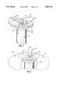
- FIG. 4 is a perspective transverse cross-sectional view of the lower stage rocket motor shown in FIG. 1, further illustrating a grid of conical explosive charges secured to the rocket motor case.
- FIG. 5 is a perspective view illustrating an alternative embodiment in which two lines lead to through-bulkhead-initiators for use in normal ignition and two additional lines lead to separate through-bulkhead-initiators for use in destruction ignition of a motor igniter.
- FIG. 6 is a longitudinal cross-section taken along line 6--6 of FIG. 5.
- FIG. 7 is a schematic diagram illustrating a firing unit having a single pyrotechnic signal output which is replicated by an ordnance T to allow propagation of a motor ignition signal along a first line and delayed propagation of a charge explosion signal along a second line.
- FIG. 8 is a schematic diagram illustrating a firing unit having a first electronic signal output to allow propagation of a motor ignition signal along a first line and having an incorporated electronic delay unit and a second electronic signal output to allow delayed propagation of a charge explosion signal along a second line.
- FIG. 9 is a flowchart illustrating possible steps in a method for shattering a launch vehicle according to the present invention.
- the present invention relates to a system for shattering a launch vehicle such as the vehicle indicated generally at 10.
- a launch vehicle such as the vehicle indicated generally at 10.
- the launch vehicle used with the present invention may be a ballistic missile, an air-to-air missile, a rocket, a torpedo, a reusable aerospace vehicle, or any other vehicle capable of being launched into flight in the air, in space, or under the sea.
- the launch vehicle 10 is propelled solely by several solid fuel rocket motors 12.
- Other launch vehicles used with the present invention may be configured with other propulsive means such as liquid fuel or hybrid rocket motors (not shown), provided that they also include at least one solid fuel rocket motor.
- Each solid fuel rocket motor 12 includes a solid fuel propellant 14 disposed about a combustion chamber 16 within a rocket motor case 18. The propellant 14 and the case 18 are formed according to methods well-known in the art.
- each rocket motor 12 also includes at least one motor igniter 20 adjacent the propellant 14.
- the motor igniter 20 is capable of igniting the propellant 14 during flight of the launch vehicle 10.
- At least one ignition line 22 leads to a through-bulkhead-initiator 24 positioned adjacent the motor igniter 20 and capable of actuating the igniter 20.
- At least one redundant ignition line 26 leads to a corresponding redundant through-bulkhead-initiator 28 (also shown in phantom) adjacent the motor igniter 20.
- the lines 22, 26 and the initiators 24, 28 form part of the normal motor ignition train.
- the lines 22, 26 and the initiators 24, 28 also form part of the destruction ignition train unless separate lines and initiators are provided as described hereafter.
- FIG. 1 shows an upper stage rocket motor 32 and a lower stage rocket motor 34 configured differently with explosive charges 36 and 38, respectively.
- the upper stage explosive charge 36 includes a conventional destruction vent charge in the form of one or more linear shaped charge assemblies 40 as shown in FIG. 3.
- the lower stage explosive charge 38 shown best in FIG. 4, includes a grid of explosive charges.
- a grid of conical charges 38 is illustrated, but those of skill will appreciate that a variety of other explosive shapes may also be employed according to the teachings herein.
- the charges 38 may be configured for either simultaneous or sequential actuation.
- Suitable explosive charges 30 include aluminum- or copper-sheathed charges, including linear or other shaped charges, containing a suitable high explosive material (e.g., HMX or RDX) sized and configured to reliably shatter the pressurized case 18.
- the launch vehicle 10 includes at least one controller 42.
- the controller 42 may comprise a conventional command destruct receiver connected to an antenna for receiving a destruct order from a remote radio transmitter (not shown).
- the controller 42 preferably comprises a subunit capable of decrypting and validating the destruct order.
- the controller 42 is capable of generating a destruct signal in response to a valid order received at the launch vehicle 10 from an external source such as an authority (not shown) at the location from which the vehicle 10 was launched.
- the destruct signal is transmitted to at least one firing unit 44, and preferably to a firing unit 44 on each of the rocket motors 12. Unless otherwise expressly indicated herein, it is understood that the firing units 44 (FIG. 3), 45 (FIG. 8), and 46 (FIG. 3) function in the same manner as one another, and that a reference to a particular firing unit also applies to the other firing units described herein.
- the controller 42 or the firing unit 44 may generate the destruct signal solely in response to alarms raised by diagnostic or control systems on board the vehicle 10.
- a diagnostic subunit of a firing unit 44 on each of the rocket motors 12 preferably generates a destruct signal in response to undesired separation of one or more rocket motors 12 from the vehicle 10.
- Appropriate controllers and diagnostic systems are well known and understood in the art.
- each firing unit 44 is capable of receiving the destruct signal from the controller 42 or of generating the destruct signal in response to firing unit diagnostics, and of generating in response to the destruct signal a motor ignition signal and a charge explosion signal.
- each rocket motor 12 is preferably also configured with a redundant firing unit 46 which is likewise capable of generating a motor ignition signal and a charge explosion signal in response to a destruct signal.
- Each firing unit 44, 46 is connected to at least one explosive charge 30 by a portion 48, 50, respectively, of a charge explosion signal propagator 52.
- the portions 48, 50 may include wires to carry electronic signals, pyrotechnic transmission lines to carry pyrotechnic signals, some other signal propagation means, or a mixture of signal propagation means.
- Each firing unit 44, 46 is also preferably connected to the motor initiator 20 (FIG. 5) by an ignition line 54, 56, respectively.
- the ignition lines 54, 56 are part of a motor ignition signal propagator 58.
- the term "signal" comprises both electronic signals and pyrotechnic signals unless otherwise indicated.
- an electronic impulse traveling along a wire is a signal.
- a region of ignition traveling along a fuse, an ordnance delay, or another type of pyrotechnic transmission line is likewise a signal.
- Other types of signals which require no transmission medium including optical signals, microwave signals, and radio frequency signals, also lie within the scope of the term “signal” as used herein. Accordingly, although particular embodiments of the signal propagators 52 and 58 may employ pyrotechnic transmission lines and wires, those of skill in the art will appreciate that other embodiments of the propagators 52, 58 also lie within the scope of the present invention.
- the motor ignition signal propagator 58 has a motor ignition signal input 60 and a motor ignition signal output 62.
- input and “output” each include one or more spatially separated points near the beginning and ending, respectively, of a signal transmission path.
- the motor ignition signal input 60 is connected in signal communication with at least one firing unit such as the firing unit 44 for receiving the motor ignition signal from the firing unit 44.
- the motor ignition signal propagator 58 is capable of propagation of the motor ignition signal such that the motor ignition signal arrives at the motor ignition signal output 62 a motor ignition signal propagation time T ignition after the destruct signal reaches the firing unit 44.
- the motor ignition signal output 62 is configured in communication with additional through-bulkhead-initiators 64, 66 to cause ignition of the previously unignited propellant 14 in the solid fuel rocket motor 12 (FIG. 1) in response to the arrival of the motor ignition signal.
- the present invention intentionally initiates ignition of at least one upper stage 32. Indeed, it is preferred that every unignited upper stage and every other unignited solid fuel stage of the launch vehicle 10 be ignited.
- the motor ignition signal output 62 may be connected to the normal motor initiators 24, 28.
- the system include at least one destruction motor initiator 64, and most preferably also include a redundant destruction motor initiator 66, as illustrated in FIG. 5.
- the destruction motor initiators 64, 66 are secured to the rocket motor 12 (FIG. 1) in signal communication with the motor ignition signal output 62 adjacent the motor igniter 20 as part of a destruction ignition train.
- either or both destruction motor initiators 64, 66 are capable of initiating ignition of the propellant 14 in response to the motor ignition signal if the launch vehicle 10 (FIG. 1) strays substantially from the desired flight path.
- Using separate destruction motor initiators 64, 66 is preferred to preserve the integrity and reliability of the normal motor ignition train.
- the charge explosion signal propagator 52 has a charge explosion signal input 68 and a charge explosion signal output 70.
- the charge explosion signal input 68 is connected in signal communication with at least one of the firing units 44, 46 on the rocket motor 12 for receiving the charge explosion signal.
- the charge explosion signal propagator 52 is capable of propagation of the charge explosion signal such that the charge explosion signal arrives at the charge explosion signal output 70 a charge explosion signal propagation time T explosion after the destruct signal reaches the firing unit 44.
- the charge explosion signal output 70 is configured in conventional manner to cause actuation of the explosive charge 30 in response to the arrival of the charge explosion signal.
- the charge explosion signal propagation time T explosion is greater than the motor ignition signal propagation time T ignition by a pressurization time T pressurization which is sufficient to allow ignition of the propellant 14 and consequent pressurization of the combustion chamber 16 in response to the motor ignition signal before actuation of the explosive charge 30 in response to the charge explosion signal.
- a pressurization time T pressurization in the range from about 100 milliseconds to about 1000 milliseconds is suitable, and a pressurization time T pressurization in the range from about 200 milliseconds to about 400 milliseconds is preferred.
- CASTOR is a trademark of Thiokol Corporation.
- Pressurization of the combustion chamber 16 exerts forces on the rocket motor case 18 which act in combination with the subsequent force from explosion of the charge 30 to shatter both the case 18 and the propellant 14. These combined forces are particularly effective on composite rocket motor cases 18, but the present invention is also suitable for use with rocket motor cases 18 formed of steel or other materials.
- FIG. 7 illustrates an existing technology firing unit 44 adapted for use according to the teachings herein.
- the firing unit 44 is configured to receive a destruct signal from a controller 42 (FIG. 3) along a wire 72.
- the firing unit 44 is in signal communication with a pyrotechnic transmission line 74. In a conventional destruction system, the line 74 would lead only to a motor igniter 20 (FIG. 2).
- the line 74 leads to a fork or "T" 76.
- the T 76 may be a conventional ordnance T.
- the T 76 transmits a pyrotechnic signal from the line 74 as two signals along two lines 78, 80.
- the line 78 leads to a motor igniter 20.
- the line 54 or the line 56 in FIG. 5 may be embodied as the line 78.
- the lines 78, 54, and 56 each carry a motor ignition signal and form part of the motor ignition signal propagator 58 described herein.
- the line 80 leads up to, and then away from, a delay unit 82.
- the line 48 or the line 50 in FIG. 3 may be embodied as the line 80.
- the lines 48, 50, and 80 each carry a charge explosion signal and form part of the charge explosion signal propagator 52.
- the delay unit 82 which is also part of the explosion propagator 52, may in general include mechanical, electronic, and/or pyrotechnical components. As the explosion propagator 52 in the embodiment shown in FIG. 7 carries a pyrotechnic charge explosion signal, the delay unit 82 in that embodiment is preferably a conventional ordnance delay.
- the embodiment of the explosion propagator 52 in FIG. 8 carries an electronic charge explosion signal.
- a delay unit 84 comprising conventional electronic delay unit circuitry is preferably employed.
- the electronic delay unit 84 is preferably housed in the same housing 86 as the circuitry of a firing unit 45 which provides two separate electronic outputs 88, 90.
- the output 88 provides an electronic motor ignition signal to an ignition wire 92.
- the line 54 or the line 56 in FIG. 5 may be embodied as the ignition wire 92.
- the output 90 provides an electronic charge explosion signal, after a suitable pressurization time delay T pressurization caused by the delay unit 84, to a charge explosion wire 94.
- the line 48 or the line 50 in FIG. 3 may be embodied as the charge explosion wire 94.
- the present invention also provides a method for destroying a launch vehicle.
- the launch vehicle includes at least one unignited solid fuel rocket motor.
- the solid fuel rocket motor may be a second or later stage of a multi-stage rocket motor, or it may be a single stage solid fuel rocket motor secured to a launch vehicle that is also propelled by means other than solid fuel rocket motors.
- Each rocket motor includes a solid fuel propellant disposed about a combustion chamber within a rocket motor case.
- Each rocket motor also includes at least one explosive charge,positioned adjacent the rocket motor case.
- a destruct signal is received at each rocket motor as indicated at 100 in FIG. 9. It is understood that the destruct signal may be generated by a diagnostic subunit secured to the rocket motor in question. In response, the rocket motor stages may be separated, as indicated .at 102. Alternatively, the separation of stages 102 may be skipped. For each rocket motor, steps are then taken in response to the destruct signal.
- rocket motors are indicated in FIG. 9 by three generally parallel subsequences of events beginning at 104, 106, and 108, respectively, those of skill in the art will understand that the present invention is useful for shattering a launch vehicle having one or more solid fuel rocket motors. Also, vehicles having multiple rocket motors may include motors arranged either in parallel or as sequential stages.
- the previously unignited propellant of each rocket motor is ignited.
- the ignitions 104, 106, 108 are preferably substantially simultaneous, they may also be separated in time. Igniting causes the subsequent pressurization of the combustion chamber of each rocket motor by placing within the chamber combustion products of the ignited propellant.
- a pressurization time T pressurization which depends on the particular rocket motor in question must elapse before a given pressurizing step 110, 112, 114 is complete. To allow adequate pressurization in a typical motor, this pressurization time T pressurization is in the range from about 100 milliseconds to about 1000 milliseconds, and is preferably in the range from about 200 milliseconds to about 400 milliseconds.
- the pressurization places the rocket motor propellant and the rocket motor case under tension, particularly if the case is formed of composites or similar materials.
- each rocket motor begins after sufficient pressurization as the explosive charge is exploded as indicated at 116, 188, and 120.
- the explosive charge is configured as described above to act in concert with the stresses created by combustion chamber pressurization to destroy the rocket motor by shattering it into many smaller pieces.
- the shattering step of the present method goes well beyond conventional steps that use explosives to merely pierce or make a cut in a rocket motor case. Even when they fracture the case, such conventional steps typically leave the propellant in one piece.
- the present method creates rocket motor case and propellant pieces that are substantially smaller than the original rocket motor.
- Each piece of the shattered motor has a weight that is preferably less than about one percent of the original weight (i.e., the combined weight of the original case and propellant immediately prior to the igniting step).
- the weight of each piece is most preferably less than about 0.1 percent of the original weight.
- the ignited motors pressurize the combustion chamber, which assists the explosive charge in shattering the rocket motor as described herein.
- igniting the fuel tends to decrease the propellant debris even after the explosion, because ignited solid fuel typically continues burning even if it does not form part of a combustion chamber.
- the propellant debris may burn and hence becomes smaller even as it falls.
- smaller pieces of debris have a greater aerodynamic drag-to-mass ratio and thus do not generally travel as far along the original ballistic trajectory as larger pieces.
- the present invention provides a system and method for shattering a solid fuel rocket motor into many smaller pieces by subjecting the rocket motor case and propellant to the combined forces of motor pressurization and charge explosion.
- the rocket motor is first stressed from inside by pressurization of the combustion chamber.
- the rocket motor case is then subjected to explosive forces from at least one explosive charge.
- the motor shatters into many smaller pieces, thereby greatly reducing the risk to populated areas.
- the forces acting on the motor, and those created by the flying pieces of the shattered motor also tend to break the entire launch vehicle into smaller pieces.
Abstract
Description
Claims (23)
Priority Applications (5)
| Application Number | Priority Date | Filing Date | Title |
|---|---|---|---|
| US08/322,917 US5507231A (en) | 1994-10-13 | 1994-10-13 | Solid fuel launch vehicle destruction system and method |
| EP95938143A EP0784781B1 (en) | 1994-10-13 | 1995-10-12 | Solid fuel launch vehicle destruction system and method |
| PCT/US1995/012682 WO1996012155A1 (en) | 1994-10-13 | 1995-10-12 | Solid fuel launch vehicle destruction system and method |
| ES95938143T ES2140720T3 (en) | 1994-10-13 | 1995-10-12 | SYSTEM AND PROCEDURE FOR THE DESTRUCTION OF A FUEL-OPERATED LAUNCH VEHICLE. |
| JP51327596A JP3676810B2 (en) | 1994-10-13 | 1995-10-12 | Solid fuel launch vehicle destruction system and method |
Applications Claiming Priority (1)
| Application Number | Priority Date | Filing Date | Title |
|---|---|---|---|
| US08/322,917 US5507231A (en) | 1994-10-13 | 1994-10-13 | Solid fuel launch vehicle destruction system and method |
Publications (1)
| Publication Number | Publication Date |
|---|---|
| US5507231A true US5507231A (en) | 1996-04-16 |
Family
ID=23257010
Family Applications (1)
| Application Number | Title | Priority Date | Filing Date |
|---|---|---|---|
| US08/322,917 Expired - Lifetime US5507231A (en) | 1994-10-13 | 1994-10-13 | Solid fuel launch vehicle destruction system and method |
Country Status (5)
| Country | Link |
|---|---|
| US (1) | US5507231A (en) |
| EP (1) | EP0784781B1 (en) |
| JP (1) | JP3676810B2 (en) |
| ES (1) | ES2140720T3 (en) |
| WO (1) | WO1996012155A1 (en) |
Cited By (14)
| Publication number | Priority date | Publication date | Assignee | Title |
|---|---|---|---|---|
| WO1999017988A2 (en) * | 1997-10-03 | 1999-04-15 | Lockheed Martin Corporation | Mass producible launch system |
| US6079202A (en) * | 1998-04-17 | 2000-06-27 | Cesaroni; Anthony J. | Reloadable/modular solid propellant rocket motor |
| FR2791425A1 (en) * | 1999-03-24 | 2000-09-29 | Giat Ind Sa | Device for deconfining wall of rocket, missile, etc., comprises charges with explosive load, initiated by detonation relay linked to control unit |
| WO2002008684A1 (en) * | 2000-07-26 | 2002-01-31 | Giat Industries | Device for neutralising a payload |
| EP1310425A1 (en) * | 2001-11-08 | 2003-05-14 | Gascom GmbH, Kompressortechnik | Self-destruction mechanism for aircraft |
| US20070095239A1 (en) * | 2005-10-28 | 2007-05-03 | Skinner Anthony T | Device for venting a container housing an energetic material and method of using same |
| US20120240808A1 (en) * | 2009-07-17 | 2012-09-27 | Tda Armements Sas | Ammunition Comprising Means for Neutralizing Its Explosive Charge |
| US20160052649A1 (en) * | 2014-08-21 | 2016-02-25 | Ventions, Llc | Fail-safe command destruct system |
| US20170122259A1 (en) * | 2015-11-04 | 2017-05-04 | Orbital Atk, Inc. | Solid rocket motors including flight termination systems, and related multi-stage solid rocket motor assemblies and methods |
| US10023329B1 (en) * | 2017-03-04 | 2018-07-17 | Othniel Mbamalu | Space vehicle system |
| RU2724096C1 (en) * | 2019-08-05 | 2020-06-19 | Акционерное общество "Корпорация "Московский институт теплотехники" (АО "Корпорация "МИТ") | Start solid propellant accelerator of carrier rocket and method of assembly thereof |
| CN114837851A (en) * | 2022-04-01 | 2022-08-02 | 湖北三江航天红峰控制有限公司 | Rocket safe ignition control circuit and method based on relay |
| US11499505B2 (en) * | 2020-06-09 | 2022-11-15 | Raytheon Company | Multi-pulse rocket motor with flight termination destruct charge |
| US11732676B1 (en) | 2022-04-01 | 2023-08-22 | Raytheon Company | Rocket motor with embedded burnable cutting explosive energetic material |
Families Citing this family (2)
| Publication number | Priority date | Publication date | Assignee | Title |
|---|---|---|---|---|
| JP2013068117A (en) * | 2011-09-21 | 2013-04-18 | Ihi Aerospace Co Ltd | Solid rocket safety device |
| CN112762762B (en) * | 2020-12-23 | 2022-10-04 | 中国船舶重工集团有限公司第七一0研究所 | Autonomous type firing line shearing device |
Citations (29)
| Publication number | Priority date | Publication date | Assignee | Title |
|---|---|---|---|---|
| US3205821A (en) * | 1962-10-18 | 1965-09-14 | France Etat | Projectile propulsive system with pressure-actuable arming means |
| US3229638A (en) * | 1964-07-31 | 1966-01-18 | Lionel L Woolston | Air-launch environmental safing device |
| US3487644A (en) * | 1968-04-26 | 1970-01-06 | Us Navy | Device to render a rocket motor non-propulsive by rupturing the motor case |
| US3726215A (en) * | 1971-07-16 | 1973-04-10 | Us Navy | Explosive destruct device |
| US4007688A (en) * | 1976-02-23 | 1977-02-15 | The United States Of America As Represented By The Secretary Of The Navy | Timed missile flight termination system |
| US4057442A (en) * | 1976-03-29 | 1977-11-08 | Thiokol Corporation | Method of disposal of pyrotechnic compositions |
| US4361450A (en) * | 1975-06-02 | 1982-11-30 | Thiokol Corporation | Plastic bonded explosive compositions |
| US4404911A (en) * | 1981-11-05 | 1983-09-20 | Thiokol Corporation | Self-sparging inertia armed nose fuze |
| US4557198A (en) * | 1982-03-04 | 1985-12-10 | The Secretary Of State For Defence In Her Britannic Majesty's Government Of The United Kingdom Of Great Britain And Northern Ireland | Safety devices for carrier shells |
| US4649824A (en) * | 1985-06-27 | 1987-03-17 | The United States Of America As Represented By The Secretary Of The Navy | Apparatus for aerospace vehicle separation events using a linear shaped charge |
| US4660472A (en) * | 1985-10-07 | 1987-04-28 | Morton Thiokol Inc. | Optical through bulkhead initiator and safe-arm device |
| US4699066A (en) * | 1985-10-25 | 1987-10-13 | Morton Thiokol Inc. | Linear explosive separation system |
| US4716830A (en) * | 1985-07-29 | 1988-01-05 | Morton Thiokol, Inc. | Inertia safety and arming device |
| US4766726A (en) * | 1985-12-27 | 1988-08-30 | Morton Thiokol, Inc. | Segmented case rocket motor |
| US4793888A (en) * | 1986-07-11 | 1988-12-27 | Morton Thiokol, Inc. | System for underwater and cold temperature bonding |
| US4793887A (en) * | 1986-07-11 | 1988-12-27 | Morton Thiokol, Inc. | Underwater bonding of surface-conforming material |
| US4829765A (en) * | 1985-12-27 | 1989-05-16 | Morton Thiokol, Inc. | Pulsed rocket motor |
| US4901642A (en) * | 1988-10-27 | 1990-02-20 | Morton Thiokol, Inc. | Consumable wafer igniter |
| US5044154A (en) * | 1989-11-27 | 1991-09-03 | Thiokol Corporation | Safety mechanism for rendering a rocket motor non-propulsive |
| US5060470A (en) * | 1990-05-22 | 1991-10-29 | Thiokol Corporation | Gas generator ventable at a high temperature for hazard reduction |
| US5070691A (en) * | 1988-08-03 | 1991-12-10 | Thiokol Corporation | Solid propellant canister loaded multiple pulsed or staged rocket |
| US5117758A (en) * | 1991-09-25 | 1992-06-02 | The United States Of America As Represented By The Secretary Of The Navy | Booster rocket range safety system |
| US5127223A (en) * | 1986-09-18 | 1992-07-07 | Thiokol Corporation | Solid rocket motor propellants with reticulated structures embedded therein and method of manufacture thereof |
| US5150654A (en) * | 1987-10-15 | 1992-09-29 | Thiokol Corporation | Spherical igniter for full head-end web rocket motors |
| US5166468A (en) * | 1991-04-05 | 1992-11-24 | Thiokol Corporation | Thermocouple-triggered igniter |
| US5206989A (en) * | 1988-08-03 | 1993-05-04 | Thiokol Corporation | Method of making solid propellant canister loaded rocket motor |
| US5228285A (en) * | 1992-03-02 | 1993-07-20 | Thiokol Corporation | Solid propellant rocket motor case for insensitive munitions requirements |
| US5280706A (en) * | 1992-06-25 | 1994-01-25 | Thiokol Corporation | Composite/metal hybrid rocket motor case and methods for manufacturing |
| US5337672A (en) * | 1991-11-29 | 1994-08-16 | Thomson-Brandt Armements | Locking device for a casing containing pyrotechnic materials |
Family Cites Families (4)
| Publication number | Priority date | Publication date | Assignee | Title |
|---|---|---|---|---|
| US3572249A (en) * | 1968-09-11 | 1971-03-23 | Us Air Force | High efficiency rocket munition |
| US3995549A (en) * | 1975-03-17 | 1976-12-07 | The United States Of America As Represented By The Secretary Of The Navy | Rocket/missile motor explosive insert detonator |
| FR2385075A1 (en) * | 1977-03-23 | 1978-10-20 | Haut Rhin Manufacture Machines | Charge scattering rocket propulsion system - has igniter charge to actuate excess of propulsive charge to destroy remaining parts |
| US4459915A (en) * | 1982-10-18 | 1984-07-17 | General Dynamics Corporation/Convair Div. | Combined rocket motor warhead |
-
1994
- 1994-10-13 US US08/322,917 patent/US5507231A/en not_active Expired - Lifetime
-
1995
- 1995-10-12 WO PCT/US1995/012682 patent/WO1996012155A1/en active IP Right Grant
- 1995-10-12 ES ES95938143T patent/ES2140720T3/en not_active Expired - Lifetime
- 1995-10-12 EP EP95938143A patent/EP0784781B1/en not_active Expired - Lifetime
- 1995-10-12 JP JP51327596A patent/JP3676810B2/en not_active Expired - Fee Related
Patent Citations (29)
| Publication number | Priority date | Publication date | Assignee | Title |
|---|---|---|---|---|
| US3205821A (en) * | 1962-10-18 | 1965-09-14 | France Etat | Projectile propulsive system with pressure-actuable arming means |
| US3229638A (en) * | 1964-07-31 | 1966-01-18 | Lionel L Woolston | Air-launch environmental safing device |
| US3487644A (en) * | 1968-04-26 | 1970-01-06 | Us Navy | Device to render a rocket motor non-propulsive by rupturing the motor case |
| US3726215A (en) * | 1971-07-16 | 1973-04-10 | Us Navy | Explosive destruct device |
| US4361450A (en) * | 1975-06-02 | 1982-11-30 | Thiokol Corporation | Plastic bonded explosive compositions |
| US4007688A (en) * | 1976-02-23 | 1977-02-15 | The United States Of America As Represented By The Secretary Of The Navy | Timed missile flight termination system |
| US4057442A (en) * | 1976-03-29 | 1977-11-08 | Thiokol Corporation | Method of disposal of pyrotechnic compositions |
| US4404911A (en) * | 1981-11-05 | 1983-09-20 | Thiokol Corporation | Self-sparging inertia armed nose fuze |
| US4557198A (en) * | 1982-03-04 | 1985-12-10 | The Secretary Of State For Defence In Her Britannic Majesty's Government Of The United Kingdom Of Great Britain And Northern Ireland | Safety devices for carrier shells |
| US4649824A (en) * | 1985-06-27 | 1987-03-17 | The United States Of America As Represented By The Secretary Of The Navy | Apparatus for aerospace vehicle separation events using a linear shaped charge |
| US4716830A (en) * | 1985-07-29 | 1988-01-05 | Morton Thiokol, Inc. | Inertia safety and arming device |
| US4660472A (en) * | 1985-10-07 | 1987-04-28 | Morton Thiokol Inc. | Optical through bulkhead initiator and safe-arm device |
| US4699066A (en) * | 1985-10-25 | 1987-10-13 | Morton Thiokol Inc. | Linear explosive separation system |
| US4829765A (en) * | 1985-12-27 | 1989-05-16 | Morton Thiokol, Inc. | Pulsed rocket motor |
| US4766726A (en) * | 1985-12-27 | 1988-08-30 | Morton Thiokol, Inc. | Segmented case rocket motor |
| US4793888A (en) * | 1986-07-11 | 1988-12-27 | Morton Thiokol, Inc. | System for underwater and cold temperature bonding |
| US4793887A (en) * | 1986-07-11 | 1988-12-27 | Morton Thiokol, Inc. | Underwater bonding of surface-conforming material |
| US5127223A (en) * | 1986-09-18 | 1992-07-07 | Thiokol Corporation | Solid rocket motor propellants with reticulated structures embedded therein and method of manufacture thereof |
| US5150654A (en) * | 1987-10-15 | 1992-09-29 | Thiokol Corporation | Spherical igniter for full head-end web rocket motors |
| US5206989A (en) * | 1988-08-03 | 1993-05-04 | Thiokol Corporation | Method of making solid propellant canister loaded rocket motor |
| US5070691A (en) * | 1988-08-03 | 1991-12-10 | Thiokol Corporation | Solid propellant canister loaded multiple pulsed or staged rocket |
| US4901642A (en) * | 1988-10-27 | 1990-02-20 | Morton Thiokol, Inc. | Consumable wafer igniter |
| US5044154A (en) * | 1989-11-27 | 1991-09-03 | Thiokol Corporation | Safety mechanism for rendering a rocket motor non-propulsive |
| US5060470A (en) * | 1990-05-22 | 1991-10-29 | Thiokol Corporation | Gas generator ventable at a high temperature for hazard reduction |
| US5166468A (en) * | 1991-04-05 | 1992-11-24 | Thiokol Corporation | Thermocouple-triggered igniter |
| US5117758A (en) * | 1991-09-25 | 1992-06-02 | The United States Of America As Represented By The Secretary Of The Navy | Booster rocket range safety system |
| US5337672A (en) * | 1991-11-29 | 1994-08-16 | Thomson-Brandt Armements | Locking device for a casing containing pyrotechnic materials |
| US5228285A (en) * | 1992-03-02 | 1993-07-20 | Thiokol Corporation | Solid propellant rocket motor case for insensitive munitions requirements |
| US5280706A (en) * | 1992-06-25 | 1994-01-25 | Thiokol Corporation | Composite/metal hybrid rocket motor case and methods for manufacturing |
Cited By (22)
| Publication number | Priority date | Publication date | Assignee | Title |
|---|---|---|---|---|
| WO1999017988A2 (en) * | 1997-10-03 | 1999-04-15 | Lockheed Martin Corporation | Mass producible launch system |
| WO1999017988A3 (en) * | 1997-10-03 | 1999-06-17 | Lockheed Corp | Mass producible launch system |
| US6036144A (en) * | 1997-10-03 | 2000-03-14 | Lockheed Martin Corporation | Mass producible launch system |
| US6079202A (en) * | 1998-04-17 | 2000-06-27 | Cesaroni; Anthony J. | Reloadable/modular solid propellant rocket motor |
| FR2791425A1 (en) * | 1999-03-24 | 2000-09-29 | Giat Ind Sa | Device for deconfining wall of rocket, missile, etc., comprises charges with explosive load, initiated by detonation relay linked to control unit |
| US6718883B2 (en) | 2000-01-26 | 2004-04-13 | Giat Industries | Device for neutralizing a payload |
| WO2002008684A1 (en) * | 2000-07-26 | 2002-01-31 | Giat Industries | Device for neutralising a payload |
| FR2812384A1 (en) * | 2000-07-26 | 2002-02-01 | Giat Ind Sa | DEVICE FOR NEUTRALIZING A PAYLOAD |
| EP1310425A1 (en) * | 2001-11-08 | 2003-05-14 | Gascom GmbH, Kompressortechnik | Self-destruction mechanism for aircraft |
| US7373885B2 (en) * | 2005-10-28 | 2008-05-20 | Lockheed Martin Corporation | Device for venting a container housing an energetic material and method of using same |
| US20070095239A1 (en) * | 2005-10-28 | 2007-05-03 | Skinner Anthony T | Device for venting a container housing an energetic material and method of using same |
| US20120240808A1 (en) * | 2009-07-17 | 2012-09-27 | Tda Armements Sas | Ammunition Comprising Means for Neutralizing Its Explosive Charge |
| US8584588B2 (en) * | 2009-07-17 | 2013-11-19 | Tda Armements Sas | Ammunition comprising means for neutralizing its explosive charge |
| US20160052649A1 (en) * | 2014-08-21 | 2016-02-25 | Ventions, Llc | Fail-safe command destruct system |
| US20170122259A1 (en) * | 2015-11-04 | 2017-05-04 | Orbital Atk, Inc. | Solid rocket motors including flight termination systems, and related multi-stage solid rocket motor assemblies and methods |
| US10781773B2 (en) * | 2015-11-04 | 2020-09-22 | Northrop Grumman Innovation Systems, Inc. | Solid rocket motors including flight termination systems, and related multi-stage solid rocket motor assemblies and methods |
| US10023329B1 (en) * | 2017-03-04 | 2018-07-17 | Othniel Mbamalu | Space vehicle system |
| RU2724096C1 (en) * | 2019-08-05 | 2020-06-19 | Акционерное общество "Корпорация "Московский институт теплотехники" (АО "Корпорация "МИТ") | Start solid propellant accelerator of carrier rocket and method of assembly thereof |
| US11499505B2 (en) * | 2020-06-09 | 2022-11-15 | Raytheon Company | Multi-pulse rocket motor with flight termination destruct charge |
| CN114837851A (en) * | 2022-04-01 | 2022-08-02 | 湖北三江航天红峰控制有限公司 | Rocket safe ignition control circuit and method based on relay |
| US11732676B1 (en) | 2022-04-01 | 2023-08-22 | Raytheon Company | Rocket motor with embedded burnable cutting explosive energetic material |
| WO2023192059A1 (en) * | 2022-04-01 | 2023-10-05 | Raytheon Company | Rocket motor with embedded burnable cutting explosive energetic material |
Also Published As
| Publication number | Publication date |
|---|---|
| EP0784781A1 (en) | 1997-07-23 |
| JPH10511174A (en) | 1998-10-27 |
| EP0784781A4 (en) | 1998-01-07 |
| ES2140720T3 (en) | 2000-03-01 |
| EP0784781B1 (en) | 1999-12-22 |
| JP3676810B2 (en) | 2005-07-27 |
| WO1996012155A1 (en) | 1996-04-25 |
Similar Documents
| Publication | Publication Date | Title |
|---|---|---|
| US5507231A (en) | Solid fuel launch vehicle destruction system and method | |
| US6105505A (en) | Hard target incendiary projectile | |
| US5698814A (en) | Hard target penetrator with multi-segmenting casing cutter | |
| US7762195B2 (en) | Slow cook off rocket igniter | |
| EP1342981B9 (en) | Gun-launched rocket | |
| US6619029B2 (en) | Rocket motors with insensitive munitions systems | |
| JPS60252146A (en) | Safety system of rocket motor operated by temperature | |
| CA1235582A (en) | Solid rocket motor with dual interrrupted thrust | |
| US6230629B1 (en) | Rapid ignition infrared decoy for anti-ship missile | |
| JP4619813B2 (en) | Two-stage thrust rocket motor | |
| US7814835B2 (en) | Propulsion enhancement arrangement for rocket | |
| US6283032B1 (en) | Projectile with controlled decomposition and integrated charge in the area of the effective mass | |
| JP4619814B2 (en) | Two-stage thrust rocket motor | |
| US3273337A (en) | Linear explosive type igniter train for rocket motor | |
| Cooper | Electro-explosive devices | |
| US6615736B2 (en) | Priming device for an explosive charge and shaped charge incorporating such a priming device | |
| EP1440233B1 (en) | Rocket motors with insensitive munitions systems | |
| JP2002115998A (en) | Propeller of projectile and side jet unit | |
| Hubbard et al. | Explosiveness and shock-induced deflagration studies of large confined explosive charges | |
| JPH03160300A (en) | Ram jet shell | |
| Duce et al. | Flight termination system for destruction of unpressurized solid propellant motors | |
| JPH0850000A (en) | Anti-armor airframe | |
| Roglic et al. | Warheads of Surface-To-Air Guided Missiles | |
| JPH11142095A (en) | Airframe launching device | |
| KR20000015047U (en) | Explosion shock mitigation device of explosion bolt |
Legal Events
| Date | Code | Title | Description |
|---|---|---|---|
| AS | Assignment |
Owner name: THIOKOL CORPORATION, UTAH Free format text: ASSIGNMENT OF ASSIGNORS INTEREST;ASSIGNORS:MOORE, STEVEN E.;DUCE, F. LYNN;REEL/FRAME:007267/0265 Effective date: 19941202 |
|
| STCF | Information on status: patent grant |
Free format text: PATENTED CASE |
|
| FPAY | Fee payment |
Year of fee payment: 4 |
|
| AS | Assignment |
Owner name: CORDANT TECHNOLOGIES, INC., UTAH Free format text: CHANGE OF NAME;ASSIGNOR:THIOKOL CORPORATION;REEL/FRAME:011712/0322 Effective date: 19980423 |
|
| AS | Assignment |
Owner name: THE CHASE MANHATTAN BANK, NEW YORK Free format text: PATENT SECURITY AGREEMENT;ASSIGNOR:ALLIANT TECHSYSTEMS INC.;REEL/FRAME:011821/0001 Effective date: 20010420 |
|
| AS | Assignment |
Owner name: ALLIANT TECHSYSTEMS INC., MINNESOTA Free format text: ASSIGNMENT OF ASSIGNORS INTEREST;ASSIGNOR:THIOKOL PROPULSION CORP.;REEL/FRAME:012343/0001 Effective date: 20010907 Owner name: THIOKOL PROPULSION CORP., UTAH Free format text: CHANGE OF NAME;ASSIGNOR:CORDANT TECHNOLOGIES INC.;REEL/FRAME:012391/0001 Effective date: 20010420 |
|
| FPAY | Fee payment |
Year of fee payment: 8 |
|
| FEPP | Fee payment procedure |
Free format text: PAYOR NUMBER ASSIGNED (ORIGINAL EVENT CODE: ASPN); ENTITY STATUS OF PATENT OWNER: LARGE ENTITY |
|
| AS | Assignment |
Owner name: ALLIANT TECHSYSTEMS INC., MINNESOTA Free format text: RELEASE OF SECURITY AGREEMENT;ASSIGNOR:JPMORGAN CHASE BANK (FORMERLY KNOWN AS THE CHASE MANHATTAN BANK);REEL/FRAME:015201/0095 Effective date: 20040331 |
|
| AS | Assignment |
Owner name: BANK OF AMERICA, N.A., NORTH CAROLINA Free format text: SECURITY INTEREST;ASSIGNORS:ALLIANT TECHSYSTEMS INC.;ALLANT AMMUNITION AND POWDER COMPANY LLC;ALLIANT AMMUNITION SYSTEMS COMPANY LLC;AND OTHERS;REEL/FRAME:014692/0653 Effective date: 20040331 |
|
| FPAY | Fee payment |
Year of fee payment: 12 |
|
| REMI | Maintenance fee reminder mailed | ||
| AS | Assignment |
Owner name: BANK OF AMERICA, N.A., CALIFORNIA Free format text: SECURITY AGREEMENT;ASSIGNORS:ALLIANT TECHSYSTEMS INC.;AMMUNITION ACCESSORIES INC.;ATK COMMERCIAL AMMUNITION COMPANY INC.;AND OTHERS;REEL/FRAME:025321/0291 Effective date: 20101007 |
|
| AS | Assignment |
Owner name: BANK OF AMERICA, N.A., CALIFORNIA Free format text: SECURITY AGREEMENT;ASSIGNORS:ALLIANT TECHSYSTEMS INC.;CALIBER COMPANY;EAGLE INDUSTRIES UNLIMITED, INC.;AND OTHERS;REEL/FRAME:031731/0281 Effective date: 20131101 |
|
| AS | Assignment |
Owner name: ORBITAL ATK, INC., VIRGINIA Free format text: CHANGE OF NAME;ASSIGNOR:ALLIANT TECHSYSTEMS INC.;REEL/FRAME:035753/0373 Effective date: 20150209 |
|
| AS | Assignment |
Owner name: ALLIANT TECHSYSTEMS INC., VIRGINIA Free format text: RELEASE BY SECURED PARTY;ASSIGNOR:BANK OF AMERICA, N.A.;REEL/FRAME:036815/0330 Effective date: 20150929 Owner name: ORBITAL ATK, INC. (F/K/A ALLIANT TECHSYSTEMS INC.) Free format text: RELEASE BY SECURED PARTY;ASSIGNOR:BANK OF AMERICA, N.A.;REEL/FRAME:036815/0330 Effective date: 20150929 Owner name: COMPOSITE OPTICS, INC., CALIFORNIA Free format text: RELEASE BY SECURED PARTY;ASSIGNOR:BANK OF AMERICA, N.A.;REEL/FRAME:036815/0330 Effective date: 20150929 Owner name: FEDERAL CARTRIDGE CO., MINNESOTA Free format text: RELEASE BY SECURED PARTY;ASSIGNOR:BANK OF AMERICA, N.A.;REEL/FRAME:036815/0330 Effective date: 20150929 |
|
| AS | Assignment |
Owner name: ORBITAL ATK, INC. (F/K/A ALLIANT TECHSYSTEMS INC.), VIRGINIA Free format text: RELEASE BY SECURED PARTY;ASSIGNOR:BANK OF AMERICA, N.A.;REEL/FRAME:036816/0624 Effective date: 20150929 Owner name: ORBITAL ATK, INC. (F/K/A ALLIANT TECHSYSTEMS INC.) Free format text: RELEASE BY SECURED PARTY;ASSIGNOR:BANK OF AMERICA, N.A.;REEL/FRAME:036816/0624 Effective date: 20150929 Owner name: EAGLE INDUSTRIES UNLIMITED, INC., MISSOURI Free format text: RELEASE BY SECURED PARTY;ASSIGNOR:BANK OF AMERICA, N.A.;REEL/FRAME:036816/0624 Effective date: 20150929 Owner name: ALLIANT TECHSYSTEMS INC., VIRGINIA Free format text: RELEASE BY SECURED PARTY;ASSIGNOR:BANK OF AMERICA, N.A.;REEL/FRAME:036816/0624 Effective date: 20150929 Owner name: FEDERAL CARTRIDGE CO., MINNESOTA Free format text: RELEASE BY SECURED PARTY;ASSIGNOR:BANK OF AMERICA, N.A.;REEL/FRAME:036816/0624 Effective date: 20150929 Owner name: AMMUNITION ACCESSORIES, INC., ALABAMA Free format text: RELEASE BY SECURED PARTY;ASSIGNOR:BANK OF AMERICA, N.A.;REEL/FRAME:036816/0624 Effective date: 20150929 |
|
| FEPP | Fee payment procedure |
Free format text: PAYER NUMBER DE-ASSIGNED (ORIGINAL EVENT CODE: RMPN); ENTITY STATUS OF PATENT OWNER: LARGE ENTITY Free format text: PAYOR NUMBER ASSIGNED (ORIGINAL EVENT CODE: ASPN); ENTITY STATUS OF PATENT OWNER: LARGE ENTITY |
|
| AS | Assignment |
Owner name: NORTHROP GRUMMAN INNOVATION SYSTEMS, INC., MINNESOTA Free format text: CHANGE OF NAME;ASSIGNOR:ORBITAL ATK, INC.;REEL/FRAME:047400/0381 Effective date: 20180606 Owner name: NORTHROP GRUMMAN INNOVATION SYSTEMS, INC., MINNESO Free format text: CHANGE OF NAME;ASSIGNOR:ORBITAL ATK, INC.;REEL/FRAME:047400/0381 Effective date: 20180606 |