US5493859A - Engine with an adsorber - Google Patents
Engine with an adsorber Download PDFInfo
- Publication number
- US5493859A US5493859A US08/183,944 US18394494A US5493859A US 5493859 A US5493859 A US 5493859A US 18394494 A US18394494 A US 18394494A US 5493859 A US5493859 A US 5493859A
- Authority
- US
- United States
- Prior art keywords
- exhaust
- passage
- engine
- manifold
- exhaust gas
- Prior art date
- Legal status (The legal status is an assumption and is not a legal conclusion. Google has not performed a legal analysis and makes no representation as to the accuracy of the status listed.)
- Expired - Fee Related
Links
- 239000003054 catalyst Substances 0.000 claims abstract description 34
- 239000000463 material Substances 0.000 claims abstract description 25
- 239000011888 foil Substances 0.000 claims description 4
- 229910000510 noble metal Inorganic materials 0.000 claims description 3
- 239000011148 porous material Substances 0.000 claims description 2
- 239000011248 coating agent Substances 0.000 claims 2
- 238000000576 coating method Methods 0.000 claims 2
- 229910052751 metal Inorganic materials 0.000 claims 2
- 239000002184 metal Substances 0.000 claims 2
- 239000000446 fuel Substances 0.000 abstract description 6
- 230000005484 gravity Effects 0.000 abstract description 4
- 230000003213 activating effect Effects 0.000 abstract description 3
- 239000003463 adsorbent Substances 0.000 description 9
- 230000000694 effects Effects 0.000 description 6
- CURLTUGMZLYLDI-UHFFFAOYSA-N Carbon dioxide Chemical compound O=C=O CURLTUGMZLYLDI-UHFFFAOYSA-N 0.000 description 3
- KDLHZDBZIXYQEI-UHFFFAOYSA-N Palladium Chemical compound [Pd] KDLHZDBZIXYQEI-UHFFFAOYSA-N 0.000 description 3
- 239000000969 carrier Substances 0.000 description 3
- BASFCYQUMIYNBI-UHFFFAOYSA-N platinum Chemical compound [Pt] BASFCYQUMIYNBI-UHFFFAOYSA-N 0.000 description 3
- 229910021536 Zeolite Inorganic materials 0.000 description 2
- PNEYBMLMFCGWSK-UHFFFAOYSA-N aluminium oxide Inorganic materials [O-2].[O-2].[O-2].[Al+3].[Al+3] PNEYBMLMFCGWSK-UHFFFAOYSA-N 0.000 description 2
- 238000005219 brazing Methods 0.000 description 2
- 229910002092 carbon dioxide Inorganic materials 0.000 description 2
- 239000001569 carbon dioxide Substances 0.000 description 2
- 239000000919 ceramic Substances 0.000 description 2
- 239000011651 chromium Substances 0.000 description 2
- 238000010276 construction Methods 0.000 description 2
- HNPSIPDUKPIQMN-UHFFFAOYSA-N dioxosilane;oxo(oxoalumanyloxy)alumane Chemical compound O=[Si]=O.O=[Al]O[Al]=O HNPSIPDUKPIQMN-UHFFFAOYSA-N 0.000 description 2
- 238000002474 experimental method Methods 0.000 description 2
- 229930195733 hydrocarbon Natural products 0.000 description 2
- 150000002430 hydrocarbons Chemical class 0.000 description 2
- 238000000034 method Methods 0.000 description 2
- 238000012986 modification Methods 0.000 description 2
- 230000004048 modification Effects 0.000 description 2
- 239000002245 particle Substances 0.000 description 2
- 239000010457 zeolite Substances 0.000 description 2
- OKTJSMMVPCPJKN-UHFFFAOYSA-N Carbon Chemical compound [C] OKTJSMMVPCPJKN-UHFFFAOYSA-N 0.000 description 1
- VYZAMTAEIAYCRO-UHFFFAOYSA-N Chromium Chemical compound [Cr] VYZAMTAEIAYCRO-UHFFFAOYSA-N 0.000 description 1
- XEEYBQQBJWHFJM-UHFFFAOYSA-N Iron Chemical compound [Fe] XEEYBQQBJWHFJM-UHFFFAOYSA-N 0.000 description 1
- OAICVXFJPJFONN-UHFFFAOYSA-N Phosphorus Chemical compound [P] OAICVXFJPJFONN-UHFFFAOYSA-N 0.000 description 1
- NINIDFKCEFEMDL-UHFFFAOYSA-N Sulfur Chemical compound [S] NINIDFKCEFEMDL-UHFFFAOYSA-N 0.000 description 1
- 229910052782 aluminium Inorganic materials 0.000 description 1
- XAGFODPZIPBFFR-UHFFFAOYSA-N aluminium Chemical compound [Al] XAGFODPZIPBFFR-UHFFFAOYSA-N 0.000 description 1
- 238000005452 bending Methods 0.000 description 1
- 229910052799 carbon Inorganic materials 0.000 description 1
- 229910052804 chromium Inorganic materials 0.000 description 1
- 238000002485 combustion reaction Methods 0.000 description 1
- 230000003247 decreasing effect Effects 0.000 description 1
- 239000003344 environmental pollutant Substances 0.000 description 1
- 239000000203 mixture Substances 0.000 description 1
- 230000003647 oxidation Effects 0.000 description 1
- 238000007254 oxidation reaction Methods 0.000 description 1
- 229910052763 palladium Inorganic materials 0.000 description 1
- 239000008188 pellet Substances 0.000 description 1
- 229910052698 phosphorus Inorganic materials 0.000 description 1
- 239000011574 phosphorus Substances 0.000 description 1
- 229910052697 platinum Inorganic materials 0.000 description 1
- 231100000719 pollutant Toxicity 0.000 description 1
- 238000000746 purification Methods 0.000 description 1
- 229910052717 sulfur Inorganic materials 0.000 description 1
- 239000011593 sulfur Substances 0.000 description 1
- XLYOFNOQVPJJNP-UHFFFAOYSA-N water Substances O XLYOFNOQVPJJNP-UHFFFAOYSA-N 0.000 description 1
Images


Classifications
-
- B—PERFORMING OPERATIONS; TRANSPORTING
- B01—PHYSICAL OR CHEMICAL PROCESSES OR APPARATUS IN GENERAL
- B01D—SEPARATION
- B01D53/00—Separation of gases or vapours; Recovering vapours of volatile solvents from gases; Chemical or biological purification of waste gases, e.g. engine exhaust gases, smoke, fumes, flue gases, aerosols
- B01D53/34—Chemical or biological purification of waste gases
- B01D53/92—Chemical or biological purification of waste gases of engine exhaust gases
- B01D53/94—Chemical or biological purification of waste gases of engine exhaust gases by catalytic processes
- B01D53/9481—Catalyst preceded by an adsorption device without catalytic function for temporary storage of contaminants, e.g. during cold start
-
- B01J35/56—
-
- F—MECHANICAL ENGINEERING; LIGHTING; HEATING; WEAPONS; BLASTING
- F01—MACHINES OR ENGINES IN GENERAL; ENGINE PLANTS IN GENERAL; STEAM ENGINES
- F01N—GAS-FLOW SILENCERS OR EXHAUST APPARATUS FOR MACHINES OR ENGINES IN GENERAL; GAS-FLOW SILENCERS OR EXHAUST APPARATUS FOR INTERNAL COMBUSTION ENGINES
- F01N13/00—Exhaust or silencing apparatus characterised by constructional features ; Exhaust or silencing apparatus, or parts thereof, having pertinent characteristics not provided for in, or of interest apart from, groups F01N1/00 - F01N5/00, F01N9/00, F01N11/00
- F01N13/009—Exhaust or silencing apparatus characterised by constructional features ; Exhaust or silencing apparatus, or parts thereof, having pertinent characteristics not provided for in, or of interest apart from, groups F01N1/00 - F01N5/00, F01N9/00, F01N11/00 having two or more separate purifying devices arranged in series
-
- F—MECHANICAL ENGINEERING; LIGHTING; HEATING; WEAPONS; BLASTING
- F01—MACHINES OR ENGINES IN GENERAL; ENGINE PLANTS IN GENERAL; STEAM ENGINES
- F01N—GAS-FLOW SILENCERS OR EXHAUST APPARATUS FOR MACHINES OR ENGINES IN GENERAL; GAS-FLOW SILENCERS OR EXHAUST APPARATUS FOR INTERNAL COMBUSTION ENGINES
- F01N13/00—Exhaust or silencing apparatus characterised by constructional features ; Exhaust or silencing apparatus, or parts thereof, having pertinent characteristics not provided for in, or of interest apart from, groups F01N1/00 - F01N5/00, F01N9/00, F01N11/00
- F01N13/011—Exhaust or silencing apparatus characterised by constructional features ; Exhaust or silencing apparatus, or parts thereof, having pertinent characteristics not provided for in, or of interest apart from, groups F01N1/00 - F01N5/00, F01N9/00, F01N11/00 having two or more purifying devices arranged in parallel
- F01N13/017—Exhaust or silencing apparatus characterised by constructional features ; Exhaust or silencing apparatus, or parts thereof, having pertinent characteristics not provided for in, or of interest apart from, groups F01N1/00 - F01N5/00, F01N9/00, F01N11/00 having two or more purifying devices arranged in parallel the purifying devices are arranged in a single housing
-
- F—MECHANICAL ENGINEERING; LIGHTING; HEATING; WEAPONS; BLASTING
- F01—MACHINES OR ENGINES IN GENERAL; ENGINE PLANTS IN GENERAL; STEAM ENGINES
- F01N—GAS-FLOW SILENCERS OR EXHAUST APPARATUS FOR MACHINES OR ENGINES IN GENERAL; GAS-FLOW SILENCERS OR EXHAUST APPARATUS FOR INTERNAL COMBUSTION ENGINES
- F01N3/00—Exhaust or silencing apparatus having means for purifying, rendering innocuous, or otherwise treating exhaust
- F01N3/08—Exhaust or silencing apparatus having means for purifying, rendering innocuous, or otherwise treating exhaust for rendering innocuous
- F01N3/0807—Exhaust or silencing apparatus having means for purifying, rendering innocuous, or otherwise treating exhaust for rendering innocuous by using absorbents or adsorbents
- F01N3/0814—Exhaust or silencing apparatus having means for purifying, rendering innocuous, or otherwise treating exhaust for rendering innocuous by using absorbents or adsorbents combined with catalytic converters, e.g. NOx absorption/storage reduction catalysts
-
- F—MECHANICAL ENGINEERING; LIGHTING; HEATING; WEAPONS; BLASTING
- F01—MACHINES OR ENGINES IN GENERAL; ENGINE PLANTS IN GENERAL; STEAM ENGINES
- F01N—GAS-FLOW SILENCERS OR EXHAUST APPARATUS FOR MACHINES OR ENGINES IN GENERAL; GAS-FLOW SILENCERS OR EXHAUST APPARATUS FOR INTERNAL COMBUSTION ENGINES
- F01N3/00—Exhaust or silencing apparatus having means for purifying, rendering innocuous, or otherwise treating exhaust
- F01N3/08—Exhaust or silencing apparatus having means for purifying, rendering innocuous, or otherwise treating exhaust for rendering innocuous
- F01N3/0807—Exhaust or silencing apparatus having means for purifying, rendering innocuous, or otherwise treating exhaust for rendering innocuous by using absorbents or adsorbents
- F01N3/0828—Exhaust or silencing apparatus having means for purifying, rendering innocuous, or otherwise treating exhaust for rendering innocuous by using absorbents or adsorbents characterised by the absorbed or adsorbed substances
- F01N3/0835—Hydrocarbons
-
- F—MECHANICAL ENGINEERING; LIGHTING; HEATING; WEAPONS; BLASTING
- F01—MACHINES OR ENGINES IN GENERAL; ENGINE PLANTS IN GENERAL; STEAM ENGINES
- F01N—GAS-FLOW SILENCERS OR EXHAUST APPARATUS FOR MACHINES OR ENGINES IN GENERAL; GAS-FLOW SILENCERS OR EXHAUST APPARATUS FOR INTERNAL COMBUSTION ENGINES
- F01N3/00—Exhaust or silencing apparatus having means for purifying, rendering innocuous, or otherwise treating exhaust
- F01N3/08—Exhaust or silencing apparatus having means for purifying, rendering innocuous, or otherwise treating exhaust for rendering innocuous
- F01N3/0807—Exhaust or silencing apparatus having means for purifying, rendering innocuous, or otherwise treating exhaust for rendering innocuous by using absorbents or adsorbents
- F01N3/0828—Exhaust or silencing apparatus having means for purifying, rendering innocuous, or otherwise treating exhaust for rendering innocuous by using absorbents or adsorbents characterised by the absorbed or adsorbed substances
- F01N3/0857—Carbon oxides
-
- F—MECHANICAL ENGINEERING; LIGHTING; HEATING; WEAPONS; BLASTING
- F01—MACHINES OR ENGINES IN GENERAL; ENGINE PLANTS IN GENERAL; STEAM ENGINES
- F01N—GAS-FLOW SILENCERS OR EXHAUST APPARATUS FOR MACHINES OR ENGINES IN GENERAL; GAS-FLOW SILENCERS OR EXHAUST APPARATUS FOR INTERNAL COMBUSTION ENGINES
- F01N3/00—Exhaust or silencing apparatus having means for purifying, rendering innocuous, or otherwise treating exhaust
- F01N3/08—Exhaust or silencing apparatus having means for purifying, rendering innocuous, or otherwise treating exhaust for rendering innocuous
- F01N3/10—Exhaust or silencing apparatus having means for purifying, rendering innocuous, or otherwise treating exhaust for rendering innocuous by thermal or catalytic conversion of noxious components of exhaust
- F01N3/24—Exhaust or silencing apparatus having means for purifying, rendering innocuous, or otherwise treating exhaust for rendering innocuous by thermal or catalytic conversion of noxious components of exhaust characterised by constructional aspects of converting apparatus
- F01N3/28—Construction of catalytic reactors
- F01N3/2803—Construction of catalytic reactors characterised by structure, by material or by manufacturing of catalyst support
- F01N3/2807—Metal other than sintered metal
- F01N3/281—Metallic honeycomb monoliths made of stacked or rolled sheets, foils or plates
- F01N3/2821—Metallic honeycomb monoliths made of stacked or rolled sheets, foils or plates the support being provided with means to enhance the mixing process inside the converter, e.g. sheets, plates or foils with protrusions or projections to create turbulence
-
- F—MECHANICAL ENGINEERING; LIGHTING; HEATING; WEAPONS; BLASTING
- F01—MACHINES OR ENGINES IN GENERAL; ENGINE PLANTS IN GENERAL; STEAM ENGINES
- F01N—GAS-FLOW SILENCERS OR EXHAUST APPARATUS FOR MACHINES OR ENGINES IN GENERAL; GAS-FLOW SILENCERS OR EXHAUST APPARATUS FOR INTERNAL COMBUSTION ENGINES
- F01N2250/00—Combinations of different methods of purification
- F01N2250/12—Combinations of different methods of purification absorption or adsorption, and catalytic conversion
-
- F—MECHANICAL ENGINEERING; LIGHTING; HEATING; WEAPONS; BLASTING
- F01—MACHINES OR ENGINES IN GENERAL; ENGINE PLANTS IN GENERAL; STEAM ENGINES
- F01N—GAS-FLOW SILENCERS OR EXHAUST APPARATUS FOR MACHINES OR ENGINES IN GENERAL; GAS-FLOW SILENCERS OR EXHAUST APPARATUS FOR INTERNAL COMBUSTION ENGINES
- F01N2330/00—Structure of catalyst support or particle filter
- F01N2330/02—Metallic plates or honeycombs, e.g. superposed or rolled-up corrugated or otherwise deformed sheet metal
-
- F—MECHANICAL ENGINEERING; LIGHTING; HEATING; WEAPONS; BLASTING
- F01—MACHINES OR ENGINES IN GENERAL; ENGINE PLANTS IN GENERAL; STEAM ENGINES
- F01N—GAS-FLOW SILENCERS OR EXHAUST APPARATUS FOR MACHINES OR ENGINES IN GENERAL; GAS-FLOW SILENCERS OR EXHAUST APPARATUS FOR INTERNAL COMBUSTION ENGINES
- F01N2330/00—Structure of catalyst support or particle filter
- F01N2330/06—Ceramic, e.g. monoliths
-
- F—MECHANICAL ENGINEERING; LIGHTING; HEATING; WEAPONS; BLASTING
- F01—MACHINES OR ENGINES IN GENERAL; ENGINE PLANTS IN GENERAL; STEAM ENGINES
- F01N—GAS-FLOW SILENCERS OR EXHAUST APPARATUS FOR MACHINES OR ENGINES IN GENERAL; GAS-FLOW SILENCERS OR EXHAUST APPARATUS FOR INTERNAL COMBUSTION ENGINES
- F01N2330/00—Structure of catalyst support or particle filter
- F01N2330/08—Granular material
Definitions
- This invention relates to an adsorber to adsorb materials exhausted from an internal combustion engine.
- HC hydrocarbons
- CO 2 innocuous carbon dioxide
- H 2 O water
- the above described catalyst is not activated sufficiently until exhaust temperature rises to the desired temperature, causing a problem that exhaust material is not removed.
- the alternative method can be one in which the catalyst is disposed in the exhaust manifold to let the exhaust gas pass through where the temperature rises immediately after startup of an engine. However, it is feared that the temperature rises so high at full engine load that the catalyst or its metallic carrier is damaged by heat.
- An object of the present invention is to provide an adsorber which can effectively capture the materials exhausted from an engine immediately after startup of the engine.
- the adsorber of the present invention is constructed to comprise: an exhaust port effusing exhaust gas exhausted from an engine cylinder; an exhaust manifold disposed downstream of the exhaust port and for collecting the exhaust gas from the exhaust port; adsorbing means for adsorbing exhaust material from the exhaust port in the exhaust manifold and having an opening at one end to receive the exhaust gas, the opening facing toward the exhaust port to receive the exhaust gas directly.
- the materials having higher specific gravity than exhaust gas are exhausted rectilinearly from the exhaust ports due to their inertia, and enter the opening to be captured in the adsorbent.
- FIG. 1 is a schematic plan view with partial cross section of an engine provided with an adsorber, which is the first embodiment of the present invention
- FIG. 2 is a vertical sectional view of an exhaust manifold taken along the line II--II of FIG.1;
- FIG. 3 is a sectional view of the adsorber taken along the line III--III of FIG.2;
- FIG. 4 is a perspective view of catalyst carrier constructed in the adsorber
- FIG. 5 is a perspective view of catalyst carrier in the second embodiment of the present invention.
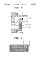
- FIG. 6 is a vertical sectional view of an exhaust manifold in the third embodiment of the present invention.
- FIG. 7 is a sectional view of an adsorber taken along the line VII--VII of FIG. 6;
- FIG. 8 is a schematic plan view with partial cross section of an engine provided with an adsorber, which is the fourth embodiment of the present invention.
- FIG. 9 is a break perspective view of the adsorber
- FIG. 10 is an end view taken along the line X--X of FIG. 9;
- FIG. 11 is an exploded perspective view of the catalyst carrier
- FIG. 12 is a schematic plan view, partially in cross section of an engine provided with an adsorber, which is the fifth embodiment of the present invention.
- a vehicle engine with four cylinders 1 has four exhaust ports 1a, 1b, 1c and 1d.
- the exhaust gas (represented by broken lines in the figure) exhausted from the exhaust ports 1a to 1d is collected in the exhaust manifold 11 to effuse into the exhaust pipe 3 connected to the exhaust manifold 11.
- the main catalyst 31 is located in the exhaust pipe 3.
- the adsorber 200 has a vessel 2 disposed along the sidewall of the engine 1 to cover and face the exhaust ports 1a to 1d. As shown in FIG. 2, the vessel 2 forms a dead-end box opened toward the exhaust ports 1a to 1d, and is welded securely to the outer wall of the exhaust manifold 11 to form part of the outer wall.
- the current in the exhaust manifold 11 passes through the exhaust port 1b toward the exit 111 along the curved path as shown in FIG. 2.
- the vessel 2 which has a rectangular shape in the front view from the exhaust ports 1a to 1d (as shown in FIG. 3), has an opening 22 extending longitudinally at the top wall.
- the opening 22 connects with an opening 112 disposed at the wall of the exhaust manifold 11.
- the catalyst carrier 21, which serves also as an adsorbent, is accommodated in the vessel 2 as shown in FIG. 4.
- the adsorbent is formed by alternately placing plane and corrugated plates.
- plane plates 211 and corrugated plates 212 are made of foil having a plate thickness of approximately 50 micrometers which is composed of 20% chromium (Cr), 5% aluminum (Al) and 75% iron (Fe). These plates are connected with each other by brazing, etc.
- Two rows of the corrugated plates 212 are disposed on the plane plate 211.
- An opening 215 formed by the plane plate 211 and corrugated plate 212 faces to the exhaust ports 1a to 1d.
- the plane plates 211 are cut in the form of a louver 213 at several points in the longitudinal direction, to serve as flow holes 214 connecting in a vertical direction.
- the flow holes 214 connect with the opening 22 disposed at the top wall of the vessel 2 (FIG. 2).
- the plane plates 211 and corrugated plates 212 of the carrier 21 are coated with activated alumina, etc., and contain noble metals such as platinum (Pt) or palladium (Pd) which are catalyst compositions.
- noble metals such as platinum (Pt) or palladium (Pd) which are catalyst compositions.
- Most of the exhaust gas exhausted from the left side of the figure changes its direction to flow upward as represented by the broken lines in FIG. 2, and effuse from the exit 111 into the exhaust pipe 3.
- the other of the exhaust gas flows between the plane plates 211 and corrugated plates 212 in the carrier 21, and is guided upward by the louvers 213 to effuse from the flow holes 214 into the exit 111 passing through the opening 22.
- the exhaust material exhausted immediately after startup of the engine is exhausted rectilinearly from the exhaust ports 1a to 1d due to its inertia because the exhaust material has high specific gravity, and directly enters the adsorber.
- the exhaust gas is pulsated immediately after startup, in other words the exhaust gas enters the adsorber intermittenly during idling. Therefore the carrier 21 captures the exhaust material on the wide range of catalyst surface by pulsated exhaust gas during idling, as represented by the continuous lines in FIGS. 1 and 2.
- the temperature of the adsorber in the manifold 11 rises.
- the temperature reaches the temperature required for activating the catalyst the exhaust material adsorbed on the catalyst is purified while it is vaporized by heat and effused through the exit 111. Since the flow holes 214 are covered by the louvers 213, the surface of the adsorber does not decrease if the flow holes 214 are disposed, making it possible to obtain sufficient purification effect.
- the unburned fuel exhausted immediately after startup of the engine is captured sufficiently using the adsorber and exhausted with purified condition, making it possible to greatly improve the exhaust emission.
- the adsorber In the adsorber, only the part of the exhaust gas flows. In other words, since the engine is warmed up and the rotation of the engine is much higher than the idling, the exhaust gas flows continuously.
- the adsorber is always pressurized by the exhaust gas. In and out flow of exhaust gas does not occur. Therefore the adsorber does not adsorb the exhaust gas under such pressurized condition.
- the temperature of the adsorber does not become so high even when high-temperature exhaust gas occurs at high engine load, making it possible to prevent the damage of the adsorber.
- the temperature of the exhaust gas is about 850° C.
- the temperature of the exhaust manifold at the place where all exhaust gas gather is about 900° C.
- the outer surface of the adsorber which receives the exhaust gas directly has almost same temperature but the interior surface of the adsorber which is in the middle between the outer surface and furthest portion of the adsorber has about 750° C.
- the adsorber releases heat outside.
- the carrier 21 contains the catalyst to serve as an adsorbent.
- a simple adsorber such as zeolite may be used.
- the unburned fuel dissociated from the adsorbent due to the increase in the temperature flows from the exhaust manifold 11 into the exhaust pipe 3 (FIG. 1) and is cleaned by the main catalyst 31 in the exhaust pipe 3 where the temperature reaches the temperature required for activating.
- the carrier 21 may be made of the ceramic honeycomb, etc., instead of the metallic foil. Also, pellet catalyst in which ceramic particles contain catalyst may be used instead of the honeycomb carrier. Activated alumina, zeolite, etc., which have large surface areas may be used instead of the catalyst.
- the flow holes 214 disposed at the plane plates 211 of the carrier 21 can be replaced with a large number of pores 215 as shown in FIG. 5, making it possible to obtain the same effect.
- the opening of the vessel 2 and the opening of the exhaust manifold 11 are reduced, because the amount of the unburned fuel exhausted is comparatively small in high speed engines, etc. Since the gas does not flow in the adsorber at all, this adsorber has high structural durability.
- FIG. 8 In the fourth embodiment of the present invention as shown in FIG. 8, several vessels 2 are disposed at the outer wall of the exhaust manifold 11 facing the exhaust ports 1a to 1d of the engine 1, with their openings directed toward each exhaust port 1a to 1d.
- the carrier 21 is stored in the vessel 2. The details of this embodiment are shown in FIGS. 9 and 10.
- the honeycomb carrier 21 is disposed in the circular vessel 2 which is opened upward.
- the carriers 21 are constructed by accumulating the plane plates 211 and corrugated plates 212 alternately in the form of a spiral and connected by brazing.
- the flow holes which connect with the exit 111 of the exhaust manifold 11 may be disposed at each vessel 2 in the same manner as in the first embodiment.
- the current passages 113 and 114 which have longer sectional area are formed between the left two vessels 2 and right two vessels 2, respectively, with directed toward the exit 111 in the exhaust manifold 11. Therefore, the exhaust gas from the exhaust ports 1a and 1d is smoothly guided toward the exit 111 passing through the flow passages 113 and 114, respectively, without greatly bending in the same manner as in the above described embodiments (represented by the broken lines).
- the material exhausted from the engine is assumed to be unburned fuel.
- the present invention can be applied to other materials such as carbon exhausted from the engine to obtain the same effect as in the above described embodiments.
- each two of the circular vessels 2 may be connected with each pipe, and further all circular vessels 2 may be connected with one pipe to lead out and in exhaust gas from one vessel to other vessels to improve the adsorbing efficiency.
- the carriers 21 may be disposed in the circular vessels 2 in such a manner to maintain a space inside the vessels 2 between the carriers 21 and the outer wall of the exhaust manifold to which the pipe is connected.
Abstract
Description
Claims (11)
Applications Claiming Priority (2)
| Application Number | Priority Date | Filing Date | Title |
|---|---|---|---|
| JP05026087A JP3116628B2 (en) | 1993-01-21 | 1993-01-21 | Suction device |
| JP5-026087 | 1993-01-21 |
Publications (1)
| Publication Number | Publication Date |
|---|---|
| US5493859A true US5493859A (en) | 1996-02-27 |
Family
ID=12183836
Family Applications (1)
| Application Number | Title | Priority Date | Filing Date |
|---|---|---|---|
| US08/183,944 Expired - Fee Related US5493859A (en) | 1993-01-21 | 1994-01-21 | Engine with an adsorber |
Country Status (2)
| Country | Link |
|---|---|
| US (1) | US5493859A (en) |
| JP (1) | JP3116628B2 (en) |
Cited By (13)
| Publication number | Priority date | Publication date | Assignee | Title |
|---|---|---|---|---|
| US5653105A (en) * | 1994-12-19 | 1997-08-05 | Automobiles Peugeot | Device for the treatment of the exhaust gases of a spark-ignition engine comprising a catalyst body and a hydrocarbons adsorber placed in an exhaust manifold |
| US5701736A (en) * | 1994-12-19 | 1997-12-30 | Nippon Soken, Inc. | Apparatus for purifying exhaust gas |
| US5797263A (en) * | 1995-02-08 | 1998-08-25 | Nippon Soken, Inc. | Exhaust emission control apparatus |
| US6244044B1 (en) | 1999-09-20 | 2001-06-12 | Southwest Research Institute | Method for reducing cold-start hydrocarbon emissions in a gasoline, natural gas, or propane fueled engine |
| EP1342496A2 (en) * | 1996-08-19 | 2003-09-10 | Volkswagen AG | Spark-ignited internal combustion engine with an NOx-adsorber |
| US20040060283A1 (en) * | 2000-12-05 | 2004-04-01 | Ju-Chel Lee | Exhaust gas control device for internal combustion engines |
| EP1489292A1 (en) * | 2003-06-18 | 2004-12-22 | DaimlerChrysler AG | Internal combustion engine with an adsorption/absorption element |
| US20050005597A1 (en) * | 2001-04-12 | 2005-01-13 | Emitec Gesellschaft Fur Emissionstechnologie Mbh | Exhaust system |
| EP1520973A2 (en) * | 2003-10-02 | 2005-04-06 | DaimlerChrysler AG | Internal combustion engine with exhaust pipe |
| WO2005064131A1 (en) * | 2003-12-25 | 2005-07-14 | Toyota Jidosha Kabushiki Kaisha | Apparatus for purifying exhaust gas |
| US20090094966A1 (en) * | 2007-10-15 | 2009-04-16 | International Engine Intellectual Property Company, Llc | Aftertreatment device |
| US20110053342A1 (en) * | 2008-02-13 | 2011-03-03 | Radouane Khalid | Semiconductor substrate surface preparation method |
| US20160230629A1 (en) * | 2013-09-17 | 2016-08-11 | Jaguar Land Rover Limited | Exhaust treatment apparatus and method |
Citations (10)
| Publication number | Priority date | Publication date | Assignee | Title |
|---|---|---|---|---|
| US3173451A (en) * | 1960-06-23 | 1965-03-16 | Owens Corning Fiberglass Corp | Cast manifold with liner |
| US3644098A (en) * | 1969-09-18 | 1972-02-22 | Universal Oil Prod Co | Catalytic converter for exhaust gases |
| US3804597A (en) * | 1971-09-20 | 1974-04-16 | Toyota Motor Co Ltd | Exhaust emission control device for an internal combustion engine |
| US3807173A (en) * | 1971-03-23 | 1974-04-30 | Owens Illinois Inc | Exhaust reactor for combustion engine |
| US3881316A (en) * | 1971-04-16 | 1975-05-06 | Toyota Motor Co Ltd | Exhaust gas purifying device for an internal combustion engine |
| US3972184A (en) * | 1972-04-20 | 1976-08-03 | Ethyl Corporation | Catalytic treatment of exhaust gas responsive to engine temperature |
| US4735046A (en) * | 1985-06-08 | 1988-04-05 | Sanshin Kogyo Kabushiki Kaisha | Oil remover from exhaust gas of marine propulsion unit |
| US4887427A (en) * | 1985-10-28 | 1989-12-19 | Nissan Motor Company, Limited | Exhaust particle removing system for an engine |
| US4924820A (en) * | 1987-09-04 | 1990-05-15 | Orbital Engine Company Proprietary Limited | Exhaust gas treatment for a two stroke engine |
| US5209062A (en) * | 1990-07-27 | 1993-05-11 | Sulzer Brothers Limited | Large diesel engine |
-
1993
- 1993-01-21 JP JP05026087A patent/JP3116628B2/en not_active Expired - Fee Related
-
1994
- 1994-01-21 US US08/183,944 patent/US5493859A/en not_active Expired - Fee Related
Patent Citations (10)
| Publication number | Priority date | Publication date | Assignee | Title |
|---|---|---|---|---|
| US3173451A (en) * | 1960-06-23 | 1965-03-16 | Owens Corning Fiberglass Corp | Cast manifold with liner |
| US3644098A (en) * | 1969-09-18 | 1972-02-22 | Universal Oil Prod Co | Catalytic converter for exhaust gases |
| US3807173A (en) * | 1971-03-23 | 1974-04-30 | Owens Illinois Inc | Exhaust reactor for combustion engine |
| US3881316A (en) * | 1971-04-16 | 1975-05-06 | Toyota Motor Co Ltd | Exhaust gas purifying device for an internal combustion engine |
| US3804597A (en) * | 1971-09-20 | 1974-04-16 | Toyota Motor Co Ltd | Exhaust emission control device for an internal combustion engine |
| US3972184A (en) * | 1972-04-20 | 1976-08-03 | Ethyl Corporation | Catalytic treatment of exhaust gas responsive to engine temperature |
| US4735046A (en) * | 1985-06-08 | 1988-04-05 | Sanshin Kogyo Kabushiki Kaisha | Oil remover from exhaust gas of marine propulsion unit |
| US4887427A (en) * | 1985-10-28 | 1989-12-19 | Nissan Motor Company, Limited | Exhaust particle removing system for an engine |
| US4924820A (en) * | 1987-09-04 | 1990-05-15 | Orbital Engine Company Proprietary Limited | Exhaust gas treatment for a two stroke engine |
| US5209062A (en) * | 1990-07-27 | 1993-05-11 | Sulzer Brothers Limited | Large diesel engine |
Cited By (21)
| Publication number | Priority date | Publication date | Assignee | Title |
|---|---|---|---|---|
| US5701736A (en) * | 1994-12-19 | 1997-12-30 | Nippon Soken, Inc. | Apparatus for purifying exhaust gas |
| US5873242A (en) * | 1994-12-19 | 1999-02-23 | Nippon Soken. Inc. | Apparatus for purifying exhaust gas |
| US5653105A (en) * | 1994-12-19 | 1997-08-05 | Automobiles Peugeot | Device for the treatment of the exhaust gases of a spark-ignition engine comprising a catalyst body and a hydrocarbons adsorber placed in an exhaust manifold |
| US5797263A (en) * | 1995-02-08 | 1998-08-25 | Nippon Soken, Inc. | Exhaust emission control apparatus |
| EP1342496A2 (en) * | 1996-08-19 | 2003-09-10 | Volkswagen AG | Spark-ignited internal combustion engine with an NOx-adsorber |
| EP1342496A3 (en) * | 1996-08-19 | 2003-09-24 | Volkswagen AG | Spark-ignited internal combustion engine with an NOx-adsorber |
| US6244044B1 (en) | 1999-09-20 | 2001-06-12 | Southwest Research Institute | Method for reducing cold-start hydrocarbon emissions in a gasoline, natural gas, or propane fueled engine |
| US7007459B2 (en) * | 2000-12-05 | 2006-03-07 | Ju-Cheol Lee | Exhaust gas control device for internal combustion engines |
| US20040060283A1 (en) * | 2000-12-05 | 2004-04-01 | Ju-Chel Lee | Exhaust gas control device for internal combustion engines |
| US20050005597A1 (en) * | 2001-04-12 | 2005-01-13 | Emitec Gesellschaft Fur Emissionstechnologie Mbh | Exhaust system |
| US8166750B2 (en) * | 2001-04-12 | 2012-05-01 | Emitec Gesellschaft Fuer Emissionstechnologie Mbh | Exhaust system |
| EP1489292A1 (en) * | 2003-06-18 | 2004-12-22 | DaimlerChrysler AG | Internal combustion engine with an adsorption/absorption element |
| EP1520973A2 (en) * | 2003-10-02 | 2005-04-06 | DaimlerChrysler AG | Internal combustion engine with exhaust pipe |
| EP1520973A3 (en) * | 2003-10-02 | 2005-04-13 | DaimlerChrysler AG | Internal combustion engine with exhaust pipe |
| WO2005064131A1 (en) * | 2003-12-25 | 2005-07-14 | Toyota Jidosha Kabushiki Kaisha | Apparatus for purifying exhaust gas |
| US20090094966A1 (en) * | 2007-10-15 | 2009-04-16 | International Engine Intellectual Property Company, Llc | Aftertreatment device |
| US20110053342A1 (en) * | 2008-02-13 | 2011-03-03 | Radouane Khalid | Semiconductor substrate surface preparation method |
| US8062957B2 (en) * | 2008-02-13 | 2011-11-22 | S.O.I.Tec Silicon On Insulator Technologies | Semiconductor substrate surface preparation method |
| US20160230629A1 (en) * | 2013-09-17 | 2016-08-11 | Jaguar Land Rover Limited | Exhaust treatment apparatus and method |
| US9803526B2 (en) * | 2013-09-17 | 2017-10-31 | Jaguar Land Rover Limited | Exhaust treatment apparatus and method |
| US9957866B2 (en) | 2013-09-17 | 2018-05-01 | Jaguar Land Rover Limited | Exhaust treatment apparatus and method |
Also Published As
| Publication number | Publication date |
|---|---|
| JPH06212951A (en) | 1994-08-02 |
| JP3116628B2 (en) | 2000-12-11 |
Similar Documents
| Publication | Publication Date | Title |
|---|---|---|
| US5493859A (en) | Engine with an adsorber | |
| US9341096B2 (en) | Exhaust gas treatment device for use near an engine and motor vehicle having the device | |
| US4934142A (en) | Exhaust emission control device for a diesel engine | |
| US6820417B2 (en) | Exhaust aftertreatment system and method for an internal combustion engine | |
| KR101095329B1 (en) | Off-line filter with improved filter efficiency | |
| US3247665A (en) | Catalytic muffler construction for exhaust emission control in an internal combustion engine system | |
| CN102071992A (en) | Exhaust particulate management for gasoline-fueled engines | |
| JPS649447B2 (en) | ||
| US20170204813A1 (en) | Engine exhaust gas recirculation system with at least one exhaust recirculation treatment device | |
| CA2009165A1 (en) | Catalyst for purification of exhaust gas from diesel engine | |
| JPH1054220A (en) | Exhaust emission control device for diesel engine | |
| JP2005214159A (en) | Exhaust emission control device | |
| US5440083A (en) | Exhaust muffler for internal combustion engine | |
| EP0945178B1 (en) | Exhaust emission control catalyst for diesel engines | |
| WO2003069139A1 (en) | A device for treatment of a gas flow | |
| US20060254263A1 (en) | Flow reversal in exhaust system including filter | |
| US5214020A (en) | Backwash type particulate filter | |
| US4895707A (en) | Soot burn-off filter for diesel engines | |
| EP1101907A1 (en) | Exhaust gas emission-control system | |
| US5265419A (en) | Soot-particle filter for after-treatment of the exhaust gases of diesel engines | |
| JP5409984B2 (en) | Exhaust gas purification device using selective reduction catalyst | |
| EP0753650A1 (en) | Exhaust gas purification apparatus | |
| JPH0631121A (en) | Honeycomb filter | |
| US9421488B2 (en) | Cleanable particle separator and motor vehicle having at least one particle separator | |
| US20010001646A1 (en) | Method of preparing a catalytic device and after-treating apparatus of exhaust gas using the catalytic device |
Legal Events
| Date | Code | Title | Description |
|---|---|---|---|
| AS | Assignment |
Owner name: NIPPONDENSO CO., LTD., JAPAN Free format text: ASSIGNMENT OF ASSIGNORS INTEREST;ASSIGNORS:SHINOHARA, YUKIHIRO;IGASHIRA, TOSHIHIKO;YOSHINAGA, TOHRU;AND OTHERS;REEL/FRAME:006849/0551;SIGNING DATES FROM 19940111 TO 19940113 |
|
| FEPP | Fee payment procedure |
Free format text: PAYOR NUMBER ASSIGNED (ORIGINAL EVENT CODE: ASPN); ENTITY STATUS OF PATENT OWNER: LARGE ENTITY |
|
| AS | Assignment |
Owner name: NIPPON SOKEN, INC, JAPAN Free format text: ASSIGNMENT OF ASSIGNORS INTEREST;ASSIGNOR:NIPPONDENSO CO., LTD.;REEL/FRAME:007908/0805 Effective date: 19960416 |
|
| FPAY | Fee payment |
Year of fee payment: 4 |
|
| FPAY | Fee payment |
Year of fee payment: 8 |
|
| REMI | Maintenance fee reminder mailed | ||
| LAPS | Lapse for failure to pay maintenance fees | ||
| STCH | Information on status: patent discontinuation |
Free format text: PATENT EXPIRED DUE TO NONPAYMENT OF MAINTENANCE FEES UNDER 37 CFR 1.362 |
|
| FP | Lapsed due to failure to pay maintenance fee |
Effective date: 20080227 |