US549254A - Method of making insulator-rings - Google Patents
Method of making insulator-rings Download PDFInfo
- Publication number
- US549254A US549254A US549254DA US549254A US 549254 A US549254 A US 549254A US 549254D A US549254D A US 549254DA US 549254 A US549254 A US 549254A
- Authority
- US
- United States
- Prior art keywords
- ring
- mica
- rings
- shape
- die
- Prior art date
- Legal status (The legal status is an assumption and is not a legal conclusion. Google has not performed a legal analysis and makes no representation as to the accuracy of the status listed.)
- Expired - Lifetime
Links
- 238000004519 manufacturing process Methods 0.000 title description 3
- 239000010445 mica Substances 0.000 description 21
- 229910052618 mica group Inorganic materials 0.000 description 21
- 230000001788 irregular Effects 0.000 description 6
- 238000000034 method Methods 0.000 description 6
- 239000004568 cement Substances 0.000 description 5
- 239000007787 solid Substances 0.000 description 4
- 229920001800 Shellac Polymers 0.000 description 3
- 230000000284 resting effect Effects 0.000 description 3
- 229940113147 shellac Drugs 0.000 description 3
- 239000004208 shellac Substances 0.000 description 3
- 239000012212 insulator Substances 0.000 description 2
- 239000000853 adhesive Substances 0.000 description 1
- 230000001070 adhesive effect Effects 0.000 description 1
- 238000005452 bending Methods 0.000 description 1
- 238000005266 casting Methods 0.000 description 1
- 230000006835 compression Effects 0.000 description 1
- 238000007906 compression Methods 0.000 description 1
- 238000010276 construction Methods 0.000 description 1
- 238000001035 drying Methods 0.000 description 1
- 230000005520 electrodynamics Effects 0.000 description 1
- 238000001704 evaporation Methods 0.000 description 1
- 238000010438 heat treatment Methods 0.000 description 1
- 239000000463 material Substances 0.000 description 1
- 238000003825 pressing Methods 0.000 description 1
- ZLGIYFNHBLSMPS-ATJNOEHPSA-N shellac Chemical compound OCCCCCC(O)C(O)CCCCCCCC(O)=O.C1C23[C@H](C(O)=O)CCC2[C@](C)(CO)[C@@H]1C(C(O)=O)=C[C@@H]3O ZLGIYFNHBLSMPS-ATJNOEHPSA-N 0.000 description 1
- 235000013874 shellac Nutrition 0.000 description 1
- 239000002904 solvent Substances 0.000 description 1
- 239000000126 substance Substances 0.000 description 1
Images


Classifications
-
- H—ELECTRICITY
- H01—ELECTRIC ELEMENTS
- H01T—SPARK GAPS; OVERVOLTAGE ARRESTERS USING SPARK GAPS; SPARKING PLUGS; CORONA DEVICES; GENERATING IONS TO BE INTRODUCED INTO NON-ENCLOSED GASES
- H01T13/00—Sparking plugs
- H01T13/02—Details
- H01T13/16—Means for dissipating heat
-
- H—ELECTRICITY
- H01—ELECTRIC ELEMENTS
- H01B—CABLES; CONDUCTORS; INSULATORS; SELECTION OF MATERIALS FOR THEIR CONDUCTIVE, INSULATING OR DIELECTRIC PROPERTIES
- H01B3/00—Insulators or insulating bodies characterised by the insulating materials; Selection of materials for their insulating or dielectric properties
- H01B3/02—Insulators or insulating bodies characterised by the insulating materials; Selection of materials for their insulating or dielectric properties mainly consisting of inorganic substances
- H01B3/04—Insulators or insulating bodies characterised by the insulating materials; Selection of materials for their insulating or dielectric properties mainly consisting of inorganic substances mica
-
- Y—GENERAL TAGGING OF NEW TECHNOLOGICAL DEVELOPMENTS; GENERAL TAGGING OF CROSS-SECTIONAL TECHNOLOGIES SPANNING OVER SEVERAL SECTIONS OF THE IPC; TECHNICAL SUBJECTS COVERED BY FORMER USPC CROSS-REFERENCE ART COLLECTIONS [XRACs] AND DIGESTS
- Y10—TECHNICAL SUBJECTS COVERED BY FORMER USPC
- Y10T—TECHNICAL SUBJECTS COVERED BY FORMER US CLASSIFICATION
- Y10T156/00—Adhesive bonding and miscellaneous chemical manufacture
- Y10T156/10—Methods of surface bonding and/or assembly therefor
- Y10T156/1002—Methods of surface bonding and/or assembly therefor with permanent bending or reshaping or surface deformation of self sustaining lamina
- Y10T156/1043—Subsequent to assembly
Definitions
- This invention relates to flanged insulatorrings made of built-up laminae or pieces of mica.
- the invention has for its object to simplify and cheapen the process of making flanged insulator-rings of built-up pieces of mica and thereby provide such rings of irregular shape in one solid piece without seam or joint. These rings are especially adapted for armatures of electrodynamic machines.
- This invention consists of a method of forming flanged insulator-rings of built-up pieces of mica, as hereinafter set forth and claimed.
- the difficulty with and objection to this method are that the mica scales being very brittle and unyielding, and being connected together with overlapping edges by the cement, will move apart and get out of place when pressure is applied with a mold and cannot be uniformly bent into the irregular shape and flanged form desired without either breaking or being separated from their built-up position, thereby leaving seams and cracks and not affording a solid flanged ring in one piece.
- This invention is therefore intended as an improvement on the foregoing method, obviating such difficulty and objection and providing a solid flanged ring or ring of irregular shape in one piece of builtup mica.
- This invention is carried out as follows: Pieces or scales of mica are built up by hand and assembled over a mold into the desired shape, the pieces being cemented together by gum-shellac or other suitable binding medium and conforming to the curved parts and other irregular portions of the mold. The ring so formed is then placed in a suitable press conforming to the shape of the ring and pressure and heat are applied, the cement becoming dried and fiXed and the ring cooled in the well-known way in this art.
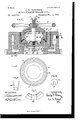
- FIG. 1 Sheet 1 is a face view of a scale or piece of mica of an outline suitable to conform to the shape of the ring to be formed.
- Fig. 2 Sheet 1 is a View in perspective of the scale or piece of mica shown in Fig. 1 bent into shape by hand.
- Fig. 3 Sheet 1, shows, partly in vertical section on the line :20 as, Fig. 4, the mold and a flanged ring resting thereon formed of pieces of mica, shown in Fig. 1, bent by hand and assembled into the shape shown in Fig. 2 over a mold.
- Fig. at is a plan View of the flanged ring formed as indicated in Fig. Fig.
- FIG. 5 is a view in vertical section of a press for forming the. complete flanged ring from the incomplete ring in Fig. 4 of the outline as shown in heavy black lines in Fig. 5.
- Fig. 6 is a plan View of the lower die of the press.
- Fig. 7 is a plan View of a portion of the upper die and one of the expanding-wedges.
- Fig. Sis a View in elevation of one of the expanding-wedges.
- Fig. 9 is a detail view of apart shown in Fig. 5, and Fig. 10 is a plan view of the completed ring. r
- the press is constructed as follows: 5 is the frame of the press, formed of a circular casting, provided with the circumferential passages 6 7 for the circulation of steam or other heating medium admitted thereto through the inlet-pipe 9 and having its outlet through the discharge-pipe S. ⁇ Vithin a circular chamber in the frame 5 is located a removable circular receptacle 10, in which is located a circular flanged die 11, forming the lower die of the press, the upper die 12, in the form of a ring, resting upon and fitting over the die 11.
- the transverse meeting surfaces of the dies may be of any corresponding irregular shape desired, while the side adjacent surfaces are vertical planes slightly at an angle.
- the transverse meeting surfaces are of such shape as to form a hook or bent-over end at the edge of the inwardly-inclined flange of the ring 4.
- the plunger 13 Upon the top, adjacent to the inner edge of the die 12, rests the plunger 13 having an inclined bearing portion 14: of its surface resting against .a correspondingly inclined surface 15 of the disk 12. 13 extends an upright post 16, upon which the plunger is vertically movable, the lower end of the upright post 16 being fixed in the bottom of the receptacle 10.
- the plunger 13 is forced down to compress the die 1.2 against the die 11 by means of the wheel-handle l7, turning on the screw-threaded portion 18 of the post 16 and bearing on the plunger 13.
- a vertically-movable rod 19 is located in and extends through a passage-way in the post 16, having a head 20 at its upper end and a frame 21 mounted on its lower end and secured thereto loya nut 22.
- the frame 21 is provided with upwardly-extending projections 24:, having their upper ends located in and adapted to move up Through the plunger
- the frame 21 is located through holes or passage-ways 25 in the bot tom of the receptacle 10.
- a metallic disk 26 having the slot 27, as shown in Fig. 9, by means of which it is slipped over the rod 19 and rests on the upper end of post 16.
- the lower die 11 may be released by turning the wheel-handle 17 upward until it bears against the under side of disk 26, when the upward pressure, upon furtherturnin g of the wheel-handle 17, causes the frame 21 to be lifted up and through the projections 24 to raise up and release the lower (hell.
- the die 11 may be made in sections, as indicated at the points a, Fig. 6.
- the disk 12 is preferably made in sections, and between the sections are placed wedges 28, as shown in Fig. 7, which are forced into position to expand the die 12. It will readily be seen that with the shape and arrangement of the bearing-surfaces of the die 12 and the plunger 13 the made-up insulatorring 29 will be effectively compressed into a compact form of the desired shape.
- a flanged insulator-ring being formed on the mold 2 by hand in the shape shown in Figs. 3 and 4, as already set forth, the disk 26, wheel-handle 17, plunger 13, and die 12 are removed, the ring 4 is placed in the die 1 l, and the above parts are replaced. Pressure being applied by means of the wheel 17 the ring 4 is pressed into the shape of the ring 29. Steam being constantly admitted before and during the operation of the press, the
Landscapes
- Chemical & Material Sciences (AREA)
- Inorganic Chemistry (AREA)
- Insulating Bodies (AREA)
Description
3 Sheets-Sheet 1.
(No Model.)
0. F. PETERSON.
METHOD OF MAKING INSULATOR RINGS.
Patented Nov. 5,1895.
' ITEZ- FIE .1-
3 SheetsSheet 2.
(No Model.)
0. F. PETERSON. METHOD OF MAKING INSULATOR RINGS.
U0 Patented Nov. 5,1895.
gg-fi V 2.1
, 6 nm n7 W n DLTMQWASHINGTONJC (NoModeL) v a Sheets-Shget 3.
O. E. PETERSON. METHOD OI MAKING INSULATOR RINGS. No. 549,254. Patented N0v.'5,1895.
ANQREW B GRANAM PHfiG-HTHQ WAimHsToNJic UNITED. STATES PATENT OFFICE.
CHARLES F. PETERSON, OF SCHENECTADY, NEIV YORK, ASSIGNOR TO THE GENERAL ELECTRIC COMPANY, OF NEW YORK.
METHOD OF MAKING lNSULATOR-RINGS.
SPECIFICATION forming part of Letters Patent No. 549,254, dated November 5, 1895.
. Application filed June 1, 1895. Serial No. 551,3 71. (N0 specimens.)
To all whom it Wmy concern.-
Be it known that 1, CHARLES FREDRIK PETERSON, a citizen of the United States, residing at Schenectady, in the county of Schenectady, State of New York, have invented certain new and useful Improvements in the Method of Making Insulator-Rings, of which the following is a specification.
This invention relates to flanged insulatorrings made of built-up laminae or pieces of mica.
The invention has for its object to simplify and cheapen the process of making flanged insulator-rings of built-up pieces of mica and thereby provide such rings of irregular shape in one solid piece without seam or joint. These rings are especially adapted for armatures of electrodynamic machines.
This invention consists of a method of forming flanged insulator-rings of built-up pieces of mica, as hereinafter set forth and claimed.
It is a common practice in the art to form built-up mica sheets by placing pieces or laminae of mica in a sheet overlapping one another and securing them together by gum, shellac, or other suitable adhesive substance. In order to provide flanged insulator-rings of such material, it has been proposed to form such rings by making an annular disk of such built-up mica and by means of a suitable mold pressing s uch annular disk into the shape of a flanged ring, or, in other words, building a mica sheet by cementing together laminae of mica scales with overlapping edges, compressing the sheet into the desired form while the cement is wet, drying the cement by evaporating the solvent thereof, and finally chilling the molded mica sheet while under compression. The difficulty with and objection to this method are that the mica scales being very brittle and unyielding, and being connected together with overlapping edges by the cement, will move apart and get out of place when pressure is applied with a mold and cannot be uniformly bent into the irregular shape and flanged form desired without either breaking or being separated from their built-up position, thereby leaving seams and cracks and not affording a solid flanged ring in one piece.
This invention is therefore intended as an improvement on the foregoing method, obviating such difficulty and objection and providing a solid flanged ring or ring of irregular shape in one piece of builtup mica.
This invention is carried out as follows: Pieces or scales of mica are built up by hand and assembled over a mold into the desired shape, the pieces being cemented together by gum-shellac or other suitable binding medium and conforming to the curved parts and other irregular portions of the mold. The ring so formed is then placed in a suitable press conforming to the shape of the ring and pressure and heat are applied, the cement becoming dried and fiXed and the ring cooled in the well-known way in this art.
To illustrate the manner of carrying out this invention, reference is had to the accompanying drawings, in Which Figure 1, Sheet 1, is a face view of a scale or piece of mica of an outline suitable to conform to the shape of the ring to be formed. Fig. 2, Sheet 1, is a View in perspective of the scale or piece of mica shown in Fig. 1 bent into shape by hand. Fig. 3, Sheet 1, shows, partly in vertical section on the line :20 as, Fig. 4, the mold and a flanged ring resting thereon formed of pieces of mica, shown in Fig. 1, bent by hand and assembled into the shape shown in Fig. 2 over a mold. Fig. at is a plan View of the flanged ring formed as indicated in Fig. Fig. 5 is a view in vertical section of a press for forming the. complete flanged ring from the incomplete ring in Fig. 4 of the outline as shown in heavy black lines in Fig. 5. Fig. 6 is a plan View of the lower die of the press. Fig. 7 is a plan View of a portion of the upper die and one of the expanding-wedges. Fig. Sis a View in elevation of one of the expanding-wedges. Fig. 9 is a detail view of apart shown in Fig. 5, and Fig. 10 is a plan view of the completed ring. r
In carrying out this process scales or pieces of mica 1, preferably of the shape shown in Fig. 1-2'. 6., quadrangular With inclined sidesare bent by hand, as shown in Fig. 2, over a mold 2 (shown in Fig. 3) with an inwardly flaring or inclined flange 3, and assembled in the shape of a flanged ring 4, (shown in Fig. 4,) the pieces or scales of mica 1 overlapping each other so as to break joints, the outer and inner surfaces of the ring 4 presenting a smooth surface. In this construction the curves of the ring, being formed of the bend in the pieces of mica, will prevent any crack or seam being located at the joint, thereby affording a practically solid piece at those points. In assembling the bent pieces 1 in this manner they are stuck to gether by gum-shellac or other suitable binding medium, and when the ring 4 is completed it is removed from the mold 2 and placed in the press. (Shown in Fig. 5.)
The press is constructed as follows: 5 is the frame of the press, formed of a circular casting, provided with the circumferential passages 6 7 for the circulation of steam or other heating medium admitted thereto through the inlet-pipe 9 and having its outlet through the discharge-pipe S. \Vithin a circular chamber in the frame 5 is located a removable circular receptacle 10, in which is located a circular flanged die 11, forming the lower die of the press, the upper die 12, in the form of a ring, resting upon and fitting over the die 11. The transverse meeting surfaces of the dies may be of any corresponding irregular shape desired, while the side adjacent surfaces are vertical planes slightly at an angle. As here shown, the transverse meeting surfaces are of such shape as to form a hook or bent-over end at the edge of the inwardly-inclined flange of the ring 4. Upon the top, adjacent to the inner edge of the die 12, rests the plunger 13 having an inclined bearing portion 14: of its surface resting against .a correspondingly inclined surface 15 of the disk 12. 13 extends an upright post 16, upon which the plunger is vertically movable, the lower end of the upright post 16 being fixed in the bottom of the receptacle 10. The plunger 13 is forced down to compress the die 1.2 against the die 11 by means of the wheel-handle l7, turning on the screw-threaded portion 18 of the post 16 and bearing on the plunger 13.
To release the lower die 11 after the operation, the following device may be employed: A vertically-movable rod 19 is located in and extends through a passage-way in the post 16, having a head 20 at its upper end and a frame 21 mounted on its lower end and secured thereto loya nut 22.
in an opening 23 in the base of the frame 5. The frame 21 is provided with upwardly-extending projections 24:, having their upper ends located in and adapted to move up Through the plunger The frame 21 is located through holes or passage-ways 25 in the bot tom of the receptacle 10. Upon the top of the post 16 is located a metallic disk 26, having the slot 27, as shown in Fig. 9, by means of which it is slipped over the rod 19 and rests on the upper end of post 16. After the insulator-ring has been compressed between the dies the lower die 11 may be released by turning the wheel-handle 17 upward until it bears against the under side of disk 26, when the upward pressure, upon furtherturnin g of the wheel-handle 17, causes the frame 21 to be lifted up and through the projections 24 to raise up and release the lower (hell.
The die 11 may be made in sections, as indicated at the points a, Fig. 6.
In order to afford lateral as well as vertical pressure on the ring to' be formed, the disk 12 is preferably made in sections, and between the sections are placed wedges 28, as shown in Fig. 7, which are forced into position to expand the die 12. It will readily be seen that with the shape and arrangement of the bearing-surfaces of the die 12 and the plunger 13 the made-up insulatorring 29 will be effectively compressed into a compact form of the desired shape.
A flanged insulator-ring being formed on the mold 2 by hand in the shape shown in Figs. 3 and 4, as already set forth, the disk 26, wheel-handle 17, plunger 13, and die 12 are removed, the ring 4 is placed in the die 1 l, and the above parts are replaced. Pressure being applied by means of the wheel 17 the ring 4 is pressed into the shape of the ring 29. Steam being constantly admitted before and during the operation of the press, the
' cement is evaporated and dried by the heat radiating through the press, and the mica scales are solidly secured together. The ring 29 is then removed and chilled and the ring is completed.
Having described my invention, I claim The herein described method of forming flanged insulator rings of built-up pieces of mica, which consists in bending pieces of mica, assembling them to form a predetermined shape, cementing them together as the irregular structure is built up, subjecting said structure to pressure and heat, and chilling the same.
In witness whereof I have hereunto set my hand this 22d day of May, 1895.
CHARLES F. PETERSON. lVitnesses I). B. HULL, A. F. MACDONALD.
Publications (1)
| Publication Number | Publication Date |
|---|---|
| US549254A true US549254A (en) | 1895-11-05 |
Family
ID=2617997
Family Applications (1)
| Application Number | Title | Priority Date | Filing Date |
|---|---|---|---|
| US549254D Expired - Lifetime US549254A (en) | Method of making insulator-rings |
Country Status (1)
| Country | Link |
|---|---|
| US (1) | US549254A (en) |
-
0
- US US549254D patent/US549254A/en not_active Expired - Lifetime
Similar Documents
| Publication | Publication Date | Title |
|---|---|---|
| US2422979A (en) | Apparatus for fabricating parts by bonding strips of material | |
| US881912A (en) | Die and method of making same. | |
| US941032A (en) | Process of manufacturing insulators. | |
| US1321517A (en) | House electric | |
| US566207A (en) | Press for dental flasks | |
| US551079A (en) | Sachusetts | |
| US1843904A (en) | Method of making molded wheels | |
| US1386512A (en) | Tire-mold | |
| US2625710A (en) | Mold structure | |
| US541890A (en) | Wood-bending machine | |
| US1584193A (en) | Method of molding or pressing and article | |
| US1158369A (en) | Bearing. | |
| CA1201272A (en) | Apparatus and method for breaking sand free from a pattern pocket in a mold | |
| US735579A (en) | Method of forming duplicate sound-record cylinders. | |
| US474661A (en) | Gustus holzapfel | |
| US560049A (en) | Manufacture of crockery washtubs | |
| US3089213A (en) | Apparatus for producing cementitious conduits | |
| US270704A (en) | Nathan w | |
| US639509A (en) | Apparatus for manufacturing glass pipe. | |
| US2089583A (en) | Fluid-tight winding for electric motors and method for the manufacture thereof | |
| US257992A (en) | Forming molds for castings | |
| US1636962A (en) | jacobson | |
| US785262A (en) | Molding-machine. | |
| US476799A (en) | Process of and machine for making emery-wheels | |
| US726644A (en) | Seamless gold crown for teeth. |