US548839A - Automatic weighing-machine - Google Patents
Automatic weighing-machine Download PDFInfo
- Publication number
- US548839A US548839A US548839DA US548839A US 548839 A US548839 A US 548839A US 548839D A US548839D A US 548839DA US 548839 A US548839 A US 548839A
- Authority
- US
- United States
- Prior art keywords
- valve
- movement
- opening
- closer
- bucket
- Prior art date
- Legal status (The legal status is an assumption and is not a legal conclusion. Google has not performed a legal analysis and makes no representation as to the accuracy of the status listed.)
- Expired - Lifetime
Links
- 230000033001 locomotion Effects 0.000 description 141
- 230000007246 mechanism Effects 0.000 description 38
- 230000000670 limiting effect Effects 0.000 description 16
- 208000028659 discharge Diseases 0.000 description 10
- 230000001360 synchronised effect Effects 0.000 description 10
- 230000001276 controlling effect Effects 0.000 description 7
- 239000000463 material Substances 0.000 description 6
- 230000000153 supplemental effect Effects 0.000 description 6
- 238000007599 discharging Methods 0.000 description 5
- 230000003534 oscillatory effect Effects 0.000 description 5
- 238000005303 weighing Methods 0.000 description 5
- 230000009471 action Effects 0.000 description 4
- 238000010276 construction Methods 0.000 description 4
- RUPBZQFQVRMKDG-UHFFFAOYSA-M Didecyldimethylammonium chloride Chemical compound [Cl-].CCCCCCCCCC[N+](C)(C)CCCCCCCCCC RUPBZQFQVRMKDG-UHFFFAOYSA-M 0.000 description 3
- 230000006870 function Effects 0.000 description 3
- 230000004048 modification Effects 0.000 description 3
- 238000012986 modification Methods 0.000 description 3
- 230000036961 partial effect Effects 0.000 description 3
- 230000001419 dependent effect Effects 0.000 description 2
- 230000005484 gravity Effects 0.000 description 2
- 230000008520 organization Effects 0.000 description 2
- 230000002459 sustained effect Effects 0.000 description 2
- XUKUURHRXDUEBC-KAYWLYCHSA-N Atorvastatin Chemical compound C=1C=CC=CC=1C1=C(C=2C=CC(F)=CC=2)N(CC[C@@H](O)C[C@@H](O)CC(O)=O)C(C(C)C)=C1C(=O)NC1=CC=CC=C1 XUKUURHRXDUEBC-KAYWLYCHSA-N 0.000 description 1
- 230000001133 acceleration Effects 0.000 description 1
- 230000008859 change Effects 0.000 description 1
- 238000006243 chemical reaction Methods 0.000 description 1
- 230000003247 decreasing effect Effects 0.000 description 1
- 238000009432 framing Methods 0.000 description 1
- 230000006872 improvement Effects 0.000 description 1
- 230000002452 interceptive effect Effects 0.000 description 1
- 230000007935 neutral effect Effects 0.000 description 1
- 230000002829 reductive effect Effects 0.000 description 1
- 230000000717 retained effect Effects 0.000 description 1
- 230000002441 reversible effect Effects 0.000 description 1
- 238000006467 substitution reaction Methods 0.000 description 1
- 239000002699 waste material Substances 0.000 description 1
Images




Classifications
-
- G—PHYSICS
- G01—MEASURING; TESTING
- G01G—WEIGHING
- G01G13/00—Weighing apparatus with automatic feed or discharge for weighing-out batches of material
Definitions
- This invention relates to weighingmachines, and more especially to that class of weighingmachines which are adapted for antomatically and continuouslyweighing predetermined quantities of grain or other relatively free-flowing materials, the main object being to provide an etfective and accurate automatic weighing-machine of the singlebncket class in which all of the operations of loading and discharging the bucket and opening, closing, locking, and unlocking the valve and the bucket-closershall be performed by mechanisms comprising improved safety and actuating devices, whereby the operation of the valve mechanism and of the bucket mechanism shall be limited the one by the other, so as to prevent waste and insure the normal operation of the machine, and so as to prevent interference with that proper, predetermined, and necessary sequence of operations which is characteristic of the normal working of a perfectly-organized combination of mechanisms in a machine of this type.
- Another object of the invention is to furnish the bucket or load-carrying receptacle of a machine of this class with a closer which shall control a relatively-large bucket-discharge opening as compared with the discharge-openings ot' buckets as heretofore constructed and which closer shall be supported when in its closed position by the application of a relatively-slight amount of force as compared with that required to maintain shut the closers of such prior-machines.
- a further object of the invention is to provide reciprocally-eflfective limiters or stops operative, respectively, for controlling the opening movements of the valve and the bucket-closer, and which limiters shall be so organized that a relatively-slight opening movement of the bucket closer shall impart an accelerated or relatively-greater movement to the valve-opening-movement limiter to in- Serial No. 541,087. (No model.)
- a further object of the invention is to furnish an improved bucketcarrying mechanism in which the bucket shall be supported by one ormore pairs of oppositely-disposed counterweighted beams having their movements in unison, and also to elfect the unlatching of the bucket-closer by means controlled by the relatively-rapid descending movement of the poising-arms of the scalebeams as compared with the descent of the bucket.
- the invention also contemplates the provision, in connection with the reciprocally-effective limiters or stops for preventing the opening of the closer when the valve is open, and vice versa, of an actuator for opening the valve, which actuator shall have its valve-opening movement positively controlled, so as to alternate with the closing movement of the valve, and which valve-opening actuator shall be inoperative as such except on the release of the valve by the opening-movement limiter or stop therefor, whereby such valveopening actuator shall be rendered ineffective as such throughout the major portion of the cycle of operations of the machine and without interfering with the proper working of the other operative mechanisms and devices.
- An additional objectof the invention is to be found in the provision of means for automatically shifting a portion of the normal bucket-counterpoising mechanism onto the bucket poising mechanism at a predetermined point in the operation of the machine, and the controlling of one of the functions of the machine by one of the relative movements of such portion of the counterpoising mechanism with respect to the remainder of said counterpoising mechanism.
- the return movement of this relatively-movable portion of the counterpoise mechanism will hereinafter be described as operative for elTecting the opening of the valve.
- this invention is in the nature of an improvement upon that shown and described in United States Letters Patent No. 535,729, granted to me March 12, 1895, to which reference may be had; and as to other of the parts thereof many of those features of this machine which are not claimed or are of minor importance are to be found in other prior and concurrent applications for patents.
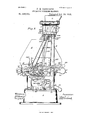
- Figure 1 is a partial front elevation of a weighing-machine of the class described constructed in accordance with my present invention and showing the machine broken in the center for the purpose of illustrating the same on a large scale, thereby clearly outlining the structure of the same.
- Fig. 2 is a vertical sectional plan view of the same, and also shows the machine broken in the center fora like purpose.
- Fig. 3 is an end elevation of the machine as seen from the right hand in Fig. 1, and shows the mechanism at one end of the machine, the several operative mechanisms being in their normal positions with the valveopen and delivering the material from the supply-chute into the bucket.
- Fig. 4 is an end elevation looking from the opposite end of the machine to that shown in Fig.
- Fig. 5 is an end elevation looking from the same end of the machine as in Fig. 3, the valve being shown in its drip position and the other operative mechanisms in the poising position of the machine, parts of the apparatus being removed to more clearly illustrate the construction and operation.
- Fig. 6 is an end elevation looking from the same end of the maebineas in Fig. 4, the valve being shown in the position it assumes at the moment of the cut-0B.
- Fig. 7 is an end elevation looking from the same end of the machineas in Fig. 3, the valve being shown in its closed position and the bucket-closer being wide open with the load discharging from the bucket, and those portions of the counterpoising mechanism and bucket which are illustrated being returned to their normal potions, parts of the apparatus being removed, also, to more clearly illustrate the operation.
- Fig. Si an end elevation looking from the same end of the machine as in Fig.
- FIG. 9 is a detail plan view corresponding to a portion of the lefthand end of the machine shown in Fig. 2, and illustrating a slight modification which will be hereinafter described.
- the framework for carrying the operative parts of the machine may be of any suitable construction, and is shown in the drawings as comprising two side frames or uprights 2 and 4, mounted upon a chambered supporting base 3 and connected by a top plate 5, to which a suitable hopper, such as H, is shown secured by means of some holding device, such as fastoning-bolts.
- the side frames 2 and t are shown herein as carrying some suitable beam-supports or V-shaped bearings, such as 20 and 20', for su pporting the scalebeams which carry the bucket mechanism, consisting of the bucket and its operative devices.
- a pair of oppositelydisposed counterweighted beams are shown at B and B, respectively, as pivotally mounted on beam-supportsas, for instance, by means of the pair of pivots or knife-edges E24 and the oppositely-disposed pair of pivots or knifeedges 2t-and as having bucket-supports l cated intermediate of said beam-supports and adjacent to the corresponding beam-supports, these bucket -supports being shown in the drawings as comprising two remotely-disposed pairs of pivots 0r knifeedges 1-5 and 15' and 17 and 17.
- Each of the scale-beams B and B is shown herein as having a pair of beam-arms joined by a combined connecting-shaft and counterpoise, the counterpoise for the beam 1 being designated by ⁇ V and that for the beam 13 being designated by W.
- Each of the scalebeams therefore, as is usual, has a bucketpoising portion and a bucket-counterpoising portion.
- Each of the beam-arms comprises a bucketpoising and bucket-counterpoisiug member or end, the bncket-counterpoising portiouscf the beam-arms for the scale-beam B being designated herein by 28 and 28, re spectively, and the bucket-counterpoising portions of the oppositely-disposed arms of the beam B being designated by :29 and 2' respectively.
- bucket-supports 15 and 15' and 17 and 17' are shown in the drawings as carried on the corresponding beam-arms of the two scale-beams B and B.
- each of said links is shown herein as having oppositelyconcaved supports or bearing-faces-such, for instance, as the jou rnal-openings 553 and 553', for engaging oppositely-disposed pivots or knifeedges 5-54 and 554'.
- knife-edges 554 and 55* are also illustrated herein as forming integral parts of 01 positely and transversely disposed members projecting from said inner ends of said beam arms and having journal portions, substantially filling the corresponding journal-openings in the link, along one of the diameters of said opening.
- the bucket or load-carrying receptacle which is of the single-chambered type or clas, is shown herein as having a relatively-wide central portion and relatively-narrow receiving and discharging openings and as substantially symmetrical at opposite sides of a central horizontal plane passing therethrough, so that the major portion of the load flowing thereinto will be sustained adjacent to and below said horizontal plane of the bucket, to thereby lower the center of gravity of the receptacle when loaded to its normal capacity.
- the bucket or load-carrying receptacle is pivotally mounted on the oppositely-disposed scale-beams, and is shown herein as having bearing-faces, such as 16, in position for engaging the bucket-supports carried by the scale-beams.
- bearing-faces such as 16
- each of these bearing-faces is substantially V-shaped, and said bearing-faces correspond in number and position with the knife-edges 15 and 15' and 17 and 17.
- the bearing-faces 16 are shown as equidistantly disposed from the center of the receptacle, it being understood that the bucket should be so constructed as to have no tendency to preponderate in either the one direction or the other, and that the center of gravity of said bucket is substantially in the central vertical plane thereof.
- the bearing-faces 16 may be carried by the bucket in any suitable manner, and are illustrated in the drawings as supported by brackets or hangers 555, rigidly secured to the ends of the bucket.
- the bucket-closer which is designated in a general way by L, is shown as consisting of a suitably-formed plate or closer proper,such as 75, having a counterweighted arm 79,preferably formed integral therewith, the closer being also illustrated as pivoted at 77 and 78 to the lower side of the bucket and adjacent to one side of the discharge-opening thereof.
- the closer-plate is preferably formed so as to hold the material being weighed without closing against the edges of the walls of such bucket-discharge opening, but closes under these edges and contiguous to a guard, such as 36, which is secured to the lower side of the bucket in such a position that the con tents of the bucket are kept from leaking out without requiring a very close fitting of the parts.
- an inverted toggle connection is shown in the drawings as connecting the closer and the bucket, and this toggle connection is so positioned as to be engaged by a closer-latch and held at about the angle of repose of the connection when the latch is in its operative position and the closer is shut.
- this toggle connection comprises some suitable rocker-such, for instance, as 550-pivoted on the end of the bucket and having a connecting rod or link 556 pivoted to said rocker, and also pivoted to the closer in such a manner that when the closer is shut the two pivots of said connectingrod or toggle member will be nearly in line with and the upper of said pivots will be above the rocker-pivot, whereby when the rocker is engaged by the latch and held in that position the closer will be supported with a minimum pressure on the latch, as practically all of the weight of the bucket contents will be carried on the pivot 550" of the rocker.
- suitable rocker such, for instance, as 550-pivoted on the end of the bucket and having a connecting rod or link 556 pivoted to said rocker, and also pivoted to the closer in such a manner that when the closer is shut the two pivots of said connectingrod or toggle member will be nearly in line with and the upper of said pivots will be above the rocker-pivot, whereby when the rocker is engaged
- the closer-latch for locking the rocker in position when the closer is shut is shown herein as pivoted at 87 on the end of the bucket and as having a detent or stop 81 in position and adapted for engaging a co-operating stop on the toggle connection when the parts are in the closed position previously described.
- This cooperating stop of the toggle connection is illustrated at 550 as carried on the rocker 550 and as substantially vertically superposed relatively to the pivot 550" when the closer is shot. It will be understood, of course, that that end of the latch which engages the cooperating stop of the toggle connection is suitably weighted, so as to tend to normally engage snch toggle-connection stop.
- the rocker 550 is shown as having a curved face, preferably de-. fined by an arc struck from the pivot 550" as a center and against which curved face said detent end of the latch is adapted to normally engage.
- the bucket has two members, one of which is shiftable relatively to the otherfor discharging the load, and that the bucket: closer in the present case constitutes.
- the shiftable bucket-discharge member and has a bucket-discharge movement controlled, by the bucket-closer latch.
- Such a stop is shown at 88 as carried on the scale-beam B, and the closerlatch is also shownas having a stop in position for co-operating with the stop on the scalebeam and adapted to be engaged to release the latch at a predetermined point in the descent of the bucket and the beam, owing to the relatively-rapid movement of the beam-stop as compared with the movement of the stop on the closer-latch.
- one of the latch-releasing stops should have a relative movement out of the path of the other, in order that the closerlatch may remain operative to hold the bucket-closer against opening.
- the stop on the bucketcloser latch as so movable and as comprising a swinging arm 557, pivoted at 557' to the latch and as having means for normally maintaining such stop in its operative position.
- the means which is shown herein for obtaining this result is a spring, such as 557", secured to the closer-latch on that side of the latch-pivot which is opposite the counterweighted end of the latch, and the free end of this spring is shown as engaging the stoparm 557 to normally hold the same in the path of movement of the stop 88.
- valve substantially similar to that shown in my Patent No. 535,727, granted March 12, 1895. I have shown such a valve at 70, pivoted within arms or' b.rackets 5', depending from the top plate of the machine, the pivot or axis of movement of the valve being designated by The valve employed is also illustrated as located substantially beneath the mouth of the supply-chute and as extending beyond the forward edge of said chute sufficiently far to support the descending column or stream when the valve is closed, and the valve is also or may be counterweighted at its rear end, as at 90, so, as to have a normal self-closing tendency.
- this counterweight is shown as constituting a valve-closing actuator, or means for actuating the valve to close the same; but I do not limit myself to the use of any particular means for effecting such closing movement.
- my said Patent No. 535,729 first hereinbefore referred to, I have shown and described means for limiting or intercepting the opening movement of the valve while the closer is open, and for also limiting or intercepting the opening movement of the closer while the valve is open, in connection with means for actuating the valve to open and close the same, independently of the operation of the bucket-closer, and in the present application I have retained this feature of a reciprocal control or mutual dependeneyof the opening movements of the valve and the closer in an improved embodiment of the means for obtaining this result, whereby the controlling action is rendered more perfectly sensitive.
- the rocker 550 is shown herein as having pivotally connected thereto at 417 a valvestop or valve-stopping thrust member 415, and this stop or stop-arm is shown connected to the rocker in such aposition that said stop will have a relatively-rapid movement (illustrated herein as an upward-thrust movement) on and with respect to the opening movement of the bucket-closer, so that the frictionroller 413, which I have shown as constituting the stop proper, will have an accelerated thrust movement for. intercepting the valve during the initial opening movement of the bucket-closer. In the absence of the frictionroller the end of the rod will, of course, constitute such stop.
- the valve is shown as also having a stop 412, provided with connected stop-faces 412' and 412" in position and adapted to be engaged by'the closer-operated valve-stop on the opening movement of the closer, the stop-face 412' being positioned relatively to the said closer operated stop, so that such stop-face will be eifective to limit or check the opening movement of the valve when the closer is released during the period while the valve is closed, the other stop-face 412" being positioned relativel y to the said closer-operated stop, so that such stop-face will act as a safety device to limit or prevent opening movement of the valve while the closer is open by limiting or checking the opening movement of the closer, if the closer-latch is released, during the period while the valve is actually open.
- the closer-supporting means modify the movements of the valve-stop or valve-stopping thrust member relatively to the opening movementof the closer, and that this modification is in the nature of an acceleration of the movement of such closer-operated stop or valve-stopping thrust member.
- the valve mechanism and the bucket-closer have two eoacting stops, one of which is operative with the closer and the other of which is operative with the valve mechanism, and that these stops are so positioned that they reciprocally limit the move ments of and serve as stop devices for each other, and that one of said stops, and preferably that operative with the closer, has a elatively rapid movement, preferably a thrust, on and with respect to the opening movement of the bucketcloser.
- this relatively rapid movement of the valve'stopping member is, as hereinbefore stated, eliected by the closer-supporting means.
- the closer-supporting means not only holds the closer against the pressure of the contents of the bucket, but also serves to actuate the valve-stop connected therewith, so as to project said stop into the path of the valve, and therebylimit the movement of said valve.
- the stop-arm 415 is illustrated as having a connecting link or rod 414', pivotally secured thereto at the point where the friction-roller 413 is located, and having said connecting-rod also pivotally secured to the framework at 414, so that the rod constitutes a thrusttransmitting member for relieving the stop-arm 415 of the thrust of the valve and directing said thrust against a thrust-receiving member, which, as just described, constitutes a portion of the fixed framing.
- valve 70 is shown in the drawings as having aconnecting rod or arm 55S pivotally secured to the upper rear portion thereof and as having the lower end of said rod in position and adapted to be engaged by a valveopening actuator, which will now be described, said connecting-rod 558 being also shown as having a pivotal connection, by means of a guide-link 559, with a relatively fixed portion of the machine, (herein shown as the framework adjacent to the rear of said machine.)
- the connecting-rod 558 is illustrated as constituting the means for transmitting to the valve the valve-opening movement of a valve'actuator, and that valve-actuator which has for its function the operation of opening the valve to permit the flow of the supply-stream into the bucket is shown herein as pivotally mounted on one of the scalebeams, in the present instance the beam B.
- this valve-opening actuator consists of a lever 551, pivoted at 551' to the scale-beam B and counterweighted at its rear end.
- This actuator or counterweighted lever which is shown as constituting and will also be hereinafter referred toasasupplemental counterpoise or suppletnental balancing means, normally forms part of the bucket-counterpoising portion of the scale-beam B and therefore of the whole bucket-counterpoising mechanism, but is automaticallyshiftable onto the bucket-poising mechanism at a predetermined point in the movement, herein shown as the ascent of the bucket.
- this valve-opening actuator or supplemental balancing means as a portion of the counterpoise of the beam B
- said beam is shown herein as having a stop 560, on which the said balancing means is normally supported.
- the lever 551 serves for one. of the purposes of the machine as a valve-opening actuatorand for another of the requirements of the machine it constitutes supplemental balancing means or a supplemental counterpoise.
- the pivot 551" of the valve-opening actuator is shown located between the bucket-supports which are carried by the scale-beams so that any downward pressure exerted upon the inner end of the actuatinglever 551 relatively to the bucket will oscillate the supplemental balancing means and that a very slight oscillatory movement will shift the same from the counterpoising mechanism of the machine onto the poising mechanism thereof, and thereby not only add tothe poising side of the beam a relatively considerable weight, but also subtract-from. the counterpoisi-ng side of the beam the same or substantially the same amount of weight.
- the connecting-rod 558 has been hereiubefore described as having its lower end in position and adapted to be engaged by a valveopening actuator, and hence it will be evident that the lever 551 constitutes the means for engaging said rod.
- this rod 558 forms part of the actuating means and therefore a part of the valve-opening actuator; but when the opening movement of the valve is prevented it will also be evident that this rod forms astop device for limiting or checking the valveopening movement of the valve-actuator.
- connecting-rod 558 and the scalebeam B form shifting means for engaging the supplemental balancing means and automatically shifting the same from the counterpoising to the poising side of the mechanism ata predetermined point in the movement of the bucket.
- valve-opening movement of the valve-opening actuator be prevented during that period in which the load in the bucket is being made up, it will be evident that if the valve-opening-movement limiter is in its operative position it will be impossible for the valve-opening actuator to be effective as such, as the rod 558 will engage said actuator and form a stop device for limiting or checking the valve-opening movement thereof; also, that when not supported on the stop 560 and when not checked by the stop device controlled by the closing movement of the valve said valve'opening actuator will be operable as such.
- valve mechanism in a weighing-machine as ordinarily constructed is that in which the full flow of the supply-stream into the bucket is permitted; and hence the actuator for opening the valve is shown herein as of relatively-greater power or efficiency than the means for closing said valve.
- the valve-opening actuator is also illustrated in the present case as operativein opposition to the valve-closing means and therefore in opposition to the closing movement of the valve.
- valve-opening actuator For the purpose ofpreventing the closing movement of the valve during that period in which the valve-opening actuator would ordinarily be efiective it will be obvious that in a machine such as described, having a valve-opening actuator operative in opposition to and of relatively greater power or eliiciency than the means for closing the valve, a stop device located intermediate of the valve-opening actuator and the valve-closing means and forming an intermittently-fixed connection between the valveclosing means and the valve-opening actuator will be sufficient while in such fixed position to hold the valve against any closing movement that can be exerted by the normal operation of the valve-closing means.
- the connecting-rod 55S therefore constitutes not only a stop device for checking the valveopening movement of the valve-opening actuator during the period in which the valveopening-movement limiter is in its operative position, but also astop device for preventing the closing movement of the valve during the period beginning with the release of the valve-opening-movement limiter and ending with the commencement of the descent of the bucket and the scale-beams, it being apparent, of course, that the valve-opening movement of the valve-openingactuator is checked during the descent of the bucket and the beams, the stop 560 having been already described as provided for this purpose.
- valve has its closingmovcment during the period in which the closer-openingmovement limiter is in its operative position
- the valve-opening actuator has its valve-opening movement alternating with the closing movement of the valve, and hence the valve-opening and valve closing actuators are alternately elfective.
- the connecting-rod 558 or some suitable means for limiting the closing movement of the valve and the valveopening movement of the valve-opening'actuator, and hence for limiting the valve-actuating movements of the valve-opening and val ve-closing actuators I term a valve-movement stop; and it will be seen that such a valve-movement stop is adapted for reciprocally limiting the closing movement of the valve and the valve-opening movement of the valve-opening actuator, and is therefore adapted for reciprocally limiting the valveactuating movements of the valve-opening and valve-closing actuators, so that it will be impossible for the valve-closing movement to take place or for the valve-actuating movement of the valve-closing actuator to occur while the valve-opening actuator is operative as such.
- valve-movement stop has been described as being connected with the valve and as movable relatively to the valve-opening actuator at the lower end of said stop, I do not limit myself to such a construction, but consider as within the scope of my invention any means operated as a valve-movement stop, positioned and adapted to have the functions here stated.
- the valve As a means for controlling the drip-stream, the valve isshown provided with a stop, and a detent is so positioned and adapted as to engage this stop and hold the valve against closing during the drip period.
- valve-stop for this purpose is shown at 418, and a detent device adapted for engaging this valve-stop is shown as comprising a counterweighted lever 420, pivotally mounted at 420" on the framework of the machine and pivotally secured to a connecting-rod 420', carrying a stop member or detent proper 419, adjacent to the stop 418 and in position and adapted for engaging this last-mentioned stop during the drip period.
- a guidelink or thrust-receiving member is'shown at 419 as preferably pivoted at the point 414 to the frame of the machine, this pivotal point being that also, as before described, of tho guide-link414'.
- the detent for engaging the valve-stop is therefore a swinging one and engages the valvestop at a predetermined point in the movement of the valve, and the detent is also shown as having a stop 419" in position for engagement by one of the scale-beams on the descent ofsaid beam toa predetermined point, whereupon the detent will be carried out of the path of movement of the co-operating valve-stop.
- any suitable stop device such as that shown at 422, may be employed.
- a scale-arm is shown herein at 501 as carried by and movable with one of the scalebeams, in this instance the scale-beam B, and as adapted to carry a load-weight, which is adapted to be slid from the po'ising to the counterpoising side of the scale-arm, and vice versa, to thereby simultaneously reduce the weight of one of the balancing mechanisms and increase the weight of the other.
- a loadweight adapted for this purpose is shown at M, carried on the scale-arm 561, and as slidable thereon from end to end of the same. This load-weight is shown in Fig.
- the scale-arm 561 is also shown in the drawings as provided with a scale, having a series of division-lines 561 extending transversely across one face of said scale-armvto indicate any required graduations.
- the load-weight is also illustrated in the present instance as having a scale-face, such as 564, in parallelism with a diagonal line connecting the corresponding opposite terminals of two adjacent division-lines on the scale-arm, and said scale-face is furnished with a Vernier-scale 564', coinciding in length with this diagonal, the vernier or cross scale being graduated to represent any usual subdivisions of the unit indicated by the grad uations on the scale-arm.
- the main and Vernier scales permit the operator to ascertain the weight of a partial load, such as usually remains at the end of a predetermined period of operation of the machine, as when weighing from a bin, the material thus left in the bin being usually less than a full load.
- a partial load such as usually remains at the end of a predetermined period of operation of the machine, as when weighing from a bin, the material thus left in the bin being usually less than a full load.
- valve With the parts in position shown in Figs. 3 and 4 (the normal position for the commences ment of the weighing operation) the valve is wide open and permits the uninterrupted flow of the stream issuing from the supplychute Hdown into the bucket G. At this time the bucket-latch 82 is operative to. hold the closer L shut, and hence thevalve-openingmovement limiter lies below and out of en-.
- valveopening actuator falling slowly from under the valve-movement stop, permits the valveopening movement to begin, and at the same time the stop-face412" is shifted relatively to the valve-opening-movement limiter until the detent-stop 419 engages the stop 418, carried by the valve, when said valve-opening-movement limiter will be at the extreme end of said stop-face 412" and in position to engage the stop-face 412 on the release of thedetent419, as shown in Fig. 5.
- the detent-releasing stop carried by the scale-beam B is also shown as about to carry down the stop 419".
- valve-movement stop rises from the valve-opening actuator, owing to the continuation of the descent of the beams, and on the release of the detent by the beam-stop or other detaching means the valve is quickly carried to the cut-off position shown in Fig. 6 and the valve-movement stop (which at the moment of the release of the detent was some distance above the valve-opening actuator) is thrown quickly or actuator shown at 551.
- valve-movement stop thus serving as a power-transmitting means, and an added impetus, due to the weight, momentum, and impact of said valve-operated means, is given to the bucket-poising mechanism to carry the same rapidly to the limit of the descending movement and thereby insure the release of the bucket-closer latch.
- Fig. 7 the bucket-closer latch is shown as having been released from engagement with the stop 550 on the toggle connection, owing to the actuation of the stop 557 by the stop 88,
- valve-movement stop 558 is a rigid abutment by reason of the valve-openingv the normal position; but if, as might be the case in small-sized machines, the main counterpoise mechanism constitutes the valveopening actuator, then the whole balancing mechanism will of course be held against return movement.
- the only change involved would be the substitution of a properly-positioned stop-face on the beam mechanism for the supplemental balancing means
- Fig. 9 in which the roll 551" is shown carried by a pin 551', fixed directly in the beam-arm 10'.
- valveopening actuator will be held inoperative as such by the valve-movement stop until the closer is entirely shut, as the valve-opening-movement limiter is not released from itsengagement with the valve until the last part of this closer movement.
- the bucket-closer latch 82 will re- .engage the closer-supporting means and at the same moment, owing to the withdrawal of the valve-opening-movement limiter 415 on its return-stroke, the valveopening actuator 551 becomes operable for reverse oscillatory movements, and, returning to its normal position, forces the valve open, and the valvemovement stop 558 is then operative to prevent the closing of the valve until the b ginning of a new cycle of movements, the cioseropening-movement limiter 412 beingreturned at the same time to its efiective position.
- valveopening actuator is held ineffective by the valve-opening-movement limiter during the efiective action of said limiter, and hence has an inetfective period synchronous with the effective period of this limiter, and the valveclosing actuator is operable with the closeropening-movementlimiter and by the descent of the scale-beam and is elfective alternately with the valve-opening actuator.
- valve-opening actuator oscillatory on and relatively to one of the scale-beams the operation of said actuator is rendered very sensitive, as on its release by the valve-movement stop (which, as will be seen. is releasable in turn on the return stroke of the valve-opening-movement limiter,) a relatively-small resistance is opposed to the action of such valveopening actuator. It will be noticed, also, that while the valve-opening actuator is operable on one release of the valve-movement 7 stop the valve-closing actuator is operable on the other release of said stop, so that the two actuators are mutually dependent and are resistively connected.
- I claim- 1 In a weighing-machine, the combination with a valve and with a bucket-closer; of reciprocally-effective, valve-opening-movement and closer-opening-movement limiters; and a valve-opening actuator, operable on the return stroke of the valve-opening-movement limiter, and having an ineifective period synch ronous with the eifective period of said limiter, substantially as described, and for the purposes set forth.
- a weighing-machine the combination with a valve and with a bucket-closer; of reciprocally-effective, valve-opening-movement and closer-opening-movement limiters; and a valve-opening actuator, held ineffective by the valve-opening-movement limiter during the effective action of said limiter, and operable on the return stroke of said limiter, substantially as described, and for the purposes set forth.
- a valve having its closing movement during the period in which the closer-openingmovement limiter is in its operative position; and with a bucket-closer; of reciprocallyeifective, valve-openingmovement and closeropening-movement limiters; and a valveopening actuator operable on the return stroke of the valve-opening-movement limiter, and having its valve-opening movement alternating viththe closing movement of said valve, substantially as described,and for the purposes set forth.
- a weighing-machine the combination with a valve and with a bucket-closer; and with reciprocally-eifective, valve-opening movement and closer-opening-movement limiters; of alternately-efiective valve-opening and valve-closing actuators, having the former operable on the return stroke of the valveopening-movement limiter, and the latter operable with the closer-opening-movement limiter, substantially as described, and for the purposes set forth.
- a weighing-machine the combination with a valve, a scale-beam and a bucket-closer; and with reciprocally-efiective, valve-opening-movement and closer-opening-movement limiters; of altern'ately-eifective valve-opening and valveclosing actuators, having the former operable on the return stroke of the valve-opouing-movement limiter,and the latter operable with the closer-opening-movement limiter, and by the descent of the scalebeam, substantially as described,and for the purposes set forth.
- a weighing-machine the combination with a valve and with a bucket-closer; and with reciprocally-eifeotive, valve-openingmovement and closer'opening-movement limiters; of alternately-effective and mutuallydependent valve-opening and valve-closing actuators, operative in opposition to each other, and having the former operable on the return stroke of the valvc-opening-movement limiter, and the latter operable with the closer-opening-movement limiter, substantially as described, and for the purposes set forth.
- a weighing-machine the combination with a valve, a scalebeam, and a bucketcloser; of reciprocally-effective, valve-opening-movement and closer-opening-movement limiters; a valve-closing actuator operable with the closer-opening-movernent limiter; and a valve-opening, actuator effective alternately with the valve-closing actuator, and carried by the scale-beam, and operable on the return stroke of the valve-openiug-movement limiter, and having its valve-opening movement relatively to said scale-beam,sub-- stantially as described, and for the purposes set forth.
- a weighing-machine the combination with a valve, a soalebeam and a bucketcloser; of reciprocally-etfective, valve-opening-movement and closer-opening-moveinent limiters; a valve-closing actuator operable with the closer-opening-movement limiter and by the descent of the scale-beam; and a valveopening actuator effective alternately with the valve-closing actuator, and carried by the scale-beam, and operable on the return stroke of the valve-opening-movement limiter, and having its valve-opening movement relatively to said scale-beam, substantially as described, and for the purposes set forth.
- a weighing-machine the combination witha valve; and with a shiftable bucket-dis charge member having a bucket-discharge movement; of a limiter for the bucket-discharge movement of said bucket-discharge member; a valve-opening-movcment limiter reciprocally etfective with said bucket-dis charge-movement limiter; and a valve-opening actuator operable on the return stroke of the valve-'opening-movement limiter, and having an ineffective period synchronous with the effective period of said limiter, substantially as described, and for the purposes set forth.
- a weighing-machine the combination with a valve,a counterpoised scale-beam and a bucket-closer; 0t reciprocallyeffective, valve-opening-movement and closer-opening; movement limiters; a valve-closing actuator operable with the closer-opening-movement limiter, and by the descent of the scale-beam; a valve-opening actuator efiective alternately with the valve-closing actuator, and carried by the scale-beam, and normally forming part of the counterpoise for said beam, and operable on the return stroke of the valve-opening-movement limiter, and having its valveopening-movement relatively to said scale beam; and a stop on the scale-beam, and in position and adapted for normally preventing relative movement of the valve-opeuing actuator with respect to the scale-beam, snb
- a weighing-machine the combination with a valve, a counterpoised scale-beam and a bucket -closer; of reciprocaily effective, valveopeningmovement and closer-openi ngmovement limiters; a valve-closing actuator operable with the closer-opening-movement limiter, and by the descent of the scale-beam; a valve-opening actuator effective alternately with the valve-closing actuator, and pivotall y mounted on the scale-beam, and normally forming part of the cou nterpoise forsaid beam, and operable on the return stroke of the valveopening-movement limiter, and having an oscillatory valve-opening movement relatively to said scale-beam; and a stop on the scale beam, and in position and adapted for normally preventing oscillatory movement of the valve-opening actuator relativei y to the scalebeam, substantially as described, and for the purposes set forth.
- a weighing-machine the combination with a valve, a scale-beam and a bucket-closer; of reciprocally-etfective, valve-openiug-movement and closer-opening-movemeut limiters; a valve-closing actuator operable with the closer-openingmovement li miter; and a val veopening actuator efiective alternately with, and of relatively-greater efiiciency than, the valve-closing actuator, and carried by the scale-beam, and operable on the return stroke of the valve-opening-movement limiter, and havingits valve-opening-movement relatively to said scale-beam, substantially as described, and for the purposes set forth.
- a weighing-machine the combination with a valve, a scale-beam and a bucket-closer; of reciprocally-etfective, valve-opening-movement and closer-opening-movement limiters; a valve-closing actuator operable with the closer-opening-movement limiter, and by the descent of the scale-beam; and a valve-opening actuator effective alternately with, and of relatively-greater efiiciency than, the valveclosing actuator, and operative in opposition to said valve-closing actuator, and carried by the scalebearn, and operable on the return stroke of the valveopening-movement limiter, and having its valve-openingmovement relatively to said scale-beam, and operable to its valve-opening position and relatively to the scale-beam by the ascent of said beam, substantially as described, and for the purposes set forth.
- a weighing-machine the combination with a valve and with a bucket-closer; of reci procally-etfective, valve-opening-movement and closer-openingmovement limiters; a valve-opening actuator operable on its release by the valve-movement stop, and having an inefiective period synchronous with the effective period of the valve-opening-movemeut limiter; a valve-closing actuator effective alternately with the valve-opening actuator, and operable with the closeropening-movement limiter; and a valve-movement stop for the valve-opening actuator, and releasable on the return stroke of the valveopening-movoment limiter, and in position and adapted for engaging the valve-opening actuator during the period beginning with the final closing of the valve and ending with the subsequent release of the valve by the valve-opening-movement limiter, substantially as described, and for the purposes set forth.
- valve-opening actuator operable with the closeropeningmovement limiter, and by the descent of the scale-beam; a valve-opening actuator efiective alternately with, and of relatively-greater efficiency than, the valveclosing actuator, and operative in opposition tosaid valve-closing actuator, and carried by the scale-beam, and operable on its release by the valve-movement stop, and having its valve-opening movement relatively to said scale-beam; and a valve-movement stop for the valve-opening actuator, and releasable on the return stroke of the valve-opening-movement limiter, and in position and adapted for engaging the valve-opening actuator during the period beginning with the final closing of the valve and ending with the subsequent release of the valve by the valve-opening-movement limit
- a valveand with abucketcloser the combination with a valveand with abucketcloser; of reciprocallyetfective, .valve opening movement and closer-opening-movement limiters; a valve-opening actuator operable on its release by the valve-movement stop, and having an inelfective period synchronous with the eifective period of the valve-opening-movement limiter; a valve-closing actuator eifective alternately with the valve-opening actuator, and operable with the closer-openingmovement limiter, and a valve-movement stop for the valve-opening actuator, and releasable on the return stroke of the valveopening-movement limiter, and in position and adapted for engaging the valve opening actuator during the period in which said limiter is in its operative position and preventing the valve-opening movement of the valve-opening actuator during said period, and for holding said valve-opening actuator in its valve'opening position relatively to the scalebeam on the ascent of said beam,
- a weighing-machine the combination with a valve and with a bucket-closer; of reciprocally efiective, valve openingmovement and closer-openingmovement limiters; a valve-opening actuator operable on its re lease by the valve-movement stop, and having an inefiective period synchronous with the effective period of the valve-opening-movement limiter; a valve-closing actuator elfective alternately with the valve-opening actuator, and operable with the closer-opening movement limiter; and a valve-movement stop for the valve-opening actuator, and releasable on the return stroke of the valveopening-movement limiter, and carried by the valve, and in position and adapted for engaging the valve-opening actuator during the period beginning with the final closing of the valve and ending with the subsequent release of the valve by the valve-opening-movement limiter, substantially as described, and for the purposes set forth. 4
- valve-opening actuator operable on its release by the valve-movement stop, and having an inefiective period synchronous with the etfective period of the valve-opening-movement limiter; a valve-closing actuator etIective alternately with the valve-opening actu ator, and operable with the closer-opening- Inovement limiter; and a valve-movement stop for the valve-opening actuator, and releasable on the return stroke of the valveopening-movement limiter, and pivotally secured to the valve, and in position and adapted for engaging the valve-opening actuator during the period beginning with the final closing of the valve and ending with the subsequent release of the valve by the valveopening-movement limiter, substantially as described, and for the purposes set forth.
- a weighing-machine the combination with a valve and with a bucket-closer; of reciprocally-etfective, valve-opening-movement and closer-openingmovement limiters; a valve-opening actuator operable on its release by the valve-movement stop, and having an ineifective period synchronous with the eflfective period of the valve-opening-movement limiter; a valve-closing actuator effective alternately with the valve-opening actuator, and operable with the closer-openingmovement limiter; and a valve-movement stop for the valve-opening actuator, and releasable on the return stroke of the valveopening-movement limiter, and pivotally secured to the valve, and having a swinginggnide pivoted to said valve-movement stop and to a fixed portion of the machine, and in position for engaging the valve-movement stop with the valve-opening actuator during the period beginning with the final closing of the valve and ending with the subsequent release of the valve by the valve-opening
- valve-opening actuator operable on its release by the valve-movement stop, and having an inetfective period synchronous with the effective period of the valve-opening-movement limiter; a valve-closing actuator effective alternately with the valve-opening actuator, and operable with the closer-openingmovement limiter; and a valve-movement stop for the valve-opening actuator, and releasable on the return stroke of the valve-openingmovement limiter, and fixed relatively to one of the valve-operating actuators, and in position and adapted for engaging the other of said valve-operating actuators during the period beginning with the final closing of the valve and ending with the subsequent release of the valve by the valve-opening-inovement limiter and preventing the valve-opening movement of said valve-opening actuator,
- valve movement limiter is in its operative position; and with a bucket-closer; of reciprocally-effective, valve-opening-movement and closeropening-movement limiters; a valve-opening actuator operable on the return stroke of the valve-opening-movement limiter, and having its valve actuating movement alternating with the closing movement of said valve; and a valve-movement stop in position and adapted for limiting the valve-actuating movement of the valve-opening actuator throughout the period beginning with the final closing of the valve and ending with the subsequent release of the valve by the valve-opening-movement limiter, snbstantiallyas described, and for the purposes set forth.
- a valve having its closing movement during the period in which the limiter for the bucket-discharge movement of the bucketdischarge member is in its operative position; and with a shiftable bucket-discharge member having a bucket-discharge movement; of a limiter for the bucket-discharge movement of said bucket-discharge member; a valveopening-movement limiter reciprocally effective with said bucket-dischargemovement limiter; a valve-opening actuator operable on the return stroke of the valve-opening-movemeut limiter; and a valve-movement stop in position and adapted for reciprocallylimiting the closing movement of the valve and the valveopening movement of the valve-actuator, substantially as described, and for the purposes set forth.
- a weighing-machine embodying a scale-beam
- the combination with a valve having its closing movement during the period in which the closer-opening-movement limiter is in its operative position; and with a bucketcloser; of reciprocally-effective, valve-opening-movement and closer-opening-movementlimiters; a valve-opening actuator operable on the return stroke of the valve-openingmovement limiter, and having its valve-opening movement alternating with the closing movement of said valve; a stop carried by the valve; a detent in position and adapted for engaging said valve-stop and holding the valve against closure during the drip period; and means controlled by the overpoise movement of the scale-beam for releasing said detent and permitting the cut-off movement of the valve, substantially as described, and for the purposes set forth.
- a weighing-machine the combination with a valve, a scale-beam and a bucket-closer; of reciprocally-effective, valve-opening-movement and closer-opening-moveinent limiters; a valveclosing actuator operable with the closer opening movement limiter; a valveopening actuator efiective alternately with the valve-closing actuator, andcarried by the scale-beam, and operable on the return stroke of the valve-opening-movement limiter, and having its valve-opening movement relatively to said scale-beam; astop carried by the valve; a detent in position and adapted for engaging said valve-stop and holding the valve against closure during the drip period; and means controlled by the overpoise movement of the scale-beam for releasing said detent and permitting the cut-oif movement of the valve, substantially as described, and forthe purposes set forth.
Landscapes
- Physics & Mathematics (AREA)
- General Physics & Mathematics (AREA)
- Load-Engaging Elements For Cranes (AREA)
Description
8 Sheets-Sheet I.
F. H. RICHARDS. AUTOMATIC WBIGHING MACHINE.
(No Model.)
Patented Oct. 29, 1895.
Invent:
Ammtw LGIAIMM. "0104mm. WASMIG'WIJI C (No Model.) 4 8'Sheets-Sheet a H. RICHARDS. AUTOMATIC WEIGHING MACHINE.
No. 548,889. Patented oct'. 29, 1895.
Inventor:
. witnels'w;
AN DREW I GRANAN.H10TOWO.WASNING1D-.BC
(No Model.) 8 Sheets-Sheet 3.
P. H. RICHARDS. AUTOMATIC WEIGHING MACHINE.
No. 548,839. Iigtented Oct. 29, 1895.
l Wiflesses:
ANDREW B GRAHAMINGYO'UWQWASNIFGTOND C (No Model.) 8 Sheets-Sheet 4.
P. H. RICHARDS. AUTOMATIC WEIGHING MACHINE.
Nd. 548,839. Patented Oct. 29, 1895.-
Witnesses:
cumd a Annntw I GIANAPLPNOYO-UIIQWASNIIGWKOC.
i Inventor:
8 Sheets-Sheet 5.
(No Model.)
P. H. RICHARDS. AUTOMATIC WEIGHING MACHINE.
No. 548,839. Patented Oct. 29, 1895.
I72 ventor:
- W117i asses: xm
P. H. RICHARDS. AUTOMATIC WEIGHING MACHINE.
Patented Oct. 29, 1895.
Inventor:
I I I I With asses:
8 Sheets-Sheet (No Model.)
15'. H. RICHARDS.
AUTOMATIC WEIGHING MACHINE.
No. 548,839. Patented Oct. 29, 1895.
In 2/092 tor:
Wz tzzassas:
dy 9911a,.
'lllll Muinm I GmAHJNmUYnQWASINNGIDKQC.
UNITED STATES PATENT OFFICE.
FRANCIS H. RICHARDS, OF HARTFORD, CONNECTICUT.
AUTOMATIC WElGHlNG-MACHINE.
SPECIFICATION forming part of Letters Patent No. 548,839, dated October 29, 1895.
Application filed March 9, 1895.
To all whom it may concern.-
Be it known that I, FRANCIS H. RICHARDS, a citizen of the United States, residing at Hartford, in the county of Hartford and State of Connecticut, have invented certain new and usefullmprovements in Automatic Weighing-Machines, of which the following is aspecification. w
This invention relates to weighingmachines, and more especially to that class of weighingmachines which are adapted for antomatically and continuouslyweighing predetermined quantities of grain or other relatively free-flowing materials, the main object being to provide an etfective and accurate automatic weighing-machine of the singlebncket class in which all of the operations of loading and discharging the bucket and opening, closing, locking, and unlocking the valve and the bucket-closershall be performed by mechanisms comprising improved safety and actuating devices, whereby the operation of the valve mechanism and of the bucket mechanism shall be limited the one by the other, so as to prevent waste and insure the normal operation of the machine, and so as to prevent interference with that proper, predetermined, and necessary sequence of operations which is characteristic of the normal working of a perfectly-organized combination of mechanisms in a machine of this type.
Another object of the invention is to furnish the bucket or load-carrying receptacle of a machine of this class with a closer which shall control a relatively-large bucket-discharge opening as compared with the discharge-openings ot' buckets as heretofore constructed and which closer shall be supported when in its closed position by the application of a relatively-slight amount of force as compared with that required to maintain shut the closers of such prior-machines.
A further object of the invention is to provide reciprocally-eflfective limiters or stops operative, respectively, for controlling the opening movements of the valve and the bucket-closer, and which limiters shall be so organized that a relatively-slight opening movement of the bucket closer shall impart an accelerated or relatively-greater movement to the valve-opening-movement limiter to in- Serial No. 541,087. (No model.)
stantaneously limit or check the opening movement of the valve, and thereby prevent any material opening movement of the valve while the operative organization of the machine is maintained unless the closer is shut and locked in its shut position.
A further object of the invention is to furnish an improved bucketcarrying mechanism in which the bucket shall be supported by one ormore pairs of oppositely-disposed counterweighted beams having their movements in unison, and also to elfect the unlatching of the bucket-closer by means controlled by the relatively-rapid descending movement of the poising-arms of the scalebeams as compared with the descent of the bucket.
For the purpose of more perfectly and positively controlling the movements of the several operative parts of the machine the invention also contemplates the provision, in connection with the reciprocally-effective limiters or stops for preventing the opening of the closer when the valve is open, and vice versa, of an actuator for opening the valve, which actuator shall have its valve-opening movement positively controlled, so as to alternate with the closing movement of the valve, and which valve-opening actuator shall be inoperative as such except on the release of the valve by the opening-movement limiter or stop therefor, whereby such valveopening actuator shall be rendered ineffective as such throughout the major portion of the cycle of operations of the machine and without interfering with the proper working of the other operative mechanisms and devices.
An additional objectof the invention is to be found in the provision of means for automatically shifting a portion of the normal bucket-counterpoising mechanism onto the bucket poising mechanism at a predetermined point in the operation of the machine, and the controlling of one of the functions of the machine by one of the relative movements of such portion of the counterpoising mechanism with respect to the remainder of said counterpoising mechanism. In the present application the return movement of this relatively-movable portion of the counterpoise mechanism will hereinafter be described as operative for elTecting the opening of the valve.
Additional objects of my invention are to be found, also, in the provision of means for obtaining in one machine a very wide range of capacities and for setting the machine to weigh and to read any desired or resultant fractional part of a load.
As to one of the important features thereof, this invention is in the nature of an improvement upon that shown and described in United States Letters Patent No. 535,729, granted to me March 12, 1895, to which reference may be had; and as to other of the parts thereof many of those features of this machine which are not claimed or are of minor importance are to be found in other prior and concurrent applications for patents.
In the drawings accompanying and forming part of this specification, Figure 1 is a partial front elevation of a weighing-machine of the class described constructed in accordance with my present invention and showing the machine broken in the center for the purpose of illustrating the same on a large scale, thereby clearly outlining the structure of the same. Fig. 2 isa vertical sectional plan view of the same, and also shows the machine broken in the center fora like purpose. Fig. 3 is an end elevation of the machine as seen from the right hand in Fig. 1, and shows the mechanism at one end of the machine, the several operative mechanisms being in their normal positions with the valveopen and delivering the material from the supply-chute into the bucket. Fig. 4 is an end elevation looking from the opposite end of the machine to that shown in Fig. 3, and illustrating the mechanism at such end of the weighing-machine, the several operative mechanisms being in positions corresponding with those shown in F ig.3. Fig. 5 is an end elevation looking from the same end of the machine as in Fig. 3, the valve being shown in its drip position and the other operative mechanisms in the poising position of the machine, parts of the apparatus being removed to more clearly illustrate the construction and operation. Fig. 6 is an end elevation looking from the same end of the maebineas in Fig. 4, the valve being shown in the position it assumes at the moment of the cut-0B. and just prior to the opening of the bucket-closer, and the other operative mechanisms being in posi' tions corresponding with such position of the valve, certain of the parts of the apparatus also being removed to more clearly illustrate the construction and operation of the machine. Fig. 7 is an end elevation looking from the same end of the machineas in Fig. 3, the valve being shown in its closed position and the bucket-closer being wide open with the load discharging from the bucket, and those portions of the counterpoising mechanism and bucket which are illustrated being returned to their normal potions, parts of the apparatus being removed, also, to more clearly illustrate the operation. Fig. Sis an end elevation looking from the same end of the machine as in Fig. 4, the valve being closed and the closer open, but nearly closed, the bucket empty, and the valve-opening actuator, which will be hereinafter more particularly referred to, being in position for opening the valve upon the unlocking of the valve by the locking shut of the closer. Fig. 9 is a detail plan view corresponding to a portion of the lefthand end of the machine shown in Fig. 2, and illustrating a slight modification which will be hereinafter described.
Similar characters designate like parts in all of the figures.
The framework for carrying the operative parts of the machine may be of any suitable construction, and is shown in the drawings as comprising two side frames or uprights 2 and 4, mounted upon a chambered supporting base 3 and connected bya top plate 5, to which a suitable hopper,such as H, is shown secured by means of some holding device, such as fastoning-bolts.
The side frames 2 and t are shown herein as carrying some suitable beam-supports or V-shaped bearings, such as 20 and 20', for su pporting the scalebeams which carry the bucket mechanism, consisting of the bucket and its operative devices.
As a means for supporting the bucket or load-carrying receptacle a pair of oppositelydisposed counterweighted beams are shown at B and B, respectively, as pivotally mounted on beam-supportsas, for instance, by means of the pair of pivots or knife-edges E24 and the oppositely-disposed pair of pivots or knifeedges 2t-and as having bucket-supports l cated intermediate of said beam-supports and adjacent to the corresponding beam-supports, these bucket -supports being shown in the drawings as comprising two remotely-disposed pairs of pivots 0r knifeedges 1-5 and 15' and 17 and 17.
Each of the scale-beams B and B is shown herein as having a pair of beam-arms joined by a combined connecting-shaft and counterpoise, the counterpoise for the beam 1 being designated by \V and that for the beam 13 being designated by W. Each of the scalebeams, therefore, as is usual, has a bucketpoising portion and a bucket-counterpoising portion. Each of the beam-arms comprises a bucketpoising and bucket-counterpoisiug member or end, the bncket-counterpoising portiouscf the beam-arms for the scale-beam B being designated herein by 28 and 28, re spectively, and the bucket-counterpoising portions of the oppositely-disposed arms of the beam B being designated by :29 and 2' respectively.
For the purpose of supporting the bucket from and by the beam-arms the bucket- supports 15 and 15' and 17 and 17' are shown in the drawings as carried on the corresponding beam-arms of the two scale-beams B and B.
' Some suitable means for maintaining the movements of the scale-beams in unison, and hence the movements of the beam-arms in unison, will be employed, and I have shown such means herein as a guide connection between and joining the beams,and preferably comprising one or more connecting-linkssuch, for instance, as the links 552 and 552', connecting, respectively, the buckebpoising portions 19 and 21 and 19' and 21' of the scale-beams B and B. These bucket-poising portions of the scale-beams, it will be evident, com prise all those portion of said beams which lie between the supporting knife-edges 24: and 2t, by which the beams are sustained.
As a means for obtaining a free movement of each of the connecting-links relatively to the beam-arms which it joins, each of said links is shown herein as having oppositelyconcaved supports or bearing-faces-such, for instance, as the jou rnal-openings 553 and 553', for engaging oppositely-disposed pivots or knifeedges 5-54 and 554'. (Shown herein as carried by and on the inner ends of the bucket-poising portions of the beam-arms.) These knife- edges 554 and 55* are also illustrated herein as forming integral parts of 01 positely and transversely disposed members projecting from said inner ends of said beam arms and having journal portions, substantially filling the corresponding journal-openings in the link, along one of the diameters of said opening. -It will be evident that by providing an ordinary knit'eedge hearing or journal connection between the link and the beam-arms the friction between these parts will be reduced to a minimum, and that thereby freedom of movement of the beams will be promoted.
The bucket or load-carrying receptacle, which is of the single-chambered type or clas, is shown herein as having a relatively-wide central portion and relatively-narrow receiving and discharging openings and as substantially symmetrical at opposite sides of a central horizontal plane passing therethrough, so that the major portion of the load flowing thereinto will be sustained adjacent to and below said horizontal plane of the bucket, to thereby lower the center of gravity of the receptacle when loaded to its normal capacity.
The bucket or load-carrying receptacle is pivotally mounted on the oppositely-disposed scale-beams, and is shown herein as having bearing-faces, such as 16, in position for engaging the bucket-supports carried by the scale-beams. In the form thereof herein illustrated each of these bearing-faces is substantially V-shaped, and said bearing-faces correspond in number and position with the knife- edges 15 and 15' and 17 and 17. For the purpose of evenly balancing the bucket upon the beams the bearing-faces 16 are shown as equidistantly disposed from the center of the receptacle, it being understood that the bucket should be so constructed as to have no tendency to preponderate in either the one direction or the other, and that the center of gravity of said bucket is substantially in the central vertical plane thereof. The bearing-faces 16 may be carried by the bucket in any suitable manner, and are illustrated in the drawings as supported by brackets or hangers 555, rigidly secured to the ends of the bucket.
The bucket-closer, which is designated in a general way by L, is shown as consisting of a suitably-formed plate or closer proper,such as 75, having a counterweighted arm 79,preferably formed integral therewith, the closer being also illustrated as pivoted at 77 and 78 to the lower side of the bucket and adjacent to one side of the discharge-opening thereof. The closer-plate is preferably formed so as to hold the material being weighed without closing against the edges of the walls of such bucket-discharge opening, but closes under these edges and contiguous to a guard, such as 36, which is secured to the lower side of the bucket in such a position that the con tents of the bucket are kept from leaking out without requiring a very close fitting of the parts.
Asa meansforsupporting the bucket-closer, an inverted toggle connection is shown in the drawings as connecting the closer and the bucket, and this toggle connection is so positioned as to be engaged by a closer-latch and held at about the angle of repose of the connection when the latch is in its operative position and the closer is shut. In the form thereof herein illustrated this toggle connection comprises some suitable rocker-such, for instance, as 550-pivoted on the end of the bucket and having a connecting rod or link 556 pivoted to said rocker, and also pivoted to the closer in such a manner that when the closer is shut the two pivots of said connectingrod or toggle member will be nearly in line with and the upper of said pivots will be above the rocker-pivot, whereby when the rocker is engaged by the latch and held in that position the closer will be supported with a minimum pressure on the latch, as practically all of the weight of the bucket contents will be carried on the pivot 550" of the rocker.
The closer-latch for locking the rocker in position when the closer is shut, and which is designated by 8:3, is shown herein as pivoted at 87 on the end of the bucket and as having a detent or stop 81 in position and adapted for engaging a co-operating stop on the toggle connection when the parts are in the closed position previously described. This cooperating stop of the toggle connection is illustrated at 550 as carried on the rocker 550 and as substantially vertically superposed relatively to the pivot 550" when the closer is shot. It will be understood, of course, that that end of the latch which engages the cooperating stop of the toggle connection is suitably weighted, so as to tend to normally engage snch toggle-connection stop. As a means for limiting the descent of this counterweighted deteut end of the latch, the rocker 550 is shown as having a curved face, preferably de-. fined by an arc struck from the pivot 550" as a center and against which curved face said detent end of the latch is adapted to normally engage.
The organization of closer supporting and latching means which has just been described is shown as duplicated, so that each end of the closer is supported and latched; but it is not .essential that this mechanism should be' so duplicated, especially in the smaller sizes of machines.
From the foregoing description of the bucket and its closing devices it will be obvis ous that the bucket has two members, one of which is shiftable relatively to the otherfor discharging the load, and that the bucket: closer in the present case constitutes. the shiftable bucket-discharge member. and has a bucket-discharge movement controlled, by the bucket-closer latch.
As it will be apparent that on the descent of the bucket and the scalesbeams all those points in said scale-beams which are between the bucket-supporting knife-edges or bucketsupports will have relatively-faster descending movements than those points in the buckets which correspond in position with said points in the beams, it will be readily perceived that the closer-latch may be released by a properly-positioned stop carried by ascale-beam. Such a stop is shown at 88 as carried on the scale-beam B, and the closerlatch is also shownas having a stop in position for co-operating with the stop on the scalebeam and adapted to be engaged to release the latch at a predetermined point in the descent of the bucket and the beam, owing to the relatively-rapid movement of the beam-stop as compared with the movement of the stop on the closer-latch. I do not, however, limit my present invention to the use of this particular kind of tripping-stop.
For the purpose of balancing the bucket in testing the poise of the balancing mechanisms without discharging the contents of the receptacle one of the latch-releasing stops should have a relative movement out of the path of the other, in order that the closerlatch may remain operative to hold the bucket-closer against opening. In the present case I have shown the stop on the bucketcloser latch as so movable and as comprising a swinging arm 557, pivoted at 557' to the latch and as having means for normally maintaining such stop in its operative position. The means which is shown herein for obtaining this result is a spring, such as 557", secured to the closer-latch on that side of the latch-pivot which is opposite the counterweighted end of the latch, and the free end of this spring is shown as engaging the stoparm 557 to normally hold the same in the path of movement of the stop 88. When it is desired to permit the bucket and the beams to descend without releasing the latch, the spring-will be swung to one side and the stoparm 557 swung over toward the pivot of the bucket-latch.
As a means for controlling the stream from the supply-chute, I prefer to employ a valve substantially similar to that shown in my Patent No. 535,727, granted March 12, 1895. I have shown such a valve at 70, pivoted within arms or' b.rackets 5', depending from the top plate of the machine, the pivot or axis of movement of the valve being designated by The valve employed is also illustrated as located substantially beneath the mouth of the supply-chute and as extending beyond the forward edge of said chute sufficiently far to support the descending column or stream when the valve is closed, and the valve is also or may be counterweighted at its rear end, as at 90, so, as to have a normal self-closing tendency. In the present case, therefore, this counterweight is shown as constituting a valve-closing actuator, or means for actuating the valve to close the same; but I do not limit myself to the use of any particular means for effecting such closing movement. In my said Patent No. 535,729, first hereinbefore referred to, I have shown and described means for limiting or intercepting the opening movement of the valve while the closer is open, and for also limiting or intercepting the opening movement of the closer while the valve is open, in connection with means for actuating the valve to open and close the same, independently of the operation of the bucket-closer, and in the present application I have retained this feature of a reciprocal control or mutual dependeneyof the opening movements of the valve and the closer in an improved embodiment of the means for obtaining this result, whereby the controlling action is rendered more perfectly sensitive.
In a divisional application, Serial No. 561,264, filed September 3, 1895, and concurrently pending herewith, and in connection with a valve and with a bucket and its closer, and with means for actuating the valve independently of the operation of the closer, I have shown, described, and claimed a valve-stopping thrust member operative with the closer and independently of the operation of the valve and having an upward thrust movement from and on the opening movement of the closer for intercepting the opening movement of the valve by said thrust movement, which combination constitutes the subject-matter of said divisional application.
The improved devices which I prefer to employ for reciprocally limiting the valve and closer movements will now be described.
The rocker 550 is shown herein as having pivotally connected thereto at 417 a valvestop or valve-stopping thrust member 415, and this stop or stop-arm is shown connected to the rocker in such aposition that said stop will have a relatively-rapid movement (illustrated herein as an upward-thrust movement) on and with respect to the opening movement of the bucket-closer, so that the frictionroller 413, which I have shown as constituting the stop proper, will have an accelerated thrust movement for. intercepting the valve during the initial opening movement of the bucket-closer. In the absence of the frictionroller the end of the rod will, of course, constitute such stop. Owing to the peculiar manner in which the rocker, the closer, and the thrust member are connected, it will be obvious that on the opening of the closer the movement of said thrust member relatively to that of the closer, will he a multiplied one of decreasing ratio. The valve is shown as also having a stop 412, provided with connected stop-faces 412' and 412" in position and adapted to be engaged by'the closer-operated valve-stop on the opening movement of the closer, the stop-face 412' being positioned relatively to the said closer operated stop, so that such stop-face will be eifective to limit or check the opening movement of the valve when the closer is released during the period while the valve is closed, the other stop-face 412" being positioned relativel y to the said closer-operated stop, so that such stop-face will act as a safety device to limit or prevent opening movement of the valve while the closer is open by limiting or checking the opening movement of the closer, if the closer-latch is released, during the period while the valve is actually open.
It will be apparent from the foregoing that the closer-supporting means modify the movements of the valve-stop or valve-stopping thrust member relatively to the opening movementof the closer, and that this modification is in the nature of an acceleration of the movement of such closer-operated stop or valve-stopping thrust member. Hence it will be evident also that the valve mechanism and the bucket-closer have two eoacting stops, one of which is operative with the closer and the other of which is operative with the valve mechanism, and that these stops are so positioned that they reciprocally limit the move ments of and serve as stop devices for each other, and that one of said stops, and preferably that operative with the closer, has a elatively rapid movement, preferably a thrust, on and with respect to the opening movement of the bucketcloser. In the embodiment thereof shown in the drawings this relatively rapid movement of the valve'stopping member is, as hereinbefore stated, eliected by the closer-supporting means. By organizing these mutually dependent means or stops so that one of them will have a relatively rapid or accelerated movement, substantially as previously herein described, a very sensitive action of said means is obtained for reciprocally limiting the opening movement of the closer by the none-losing of the valve and the opening movement of the valve by the nonclosing of the closer.
The closer-supporting means, it will be observed, not only holds the closer against the pressure of the contents of the bucket, but also serves to actuate the valve-stop connected therewith, so as to project said stop into the path of the valve, and therebylimit the movement of said valve. As the force exerted by the valve upon this val ve-stop is considerable, and as such force, if transmitted to the closersupporting devices, might tend to prevent the proper operation of the connected parts, I deem it advisable to transmit the greater portion of the force, due to the reaction of the valve, to some relatively fixed portion of the machine, and in the present case the stop-arm 415 is illustrated as having a connecting link or rod 414', pivotally secured thereto at the point where the friction-roller 413 is located, and having said connecting-rod also pivotally secured to the framework at 414, so that the rod constitutes a thrusttransmitting member for relieving the stop-arm 415 of the thrust of the valve and directing said thrust against a thrust-receiving member, which, as just described, constitutes a portion of the fixed framing.
The valve 70 is shown in the drawings as having aconnecting rod or arm 55S pivotally secured to the upper rear portion thereof and as having the lower end of said rod in position and adapted to be engaged by a valveopening actuator, which will now be described, said connecting-rod 558 being also shown as having a pivotal connection, by means of a guide-link 559, with a relatively fixed portion of the machine, (herein shown as the framework adjacent to the rear of said machine.)
The connecting-rod 558 is illustrated as constituting the means for transmitting to the valve the valve-opening movement of a valve'actuator, and that valve-actuator which has for its function the operation of opening the valve to permit the flow of the supply-stream into the bucket is shown herein as pivotally mounted on one of the scalebeams, in the present instance the beam B. In the form thereof herein illustrated this valve-opening actuator consists of a lever 551, pivoted at 551' to the scale-beam B and counterweighted at its rear end. This actuator or counterweighted lever, which is shown as constituting and will also be hereinafter referred toasasupplemental counterpoise or suppletnental balancing means, normally forms part of the bucket-counterpoising portion of the scale-beam B and therefore of the whole bucket-counterpoising mechanism, but is automaticallyshiftable onto the bucket-poising mechanism at a predetermined point in the movement, herein shown as the ascent of the bucket. As a means for normally maintaining this valve-opening actuator or supplemental balancing means as a portion of the counterpoise of the beam B, said beam is shown herein as having a stop 560, on which the said balancing means is normally supported. Itwill be evident, therefore, that the lever 551 serves for one. of the purposes of the machine as a valve-opening actuatorand for another of the requirements of the machine it constitutes supplemental balancing means or a supplemental counterpoise.
It will be observed that the pivot 551" of the valve-opening actuator is shown located between the bucket-supports which are carried by the scale-beams so that any downward pressure exerted upon the inner end of the actuatinglever 551 relatively to the bucket will oscillate the supplemental balancing means and that a very slight oscillatory movement will shift the same from the counterpoising mechanism of the machine onto the poising mechanism thereof, and thereby not only add tothe poising side of the beam a relatively considerable weight, but also subtract-from. the counterpoisi-ng side of the beam the same or substantially the same amount of weight.
The connecting-rod 558 has been hereiubefore described as having its lower end in position and adapted to be engaged by a valveopening actuator, and hence it will be evident that the lever 551 constitutes the means for engaging said rod. When free to actuate the valve for opening the same, it will be apparent that this rod 558 forms part of the actuating means and therefore a part of the valve-opening actuator; but when the opening movement of the valve is prevented it will also be evident that this rod forms astop device for limiting or checking the valveopening movement of the valve-actuator. Moreover, it will be seen that in the present case the connecting-rod 558 and the scalebeam B form shifting means for engaging the supplemental balancing means and automatically shifting the same from the counterpoising to the poising side of the mechanism ata predetermined point in the movement of the bucket.
From the preceding description of the operation of the bucket-closer latch and the closer-supporting means and of the operation of the valve- stops 415 and 412, respectively, it will be apparent that reciprocallyetfective valve-opening-movement and closeropening-movement limiters are provided, the former of which is shown at 415 as operative to limit or check the opening movement of the valve while the bucket-closer is open and the latter of which is illustrated at 412 as effective to reciprocallylimit or check the opening movement of the closer, and hence the bucket-discharge movement of the shiftable bucket-discharge member while the valveis open.
As it is necessary in the normal operation of a weighing-machine of this general class that the valve-opening movement of the valve-opening actuator be prevented during that period in which the load in the bucket is being made up, it will be evident that if the valve-opening-movement limiter is in its operative position it will be impossible for the valve-opening actuator to be effective as such, as the rod 558 will engage said actuator and form a stop device for limiting or checking the valve-opening movement thereof; also, that when not supported on the stop 560 and when not checked by the stop device controlled by the closing movement of the valve said valve'opening actuator will be operable as such.
- The normal position of the valve mechanism in a weighing-machine as ordinarily constructed is that in which the full flow of the supply-stream into the bucket is permitted; and hence the actuator for opening the valve is shown herein as of relatively-greater power or efficiency than the means for closing said valve. The valve-opening actuator is also illustrated in the present case as operativein opposition to the valve-closing means and therefore in opposition to the closing movement of the valve. For the purpose ofpreventing the closing movement of the valve during that period in which the valve-opening actuator would ordinarily be efiective it will be obvious that in a machine such as described, having a valve-opening actuator operative in opposition to and of relatively greater power or eliiciency than the means for closing the valve,a stop device located intermediate of the valve-opening actuator and the valve-closing means and forming an intermittently-fixed connection between the valveclosing means and the valve-opening actuator will be sufficient while in such fixed position to hold the valve against any closing movement that can be exerted by the normal operation of the valve-closing means. The connecting-rod 55S therefore constitutes not only a stop device for checking the valveopening movement of the valve-opening actuator during the period in which the valveopening-movement limiter is in its operative position, but also astop device for preventing the closing movement of the valve during the period beginning with the release of the valve-opening-movement limiter and ending with the commencement of the descent of the bucket and the scale-beams, it being apparent, of course, that the valve-opening movement of the valve-openingactuator is checked during the descent of the bucket and the beams, the stop 560 having been already described as provided for this purpose.
From the preceding description, read in connection with the drawings, it will also be obvious that the valve has its closingmovcment during the period in which the closer-openingmovement limiter is in its operative position, and that the valve-opening actuator has its valve-opening movement alternating with the closing movement of the valve, and hence the valve-opening and valve closing actuators are alternately elfective.
The connecting-rod 558 or some suitable means for limiting the closing movement of the valve and the valveopening movement of the valve-opening'actuator, and hence for limiting the valve-actuating movements of the valve-opening and val ve-closing actuators, I term a valve-movement stop; and it will be seen that such a valve-movement stop is adapted for reciprocally limiting the closing movement of the valve and the valve-opening movement of the valve-opening actuator, and is therefore adapted for reciprocally limiting the valveactuating movements of the valve-opening and valve-closing actuators, so that it will be impossible for the valve-closing movement to take place or for the valve-actuating movement of the valve-closing actuator to occur while the valve-opening actuator is operative as such.
While the valve-movement stop has been described as being connected with the valve and as movable relatively to the valve-opening actuator at the lower end of said stop, I do not limit myself to such a construction, but consider as within the scope of my invention any means operated as a valve-movement stop, positioned and adapted to have the functions here stated.
As a means for controlling the drip-stream, the valve isshown provided with a stop, and a detent is so positioned and adapted as to engage this stop and hold the valve against closing during the drip period.
For releasing the valve means are also provided controlled by the overpoise movement of the scale-beam for disengaging the detent from said valve-stop topermit the cut-off movement of the valve. A valve-stop for this purpose is shown at 418, and a detent device adapted for engaging this valve-stop is shown as comprising a counterweighted lever 420, pivotally mounted at 420" on the framework of the machine and pivotally secured to a connecting-rod 420', carrying a stop member or detent proper 419, adjacent to the stop 418 and in position and adapted for engaging this last-mentioned stop during the drip period.
As a means for guiding the detent in its movements and for taking up the thrust of the valve, a guidelink or thrust-receiving member is'shown at 419 as preferably pivoted at the point 414 to the frame of the machine, this pivotal point being that also, as before described, of tho guide-link414'. The detent for engaging the valve-stop is therefore a swinging one and engages the valvestop at a predetermined point in the movement of the valve, and the detent is also shown as having a stop 419" in position for engagement by one of the scale-beams on the descent ofsaid beam toa predetermined point, whereupon the detent will be carried out of the path of movement of the co-operating valve-stop.
For the purpose of limiting the movement of the detent in one direction and holding Said detent in the path of movement of the cooperative valve-stop any suitable stop device, such as that shown at 422, may be employed.
A scale-arm is shown herein at 501 as carried by and movable with one of the scalebeams, in this instance the scale-beam B, and as adapted to carry a load-weight, which is adapted to be slid from the po'ising to the counterpoising side of the scale-arm, and vice versa, to thereby simultaneously reduce the weight of one of the balancing mechanisms and increase the weight of the other. A loadweight adapted for this purpose is shown at M, carried on the scale-arm 561, and as slidable thereon from end to end of the same. This load-weight is shown in Fig. las having a slideway on its innerside, the walls of which way are adapted to closely engage the four sides of the scale-arm, to thereby hold the load'weight securely against lateral move ment during the operation of the machine. As a means for securing this weight in any desired adjusted position on the scale-arm, I have shown in the drawings (see Fig. 3) a clamp-nut 562, engaging a locking-bolt 562, working in a slot 563 and having a transverse tongue 562" for engaging the inner side .of the scale-arm, and thus clamp the weight in place thereon. The scale-arm 561 is also shown in the drawings as provided with a scale, having a series of division-lines 561 extending transversely across one face of said scale-armvto indicate any required graduations. The load-weight is also illustrated in the present instance as having a scale-face, such as 564, in parallelism with a diagonal line connecting the corresponding opposite terminals of two adjacent division-lines on the scale-arm, and said scale-face is furnished with a Vernier-scale 564', coinciding in length with this diagonal, the vernier or cross scale being graduated to represent any usual subdivisions of the unit indicated by the grad uations on the scale-arm.
It will be evident that by means of such a load-weight as that just described the bucket may be poised when empty and the machine may be adjusted for weighing different loads. When the Weight is slid out on the poising end of the scale-arm to a point near the end thereof, it will poise or exactly balance the weight of the bucket and its mechanism, and when slid backward to about the position shown in dotted lines in Fig. 5, this position being approximately in alignment with the supporting mechanisms of the scale-beam, the weight becomes about neutral. It the weight is carried beyond said knife-edges, toward the left in said figure, said weight is added to that of the counterpoise-beam. Relativelysmaller loads may be balanced by sliding the loadweighttoits intermediate positions,and it has been found in practice that such a machine as herein shown and described may be successfully operated for weighing loads some what less than one-half of the maximum load.
The main and Vernier scales permit the operator to ascertain the weight of a partial load, such as usually remains at the end of a predetermined period of operation of the machine, as when weighing from a bin, the material thus left in the bin being usually less than a full load. By sliding the load-weight carefully along the scale-arm the operator can ascertain at what point on said arm the weight will bring the mechanisms to the poise and can then read otf the weight of the partial load. In this way the correct weight of any quantity of material may be ascertained, as it will be obvious that the point of intersection of the 'vernier scaleface with a gradu ation of the main scale will designate the true weight of the load.
The operation of a machine constructed in accordance with my invention, as hereinbefore set forth, will now be described.
With the parts in position shown in Figs. 3 and 4 (the normal position for the commences ment of the weighing operation) the valve is wide open and permits the uninterrupted flow of the stream issuing from the supplychute Hdown into the bucket G. At this time the bucket-latch 82 is operative to. hold the closer L shut, and hence thevalve-openingmovement limiter lies below and out of en-.
gagement with the stop 412,,but in position to instantaneously rise and engage the closeropening-movement limiter or stop 412, should the latch 82 be accidentally released prematurely. At this time, also, the closing movement of the valve is checked by the abutment of the valve-movement stop 558. against the valve-opening actuator 551, and the valveopening actuatoris inoperative as such, owing to the fact that it is stopped at the end of the range of movement of the bucket-counterpoising mechanism. As soon asthe load is sufticiently made up to permit the descent of the bucket and the scale-beams, the valveopening actuator, falling slowly from under the valve-movement stop, permits the valveopening movement to begin, and at the same time the stop-face412" is shifted relatively to the valve-opening-movement limiter until the detent-stop 419 engages the stop 418, carried by the valve, when said valve-opening-movement limiter will be at the extreme end of said stop-face 412" and in position to engage the stop-face 412 on the release of thedetent419, as shown in Fig. 5. The detent-releasing stop carried by the scale-beam B is also shown as about to carry down the stop 419". During the time in which the valve is locked in the drip position by the detent the valve-movement stop rises from the valve-opening actuator, owing to the continuation of the descent of the beams, and on the release of the detent by the beam-stop or other detaching means the valve is quickly carried to the cut-off position shown in Fig. 6 and the valve-movement stop (which at the moment of the release of the detent was some distance above the valve-opening actuator) is thrown quickly or actuator shown at 551.
against said actuator, and the whole force exerted by the valve-counterweight and the momentum of the rapidly-closed valve is thrown against and onto the valve-opening actuator, the valve-movement stop thus serving as a power-transmitting means, and an added impetus, due to the weight, momentum, and impact of said valve-operated means, is given to the bucket-poising mechanism to carry the same rapidly to the limit of the descending movement and thereby insure the release of the bucket-closer latch.
In Fig. 7 the bucket-closer latch is shown as having been released from engagement with the stop 550 on the toggle connection, owing to the actuation of the stop 557 by the stop 88,
and the weight of the contents of the bucket has thrown open the closer, the first opening movement of said closer instantaneously carr 'in the valve-o chin -movement limiter to .l o a its operative position and preventing the opening of the valve.
As soon as the proper portion of the load has been discharged from the bucket, the
bucket and the scale-beams will of course tend torise; but thereupon, owing to the fact that the valve-movement stop 558 is a rigid abutment by reason of the valve-openingv the normal position; but if, as might be the case in small-sized machines, the main counterpoise mechanism constitutes the valveopening actuator, then the whole balancing mechanism will of course be held against return movement. In small-sized machines,opcrating as thus described, the only change involved would be the substitution of a properly-positioned stop-face on the beam mechanism for the supplemental balancing means For this modification see Fig. 9, in which the roll 551" is shown carried by a pin 551', fixed directly in the beam-arm 10'.
It will be apparent that the valveopening actuator will be held inoperative as such by the valve-movement stop until the closer is entirely shut, as the valve-opening-movement limiter is not released from itsengagement with the valve until the last part of this closer movement. As soon as the closer is com pletely shut, the bucket-closer latch 82 will re- .engage the closer-supporting means and at the same moment, owing to the withdrawal of the valve-opening-movement limiter 415 on its return-stroke, the valveopening actuator 551 becomes operable for reverse oscillatory movements, and, returning to its normal position, forces the valve open, and the valvemovement stop 558 is then operative to prevent the closing of the valve until the b ginning of a new cycle of movements, the cioseropening-movement limiter 412 beingreturned at the same time to its efiective position.
It will be seen from the foregoing that all of the operations of such a weighing-machine as herein described are positively interdependent and that it isimpossible for the move- .ments of the valve and the closer and the valve-opening actuator to take place in any other than a determined order so long as the machine is operativel y organized. The valveopening actuator is held ineffective by the valve-opening-movement limiter during the efiective action of said limiter, and hence has an inetfective period synchronous with the effective period of this limiter, and the valveclosing actuator is operable with the closeropening-movementlimiter and by the descent of the scale-beam and is elfective alternately with the valve-opening actuator. By having the valve-opening actuator oscillatory on and relatively to one of the scale-beams the operation of said actuator is rendered very sensitive, as on its release by the valve-movement stop (which, as will be seen. is releasable in turn on the return stroke of the valve-opening-movement limiter,) a relatively-small resistance is opposed to the action of such valveopening actuator. It will be noticed, also, that while the valve-opening actuator is operable on one release of the valve-movement 7 stop the valve-closing actuator is operable on the other release of said stop, so that the two actuators are mutually dependent and are resistively connected.
Having thus described my invention, I claim- 1. In a weighing-machine, the combination with a valve and with a bucket-closer; of reciprocally-effective, valve-opening-movement and closer-opening-movement limiters; and a valve-opening actuator, operable on the return stroke of the valve-opening-movement limiter, and having an ineifective period synch ronous with the eifective period of said limiter, substantially as described, and for the purposes set forth.
2. In a weighing-machine, the combination with a valve and with a bucket-closer; of reciprocally-effective, valve-opening-movement and closer-opening-movement limiters; and a valve-opening actuator, held ineffective by the valve-opening-movement limiter during the effective action of said limiter, and operable on the return stroke of said limiter, substantially as described, and for the purposes set forth.
3. In a weighing-machine, the combination with a valve having its closing movement during the period in which the closer-openingmovement limiter is in its operative position; and with a bucket-closer; of reciprocallyeifective, valve-openingmovement and closeropening-movement limiters; and a valveopening actuator operable on the return stroke of the valve-opening-movement limiter, and having its valve-opening movement alternating viththe closing movement of said valve, substantially as described,and for the purposes set forth.
4. In a weighing-machine, the combination with a valve and with a bucket-closer; and with reciprocally-eifective, valve-opening movement and closer-opening-movement limiters; of alternately-efiective valve-opening and valve-closing actuators, having the former operable on the return stroke of the valveopening-movement limiter, and the latter operable with the closer-opening-movement limiter, substantially as described, and for the purposes set forth.
5. In a weighing-machine, the combination with a valve, a scale-beam and a bucket-closer; and with reciprocally-efiective, valve-opening-movement and closer-opening-movement limiters; of altern'ately-eifective valve-opening and valveclosing actuators, having the former operable on the return stroke of the valve-opouing-movement limiter,and the latter operable with the closer-opening-movement limiter, and by the descent of the scalebeam, substantially as described,and for the purposes set forth.
6. In a weighing-machine, the combination with a valve and with a bucket-closer; and with reciprocally-eifeotive, valve-openingmovement and closer'opening-movement limiters; of alternately-effective and mutuallydependent valve-opening and valve-closing actuators, operative in opposition to each other, and having the former operable on the return stroke of the valvc-opening-movement limiter, and the latter operable with the closer-opening-movement limiter, substantially as described, and for the purposes set forth.
7. In a weighing-machine, the combination with a valve, a scalebeam, and a bucketcloser; of reciprocally-effective, valve-opening-movement and closer-opening-movement limiters; a valve-closing actuator operable with the closer-opening-movernent limiter; and a valve-opening, actuator effective alternately with the valve-closing actuator, and carried by the scale-beam, and operable on the return stroke of the valve-openiug-movement limiter, and having its valve-opening movement relatively to said scale-beam,sub-- stantially as described, and for the purposes set forth.
8. In a weighing-machine, the combination with a valve, a soalebeam and a bucketcloser; of reciprocally-etfective, valve-opening-movement and closer-opening-moveinent limiters; a valve-closing actuator operable with the closer-opening-movement limiter and by the descent of the scale-beam; and a valveopening actuator effective alternately with the valve-closing actuator, and carried by the scale-beam, and operable on the return stroke of the valve-opening-movement limiter, and having its valve-opening movement relatively to said scale-beam, substantially as described, and for the purposes set forth.
9. In a weighing-machine, the combination witha valve; and with a shiftable bucket-dis charge member having a bucket-discharge movement; of a limiter for the bucket-discharge movement of said bucket-discharge member; a valve-opening-movcment limiter reciprocally etfective with said bucket-dis charge-movement limiter; and a valve-opening actuator operable on the return stroke of the valve-'opening-movement limiter, and having an ineffective period synchronous with the effective period of said limiter, substantially as described, and for the purposes set forth.
10. Inaweighing-machine,thecombination with a valve, a scale-beam and a bucket closer; of reciprocally-reflective, valve-opening-movement and closer-opening-movement limiters; a valve-closing actuator operable with the closer-opening-movement limiter; a valveopening actuator etfective alternately with the valve-closing actuator, and carried by the scale-beam, and operable on the return stroke of the valve-opening-movement limiter, and having its valve-opening movement relatively to said scalebeam; and a stop on the scale-beam, and in position and adapted for normally preventing relative movement of the valveopeuing actuator with respect to the scale-beam, substantially as described, and for the purposes set forth.
11. In a weighing-machine, the combination with a valve,a counterpoised scale-beam and a bucket-closer; 0t reciprocallyeffective, valve-opening-movement and closer-opening; movement limiters; a valve-closing actuator operable with the closer-opening-movement limiter, and by the descent of the scale-beam; a valve-opening actuator efiective alternately with the valve-closing actuator, and carried by the scale-beam, and normally forming part of the counterpoise for said beam, and operable on the return stroke of the valve-opening-movement limiter, and having its valveopening-movement relatively to said scale beam; and a stop on the scale-beam, and in position and adapted for normally preventing relative movement of the valve-opeuing actuator with respect to the scale-beam, snb
' stantially as described, and for the purposes set forth.
12. Ina weighing-machine, the combination with a valve, a counterpoised scale-beam and a bucket -closer; of reciprocaily effective, valveopeningmovement and closer-openi ngmovement limiters; a valve-closing actuator operable with the closer-opening-movement limiter, and by the descent of the scale-beam; a valve-opening actuator effective alternately with the valve-closing actuator, and pivotall y mounted on the scale-beam, and normally forming part of the cou nterpoise forsaid beam, and operable on the return stroke of the valveopening-movement limiter, and having an oscillatory valve-opening movement relatively to said scale-beam; and a stop on the scale beam, and in position and adapted for normally preventing oscillatory movement of the valve-opening actuator relativei y to the scalebeam, substantially as described, and for the purposes set forth.
13. In a weighing-machine, the combination with a valve, a scale-beam and a bucket-closer; of reciprocally-etfective, valve-openiug-movement and closer-opening-movemeut limiters; a valve-closing actuator operable with the closer-openingmovement li miter; and a val veopening actuator efiective alternately with, and of relatively-greater efiiciency than, the valve-closing actuator, and carried by the scale-beam, and operable on the return stroke of the valve-opening-movement limiter, and havingits valve-opening-movement relatively to said scale-beam, substantially as described, and for the purposes set forth.
14. In a weighing-machine, the combination with a valve, a scale-beam and a bucket-closer; of reciprocally-etfective, valve-opening-movement and closer-opening-movement limiters; a valve-closing actuator operable with the closer-opening-movement limiter, and by the descent of the scale-beam; and a valve-opening actuator effective alternately with, and of relatively-greater efiiciency than, the valveclosing actuator, and operative in opposition to said valve-closing actuator, and carried by the scalebearn, and operable on the return stroke of the valveopening-movement limiter, and having its valve-openingmovement relatively to said scale-beam, and operable to its valve-opening position and relatively to the scale-beam by the ascent of said beam, substantially as described, and for the purposes set forth.
15. In a weighing-machine, the combination with a valve and with a bucket-closer; of reci procally-etfective, valve-opening-movement and closer-openingmovement limiters; a valve-opening actuator operable on its release by the valve-movement stop, and having an inefiective period synchronous with the effective period of the valve-opening-movemeut limiter; a valve-closing actuator effective alternately with the valve-opening actuator, and operable with the closeropening-movement limiter; and a valve-movement stop for the valve-opening actuator, and releasable on the return stroke of the valveopening-movoment limiter, and in position and adapted for engaging the valve-opening actuator during the period beginning with the final closing of the valve and ending with the subsequent release of the valve by the valve-opening-movement limiter, substantially as described, and for the purposes set forth.
16. In a weighing-machine, the combination with a valve, ascale-beam and a bucketcloser; of reciprocally-effective, valveopening-move ment and closer-opening-movement limiters; a valve-closing actuator operable with the closeropeningmovement limiter, and by the descent of the scale-beam; a valve-opening actuator efiective alternately with, and of relatively-greater efficiency than, the valveclosing actuator, and operative in opposition tosaid valve-closing actuator, and carried by the scale-beam, and operable on its release by the valve-movement stop, and having its valve-opening movement relatively to said scale-beam; and a valve-movement stop for the valve-opening actuator, and releasable on the return stroke of the valve-opening-movement limiter, and in position and adapted for engaging the valve-opening actuator during the period beginning with the final closing of the valve and ending with the subsequent release of the valve by the valve-opening-movement limiter, substantially as described, and for the purposes set forth.
17. In a weighing-machine, the combination with a valveand with abucketcloser; of reciprocallyetfective, .valve opening movement and closer-opening-movement limiters; a valve-opening actuator operable on its release by the valve-movement stop, and having an inelfective period synchronous with the eifective period of the valve-opening-movement limiter; a valve-closing actuator eifective alternately with the valve-opening actuator, and operable with the closer-openingmovement limiter, and a valve-movement stop for the valve-opening actuator, and releasable on the return stroke of the valveopening-movement limiter, and in position and adapted for engaging the valve opening actuator during the period in which said limiter is in its operative position and preventing the valve-opening movement of the valve-opening actuator during said period, and for holding said valve-opening actuator in its valve'opening position relatively to the scalebeam on the ascent of said beam, substantially as described, and for the purposes set forth.
18. In a weighing-machine, the combination with a valve and with a bucket-closer; of reciprocally efiective, valve openingmovement and closer-openingmovement limiters; a valve-opening actuator operable on its re lease by the valve-movement stop, and having an inefiective period synchronous with the effective period of the valve-opening-movement limiter; a valve-closing actuator elfective alternately with the valve-opening actuator, and operable with the closer-opening movement limiter; and a valve-movement stop for the valve-opening actuator, and releasable on the return stroke of the valveopening-movement limiter, and carried by the valve, and in position and adapted for engaging the valve-opening actuator during the period beginning with the final closing of the valve and ending with the subsequent release of the valve by the valve-opening-movement limiter, substantially as described, and for the purposes set forth. 4
19. In a weighing-machine, the combination with a valve and with a bucket-closer; of reciprocally-effective, valve-opening-movement and closeropening-movement limiters; a valve-opening actuator operable on its release by the valve-movement stop, and having an inefiective period synchronous with the etfective period of the valve-opening-movement limiter; a valve-closing actuator etIective alternately with the valve-opening actu ator, and operable with the closer-opening- Inovement limiter; and a valve-movement stop for the valve-opening actuator, and releasable on the return stroke of the valveopening-movement limiter, and pivotally secured to the valve, and in position and adapted for engaging the valve-opening actuator during the period beginning with the final closing of the valve and ending with the subsequent release of the valve by the valveopening-movement limiter, substantially as described, and for the purposes set forth.
20. In a weighing-machine, the combination with a valve and with a bucket-closer; of reciprocally-etfective, valve-opening-movement and closer-openingmovement limiters; a valve-opening actuator operable on its release by the valve-movement stop, and having an ineifective period synchronous with the eflfective period of the valve-opening-movement limiter; a valve-closing actuator effective alternately with the valve-opening actuator, and operable with the closer-openingmovement limiter; and a valve-movement stop for the valve-opening actuator, and releasable on the return stroke of the valveopening-movement limiter, and pivotally secured to the valve, and having a swinginggnide pivoted to said valve-movement stop and to a fixed portion of the machine, and in position for engaging the valve-movement stop with the valve-opening actuator during the period beginning with the final closing of the valve and ending with the subsequent release of the valve by the valve-openinginovement limiter, substantially as described, and for the purposes set forth.
21. In a weighingmachine, the combination with a valve and with a bucket-closer; of reciprocally-elfective, valveopening-movcment and closer-openingmovement limiters; a valve-opening actuator operable on its release by the valve-movement stop, and having an inetfective period synchronous with the effective period of the valve-opening-movement limiter; a valve-closing actuator effective alternately with the valve-opening actuator, and operable with the closer-openingmovement limiter; and a valve-movement stop for the valve-opening actuator, and releasable on the return stroke of the valve-openingmovement limiter, and fixed relatively to one of the valve-operating actuators, and in position and adapted for engaging the other of said valve-operating actuators during the period beginning with the final closing of the valve and ending with the subsequent release of the valve by the valve-opening-inovement limiter and preventing the valve-opening movement of said valve-opening actuator,
substantially as described, and for the purposes set forth.
22. In a weighingmachiue, the combination with a valve having its closing movement during the period in which the closer opening.
movement limiter is in its operative position; and with a bucket-closer; of reciprocally-effective, valve-opening-movement and closeropening-movement limiters; a valve-opening actuator operable on the return stroke of the valve-opening-movement limiter, and having its valve actuating movement alternating with the closing movement of said valve; and a valve-movement stop in position and adapted for limiting the valve-actuating movement of the valve-opening actuator throughout the period beginning with the final closing of the valve and ending with the subsequent release of the valve by the valve-opening-movement limiter, snbstantiallyas described, and for the purposes set forth.
23. Inaweighing-machine,thecombination with a valve having its closing movement during the period in which the closer-openingmovement limiter is in its operative position; and with a bucket-closer; of reciprocally-effective, valve-opening-movement and closeropening-movement limiters; a valve-opening actuator operable on the return stroke of the valve-opening-movement limiter; and a valvemovement stop in position and adapted for reciprocally limiting the closing movement of the valve and the valve-opening movement of the valveactuator, substantially as described, and for the purposes set forth.
24. Inaweighing-machine,thecombination with a valve and with a bucket-closer; of reciprocally-eifective, valve-opening-movemcut and closer-openingmovement limiters; a valve-openin g actuator operable on the return stroke of thevalve-opening-movement limiter; a valve-closing actuator operable with the closer-opening-movementlimiter;andavalvemovement stop in position and adapted for reciprocally limiting the valve actuating movements of the valve-opening and valveclosing actuators, substantially as described, and for the purposes set forth.
25. In a weighing-machine, the combination with a valve having its closing movement during the period in which the limiter for the bucket-discharge movement of the bucketdischarge member is in its operative position; and with a shiftable bucket-discharge member having a bucket-discharge movement; of a limiter for the bucket-discharge movement of said bucket-discharge member; a valveopening-movement limiter reciprocally effective with said bucket-dischargemovement limiter; a valve-opening actuator operable on the return stroke of the valve-opening-movemeut limiter; and a valve-movement stop in position and adapted for reciprocallylimiting the closing movement of the valve and the valveopening movement of the valve-actuator, substantially as described, and for the purposes set forth.
26. Inaweighing-machine,thecombinatiou with a valve, a scale-beam and a bucket-closer; of reciprocally-effective, valve-opening-movement and closer-opening-movement limiters; a valve-opening actuator operable on one release of the valve-movementstop, and having an ineffective period synchronous with the edective period of the valve-opening-movement limiter; a valve-closing actuator effective alternately with the valve-opening actuator, and operable with the closer-openingmovement limiter, and operable on the other release of the valve-movement stop; and a valve-movement stop alternately operable by the valve-operating actuators, and in position and adapted for reciprocally controlling the valve-operating movements of the valveoperating actuators, and havingits aforesaid first-mentioned release on the return stroke of the valve-opening-movement limiter, and having its other release on the descent of the scale-beam, substantially as described, and for the purposes set forth.
27. In a weighing-machine embodying a scale-beam, the combination with a valve having its closing movement during the period in which the closer-opening-movement limiter is in its operative position; and with a bucketcloser; of reciprocally-effective, valve-opening-movement and closer-opening-movementlimiters; a valve-opening actuator operable on the return stroke of the valve-openingmovement limiter, and having its valve-opening movement alternating with the closing movement of said valve; a stop carried by the valve; a detent in position and adapted for engaging said valve-stop and holding the valve against closure during the drip period; and means controlled by the overpoise movement of the scale-beam for releasing said detent and permitting the cut-off movement of the valve, substantially as described, and for the purposes set forth.
28. In a weighing-machine, the combination with a valve, a scale-beam and a bucket-closer; of reciprocally-effective, valve-opening-movement and closer-opening-moveinent limiters; a valveclosing actuator operable with the closer opening movement limiter; a valveopening actuator efiective alternately with the valve-closing actuator, andcarried by the scale-beam, and operable on the return stroke of the valve-opening-movement limiter, and having its valve-opening movement relatively to said scale-beam; astop carried by the valve; a detent in position and adapted for engaging said valve-stop and holding the valve against closure during the drip period; and means controlled by the overpoise movement of the scale-beam for releasing said detent and permitting the cut-oif movement of the valve, substantially as described, and forthe purposes set forth.
29. Inaweighing-machine,thecombination with a bucket and with a closer therefor; of the inverted toggle-connection joining said bucket and the closer for supporting the
Publications (1)
| Publication Number | Publication Date |
|---|---|
| US548839A true US548839A (en) | 1895-10-29 |
Family
ID=2617582
Family Applications (1)
| Application Number | Title | Priority Date | Filing Date |
|---|---|---|---|
| US548839D Expired - Lifetime US548839A (en) | Automatic weighing-machine |
Country Status (1)
| Country | Link |
|---|---|
| US (1) | US548839A (en) |
Cited By (1)
| Publication number | Priority date | Publication date | Assignee | Title |
|---|---|---|---|---|
| US3589458A (en) * | 1965-08-11 | 1971-06-29 | Haver & Boecker | Apparatus for filling bags with bulk materials |
-
0
- US US548839D patent/US548839A/en not_active Expired - Lifetime
Cited By (1)
| Publication number | Priority date | Publication date | Assignee | Title |
|---|---|---|---|---|
| US3589458A (en) * | 1965-08-11 | 1971-06-29 | Haver & Boecker | Apparatus for filling bags with bulk materials |
Similar Documents
| Publication | Publication Date | Title |
|---|---|---|
| US632660A (en) | Weighing-machine. | |
| US548840A (en) | Automatic weighing-machine | |
| US565229A (en) | Weighing-machine | |
| US565223A (en) | Weighing-machine | |
| US573420A (en) | Weighing apparatus | |
| US110965A (en) | Improvement in automatic weighing and distributing scales | |
| US560542A (en) | Weighing-machine | |
| US560600A (en) | Weighing-machine | |
| US559751A (en) | Weighing-machine | |
| US442724A (en) | cooley | |
| US560545A (en) | Weighing-machine | |
| US560543A (en) | Weighing-machine | |
| US570303A (en) | Weighing-machine | |
| US548841A (en) | Weighing-machine | |
| US632675A (en) | Automatic weighing-machine. | |
| US607481A (en) | Automatic weighing-machine | |
| US55691A (en) | Improvement in apparatus for weighing grain | |
| US548855A (en) | thompson | |
| US589302A (en) | Weighing-machine | |
| US585968A (en) | Weighing-machine | |
| US600035A (en) | Automatic weighing-machine | |
| US442718A (en) | richards | |
| US585979A (en) | Automatic weighing-machine | |
| US409702A (en) | Caster | |
| US589276A (en) | Weighing-machine |