US5479291A - Non-linear optical interferometer with saturated amplifier - Google Patents
Non-linear optical interferometer with saturated amplifier Download PDFInfo
- Publication number
- US5479291A US5479291A US08/199,299 US19929994A US5479291A US 5479291 A US5479291 A US 5479291A US 19929994 A US19929994 A US 19929994A US 5479291 A US5479291 A US 5479291A
- Authority
- US
- United States
- Prior art keywords
- optical
- input
- amplifier
- interferometer
- output
- Prior art date
- Legal status (The legal status is an assumption and is not a legal conclusion. Google has not performed a legal analysis and makes no representation as to the accuracy of the status listed.)
- Expired - Lifetime
Links
Images




Classifications
-
- H—ELECTRICITY
- H04—ELECTRIC COMMUNICATION TECHNIQUE
- H04B—TRANSMISSION
- H04B10/00—Transmission systems employing electromagnetic waves other than radio-waves, e.g. infrared, visible or ultraviolet light, or employing corpuscular radiation, e.g. quantum communication
- H04B10/29—Repeaters
- H04B10/291—Repeaters in which processing or amplification is carried out without conversion of the main signal from optical form
- H04B10/299—Signal waveform processing, e.g. reshaping or retiming
-
- G—PHYSICS
- G02—OPTICS
- G02F—OPTICAL DEVICES OR ARRANGEMENTS FOR THE CONTROL OF LIGHT BY MODIFICATION OF THE OPTICAL PROPERTIES OF THE MEDIA OF THE ELEMENTS INVOLVED THEREIN; NON-LINEAR OPTICS; FREQUENCY-CHANGING OF LIGHT; OPTICAL LOGIC ELEMENTS; OPTICAL ANALOGUE/DIGITAL CONVERTERS
- G02F1/00—Devices or arrangements for the control of the intensity, colour, phase, polarisation or direction of light arriving from an independent light source, e.g. switching, gating or modulating; Non-linear optics
- G02F1/35—Non-linear optics
- G02F1/3515—All-optical modulation, gating, switching, e.g. control of a light beam by another light beam
- G02F1/3517—All-optical modulation, gating, switching, e.g. control of a light beam by another light beam using an interferometer
- G02F1/3519—All-optical modulation, gating, switching, e.g. control of a light beam by another light beam using an interferometer of Sagnac type, i.e. nonlinear optical loop mirror [NOLM]
-
- H—ELECTRICITY
- H04—ELECTRIC COMMUNICATION TECHNIQUE
- H04B—TRANSMISSION
- H04B10/00—Transmission systems employing electromagnetic waves other than radio-waves, e.g. infrared, visible or ultraviolet light, or employing corpuscular radiation, e.g. quantum communication
- H04B10/29—Repeaters
- H04B10/291—Repeaters in which processing or amplification is carried out without conversion of the main signal from optical form
- H04B10/2912—Repeaters in which processing or amplification is carried out without conversion of the main signal from optical form characterised by the medium used for amplification or processing
Definitions
- This invention relates to an optical transmission system.
- a known optical transmission system includes an interferometer and a source of optical signals.
- the interferometer comprises a four port optical coupler having first and second input ports and first and second output ports, an optical coupling means coupling the first and second output ports and including an optical non-linearity, and an optical amplifier.
- the source of optical signals is coupled to the first input port of the interferometer.
- An optical input signal coupled to an input port of such an interferometer is split into two portions by the optical coupler, which portions counter-propagate round the coupling means, for example an optical fibre loop, to return to, and recombine at, the coupler.
- the optical path along the coupling means is the same for the two portions. So, for a 50:50 coupler and a symmetrically positioned amplifier, the portions recombine such that the input signal emerges from the port to which it was originally input. The input signal is said to be "reflected" by the interferometer. For this reason, this configuration is often described as a loop mirror, the "loop" being the optical coupling means.
- NALM non-linear amplifying loop mirror
- NOLMs and NALMs can provide pulse shaping in optical transmission systems, and in particular provide pedestal suppression.
- these devices have the potential for the suppression of inter-pulse radiation, and for filtering bits in long-distance, all-optical communications systems.
- Such applications are discussed in an article entitled "Pulse Shaping, Compression, and Pedestal Suppression employing a Non-Linear Optical Loop Mirror" by K. Smith, N. J. Doran, and P. G. J. Wigley, Opt. Lett., 15, p. 1294 (1990).
- a NALM could provide amplification in addition to such pulse shaping in an all-optical communications system.
- the NALM has an oscillatory output, the intensity of the input signal must be relatively constant in order to avoid reflection by the loop mirror.
- the present invention provides an optical transmission system comprising an interferometer and a source of optical signals, the interferometer comprising a four-port optical coupler having first and second input ports and first and second output ports, an optical coupling means coupling the first and second output ports and including an optical non-linearity, and an optical amplifier, the source of optical signals being coupled to the first input port of the interferometer, wherein the system is such that the optical signals saturate the amplifier thereby suppressing any oscillatory output, and such that the power of the optical signals is sufficient to switch an input signal coupled to the first input port to the second input port.
- This optical transmission system achieves an approximately constant output over a range of intensities of input signal, so that a range of intensities of input optical pulse will all be switched to the output of the interferometer. Moreover, the signals will be amplified to an approximately constant intensity.
- the optical transmission system therefore, provides amplification of the signal, as well as pulse shaping and noise filtering as described in the article by Smith et al. This is of particular application to optical communications systems.
- the optical source may be a pulsed laser, in which case the optical transmission system of the present invention provides, at the second input port, noise-filtered optical pulses of substantially constant peak power, even for what may be variable peak power input pulses.
- the system of the invention could, therefore, be used as a repeater in a long distance optical communications link, for example a submarine link.
- the optical amplifier may comprise part of the coupling means, as described with reference to the NALMs referred to above, or may be coupled to the first input port to amplify the input signals prior to their being switched. In this latter case, the interferometer will require the symmetry to be broken by, for example, a non-50:50 coupler as the amplifier no longer forms part of the coupling means.
- the interferometer may include an optical fibre loop, although other forms of waveguide may be used, for example, a waveguide formed in a planar substrate such as lithium niobate.
- the optical amplifier is conveniently an optical fibre amplifier spliced to the fibre forming the loop.
- a semiconductor laser amplifier may be employed.
- the optical fibre of the loop may be made of material exhibiting the desired non-linearity, or a separate non-linear element may be included in the loop.
- a highly non-linear element may be incorporated to shorten the loop length, for example a semiconductor laser amplifier.
- the invention also provides a method of using an interferometer which comprises a four-port optical coupler having first and second input ports and first and second output ports, an optical coupling means coupling the first and second output ports and including an optical non-linearity, and an optical amplifier, the method comprising coupling a source of optical signals to the first input port of the interferometer in such a manner that the optical signals saturate the amplifier thereby suppressing any oscillatory output, and such that the power of the optical signals is sufficient to switch an input signal coupled to the first input port to the second input port.
- FIG. 1 is a schematic representation of a non-linear optical loop mirror including an optical amplifier asymmetrically positioned within the waveguide loop;
- FIG. 2 is a schematic representation of a non-linear optical loop mirror having an amplifier coupled to an input port;
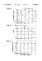
- FIG. 3 is a graph showing the power circulating in the loop for the non-linear optical mirror shown in FIG. 1, and the resultant non-linear phase difference produced by various input peak powers;
- FIG. 4 is a graph showing the peak output power from the embodiment of FIG. 1 as a function of peak input power for three pulse repetition rates;
- FIG. 5 is a graph of the non-linear phase of the embodiment of FIG. 1 as a function of input peak power
- FIG. 6 is a graph showing the gain of the embodiment of FIG. 1 as a function of input peak power compared to the gain provided by the amplifier of the embodiment of FIG. 1 alone;
- FIG. 7 is a graph showing the compression ratio provided by the embodiment of FIG. 2;
- FIGS. 8a and 8b are reproductions of an oscillogram showing the auto-correlation traces of input pulses with substantial inter-pulse radiation and pedestal free, compressed pulses amplified by the embodiment of FIG. 1, respectively;
- FIG. 9 is a graph showing the auto-correlation width compression ratio as a function of input power.
- FIG. 10 is a graph showing the gain verses average input power of the embodiment of FIG. 1.
- FIG. 1 shows an optical transmission system formed from a Sagnac loop interferometer 2 which comprises a four-port, fused-fibre optical coupler 4 having first and second input ports 6 and 8, and first and second output ports 10 and 12.
- the output ports 10 and 12 are optically coupled by an optical fibre loop 14.
- the interferometer 2 is conveniently formed from a single optical fibre 14, two portions of which are fused to form the coupler 4.
- the loop 14 comprises an 8.8 km length of dispersion-shifted fibre with a dispersion zero around 1.55 ⁇ m obtained from Corning Corporation. The nature of this fibre ensures that pulse shaping due to propagation effects is negligible.
- Fibre polarisation controllers 16 are also included in the loop 14 to adjust the device to reflection mode at low powers.
- a 30 m long erbium doped fibre amplifier (EDFA) 18 is spliced to the output port 10 of the fibre coupler 4.
- An optical fibre coupler 20 is used to couple pump radiation for the EDFA 18 from a high-power MQW semiconductor laser 22 with a maximum pump power of the order of 50 mW at 1.48 ⁇ m. Under these conditions, the EDFA 18 has a small signal gain of 28 dB, and a time-average saturation power of 24 ⁇ W.
- the saturation power of the amplifier is of the order of 0.6 mW.
- An optical source 24 (an actively mode-locked semiconductor laser providing pulses at 1.545 ⁇ m of about 12 ps duration at a repetition rate of 2.5 GHz and a mean power of about 50 ⁇ W) is connected to the input port 6.
- the measured time-bandwidth products of the pulses produced by the laser 24 are at best 0.4.
- P t and P i are the transmitted and input powers respectively
- ⁇ is the power coupling coefficient of the coupler
- L is the loop length
- ⁇ is the wavelength
- a eff is the effective fibre core area
- G is the power gain (P out /P in ) of the amplifier.
- FIG. 6 shows the computed gain characteristics for sech 2 intensity profile pulses (dashed curve).
- the fibre amplifier gain characteristics are also shown for the same values of G SS and P sat (full curve).
- the device At low input powers, the device is in reflecting mode, and hence the small signal gain is well suppressed. As the input power is increased, however, the device approaches a transmitting state, and the efficiency closely follows that of the EDFA 18 for P i >P Sa . It is expected that the varying response of the loop throughout the pulse gives rise to incomplete switching and pulse shaping. Although this is largely responsible for the small (2-3 dB) reduction in efficiency relative to the EDFA 18 at high powers, the loop amplifier benefits from pulse compression and low-level light suppression.
- Pulse durations are inferred from the second harmonic auto-correlation measurements.
- the auto-correlation shape of the transmitted pulses does not change significantly as a function of the input power, this being clearly illustrated in FIG. 9, where the ratio of the input and output correlation widths is plotted against the input power for average powers up to 3.5 mW (120 mW peak). It should be noted that the ratio of about 0.55 varies by less than 20% over a range of power of the order of 200 ⁇ P Sa .
- the device gain follows the trend described in FIG. 6, with a maximum of 17 dB occurring at an average input power of 50 ⁇ W (1.6 mW peak). The performance is well in keeping with that indicated by FIG. 6, bearing in mind a 3 dB loss associated with the loop fibre 14 and a lower (28 dB) EDFA gain. It should also be noted that the measured time-bandwidth products of the filtered pulses are essentially the same as the input.
- FIGS. 8a and 8b A further clear demonstration of the intensity filtering properties is shown in FIGS. 8a and 8b.
- the amplified, shortened (to 6 ps) and pedestal-free output (FIG. 8b) is shown for input pulses with substantial interpulse radiation (FIG. 8a). This behaviour is observed over the total range of input power.
- FIG. 2 A further embodiment of the present invention is shown in FIG. 2, in which the erbium amplifier 18 of FIG. 1 is now coupled to the input port 6 of the interferometer 2. Like elements are given the same reference numerals as in FIG. 1.
- the ratio of the switching powers of the devices of FIG. 1 and FIG. 2 is, therefore, given by
- ⁇ 0.4
- the switching power advantage of the device of FIG. 1 is at most a factor of 3.
- the switching power rapidly goes to infinity.
- FIG. 3 there is shown the power circulating in the two counter-propagating directions as a function of input peak power for the embodiment of FIG. 1, where (a) is the power circulating anti-clockwise between the port 12 and the input of the erbium amplifier 18, and (b) is the power circulating in the loop in a clockwise direction from the erbium amplifier to the output port 12.
- the solid curve (c) of the graph of FIG. 3 shows the non-linear phase shift of the pulses circulating in the two directions round the loop as a function of input peak power; and, as can be clearly seen, the non-linear phase shift becomes substantially constant at higher peak powers.
- FIG. 4 there is shown a graph of the peak output power from the port 8 as a function of peak input power (in mW) of an optical signal input at the input port 6 at three different pulse repetition rates f equal to 1, 2 and 3 kHz.
- P sat equals five times the switching power, P Sa , of the interferometer of FIG. 1.
- the output power is an oscillatory function of the input power. As the saturation power moves closer to the switching power with increasing frequency, the peak output power becomes more nearly a constant for peak input powers corresponding to P Sa .
- FIG. 10 there is shown a graph of the gain of the embodiment of FIG. 1 as a function of the average input power of the optical signals from the optical source 24.
Landscapes
- Physics & Mathematics (AREA)
- Nonlinear Science (AREA)
- Engineering & Computer Science (AREA)
- Computer Networks & Wireless Communication (AREA)
- Signal Processing (AREA)
- Electromagnetism (AREA)
- Power Engineering (AREA)
- General Physics & Mathematics (AREA)
- Optics & Photonics (AREA)
- Optical Communication System (AREA)
- Instruments For Measurement Of Length By Optical Means (AREA)
- Spectrometry And Color Measurement (AREA)
- Lasers (AREA)
Applications Claiming Priority (3)
| Application Number | Priority Date | Filing Date | Title |
|---|---|---|---|
| GB9118843 | 1991-09-03 | ||
| GB919118843A GB9118843D0 (en) | 1991-09-03 | 1991-09-03 | An optical transmission system |
| PCT/GB1992/001579 WO1993005592A1 (en) | 1991-09-03 | 1992-08-28 | Non-linear optical interferometer with saturated amplifier |
Publications (1)
| Publication Number | Publication Date |
|---|---|
| US5479291A true US5479291A (en) | 1995-12-26 |
Family
ID=10700847
Family Applications (1)
| Application Number | Title | Priority Date | Filing Date |
|---|---|---|---|
| US08/199,299 Expired - Lifetime US5479291A (en) | 1991-09-03 | 1992-08-28 | Non-linear optical interferometer with saturated amplifier |
Country Status (12)
| Country | Link |
|---|---|
| US (1) | US5479291A (de) |
| EP (1) | EP0602089B1 (de) |
| JP (1) | JPH06510135A (de) |
| KR (1) | KR100272402B1 (de) |
| AT (1) | ATE200368T1 (de) |
| AU (1) | AU656225B2 (de) |
| CA (1) | CA2112596C (de) |
| DE (1) | DE69231767T2 (de) |
| ES (1) | ES2157206T3 (de) |
| GB (2) | GB9118843D0 (de) |
| HK (1) | HK154696A (de) |
| WO (1) | WO1993005592A1 (de) |
Cited By (23)
| Publication number | Priority date | Publication date | Assignee | Title |
|---|---|---|---|---|
| US5533154A (en) * | 1991-10-18 | 1996-07-02 | British Telecommunications, Plc | Optical memory |
| US5596449A (en) * | 1995-02-24 | 1997-01-21 | Ando Electric Co., Ltd. | Light pulse generator |
| US5825530A (en) * | 1994-12-02 | 1998-10-20 | Hewlett-Packard Company | Arrangement and method for operating and testing an optical device |
| US5999287A (en) * | 1994-12-23 | 1999-12-07 | British Telecommunications Public Limited Company | Node in optical TDM network |
| US6157762A (en) * | 1996-12-09 | 2000-12-05 | The Regents Of The University Of California | Nonlinear pulse reshaping for optical fiber transmission systems |
| US6295308B1 (en) * | 1999-08-31 | 2001-09-25 | Corning Incorporated | Wavelength-locked external cavity lasers with an integrated modulator |
| US6335820B1 (en) | 1999-12-23 | 2002-01-01 | Xtera Communications, Inc. | Multi-stage optical amplifier and broadband communication system |
| US6356384B1 (en) | 1998-03-24 | 2002-03-12 | Xtera Communications Inc. | Broadband amplifier and communication system |
| US6359725B1 (en) | 1998-06-16 | 2002-03-19 | Xtera Communications, Inc. | Multi-stage optical amplifier and broadband communication system |
| US6370164B1 (en) | 1996-12-23 | 2002-04-09 | Xtera Communications, Inc. | Broadband sagnac raman amplifiers and cascade lasers |
| US6374006B1 (en) | 1998-03-20 | 2002-04-16 | Xtera Communications, Inc. | Chirped period gratings for raman amplification in circulator loop cavities |
| US6404541B2 (en) * | 2000-03-24 | 2002-06-11 | Oprel Technologies Inc. | Optical amplifier with active-fiber loop mirror |
| US6421482B1 (en) * | 1998-12-23 | 2002-07-16 | Telefonaktiebolaget Lm Ericsson (Publ) | Device for reflecting light |
| US6567430B1 (en) | 1998-09-21 | 2003-05-20 | Xtera Communications, Inc. | Raman oscillator including an intracavity filter and amplifiers utilizing same |
| US6574037B2 (en) | 1998-06-16 | 2003-06-03 | Xtera Communications, Inc. | All band amplifier |
| US6600592B2 (en) | 1998-03-24 | 2003-07-29 | Xtera Communications, Inc. | S+ band nonlinear polarization amplifiers |
| US6631025B2 (en) | 2000-01-12 | 2003-10-07 | Xtera Communications, Inc. | Low-noise distributed Raman amplifier using bi-directional pumping using multiple Raman orders |
| US6744553B1 (en) | 2000-06-20 | 2004-06-01 | Xtera Communications, Inc. | System and method for converting a plurality of wavelengths |
| US6760509B2 (en) | 2000-02-14 | 2004-07-06 | The Regents Of The University Of Michigan | SNR booster for WDM systems |
| US6760148B2 (en) | 1998-03-24 | 2004-07-06 | Xtera Communications, Inc. | Nonlinear polarization amplifiers in nonzero dispersion shifted fiber |
| US6885498B2 (en) | 1998-06-16 | 2005-04-26 | Xtera Communications, Inc. | Multi-stage optical amplifier and broadband communication system |
| US6985283B1 (en) | 1998-06-16 | 2006-01-10 | Xtera Communications, Inc. | Fiber-optic compensation for dispersion, gain tilt, and band pump nonlinearity |
| US20070110450A1 (en) * | 2003-09-17 | 2007-05-17 | Antonella Bogoni | Optical signal regenerator for high bit-rate transmission systems |
Families Citing this family (5)
| Publication number | Priority date | Publication date | Assignee | Title |
|---|---|---|---|---|
| EP0567693A1 (de) * | 1992-04-27 | 1993-11-03 | BRITISH TELECOMMUNICATIONS public limited company | Optische Taktrückgewinnung |
| JP4440343B2 (ja) * | 1995-03-24 | 2010-03-24 | ブリティッシュ・テレコミュニケーションズ・パブリック・リミテッド・カンパニー | 光網 |
| EP0753787A1 (de) * | 1995-07-05 | 1997-01-15 | Koninklijke Philips Electronics N.V. | Optische Einheit zur Verarbeitung eines optischen Pulsmusters |
| CN1155173C (zh) * | 1998-02-16 | 2004-06-23 | 皇家菲利浦电子有限公司 | 配有采用全光学时钟恢复接收机的光传输系统 |
| JP2005173530A (ja) * | 2003-11-17 | 2005-06-30 | Osaka Industrial Promotion Organization | 光信号処理方法及び装置、非線形光ループミラーとその設計方法並びに光信号変換方法 |
Citations (2)
| Publication number | Priority date | Publication date | Assignee | Title |
|---|---|---|---|---|
| US5309267A (en) * | 1992-09-25 | 1994-05-03 | At&T Bell Laboratories | Optical communication system using a Sagnac switch |
| US5369520A (en) * | 1992-05-22 | 1994-11-29 | At&T Corp. | Optical regeneration circuit |
-
1991
- 1991-09-03 GB GB919118843A patent/GB9118843D0/en active Pending
-
1992
- 1992-08-28 CA CA002112596A patent/CA2112596C/en not_active Expired - Fee Related
- 1992-08-28 EP EP92918236A patent/EP0602089B1/de not_active Expired - Lifetime
- 1992-08-28 AT AT92918236T patent/ATE200368T1/de not_active IP Right Cessation
- 1992-08-28 JP JP5505027A patent/JPH06510135A/ja active Pending
- 1992-08-28 DE DE69231767T patent/DE69231767T2/de not_active Expired - Lifetime
- 1992-08-28 GB GB9325690A patent/GB2274036B/en not_active Expired - Fee Related
- 1992-08-28 ES ES92918236T patent/ES2157206T3/es not_active Expired - Lifetime
- 1992-08-28 US US08/199,299 patent/US5479291A/en not_active Expired - Lifetime
- 1992-08-28 WO PCT/GB1992/001579 patent/WO1993005592A1/en not_active Ceased
- 1992-08-28 AU AU24923/92A patent/AU656225B2/en not_active Ceased
- 1992-08-28 KR KR1019940700509A patent/KR100272402B1/ko not_active Expired - Fee Related
-
1996
- 1996-08-15 HK HK154696A patent/HK154696A/xx not_active IP Right Cessation
Patent Citations (2)
| Publication number | Priority date | Publication date | Assignee | Title |
|---|---|---|---|---|
| US5369520A (en) * | 1992-05-22 | 1994-11-29 | At&T Corp. | Optical regeneration circuit |
| US5309267A (en) * | 1992-09-25 | 1994-05-03 | At&T Bell Laboratories | Optical communication system using a Sagnac switch |
Non-Patent Citations (20)
| Title |
|---|
| Betts et al., "All-Optical Pulse Compression Using Amplifying Sagnac Loop", Electronics Letters, vol. 27, No. 10, 9 May 1991, Stevenage GB, pp. 858-860. |
| Betts et al., All Optical Pulse Compression Using Amplifying Sagnac Loop , Electronics Letters, vol. 27, No. 10, 9 May 1991, Stevenage GB, pp. 858 860. * |
| Fermann et al., "Nonlinear Amplifying Loop Mirror", Optics Letters, vol. 15, No. 13, 1 Jul. 1990, New York, US, pp. 752-754. |
| Fermann et al., "Nonlinear Amplifying Loop Mirror", Optics Letters, vol. 15, No. 13, Jul. 1, 1990, pp. 752-754. |
| Fermann et al., Nonlinear Amplifying Loop Mirror , Optics Letters, vol. 15, No. 13, 1 Jul. 1990, New York, US, pp. 752 754. * |
| Fermann et al., Nonlinear Amplifying Loop Mirror , Optics Letters, vol. 15, No. 13, Jul. 1, 1990, pp. 752 754. * |
| Jinno et al., "Demonstration of Laser-Diode-Pumped Ultrafast All-Optical Switching in a Nonlinear Sagnac Interferometer", Electronics Letters, vol. 27, No. 1, 3 Jan. 1991, Stevenage GB, pp. 75-76. |
| Jinno et al., "Demonstration of Laser-Diode-Pumped Ultrafast All-optical Switching in a Nonlinear Sagnac Interferometer", Electronics Letters, vol. 27, No. 1, 3 Jan. 1991, Stevenage, GB, pp. 75-76. |
| Jinno et al., Demonstration of Laser Diode Pumped Ultrafast All Optical Switching in a Nonlinear Sagnac Interferometer , Electronics Letters, vol. 27, No. 1, 3 Jan. 1991, Stevenage GB, pp. 75 76. * |
| Jinno et al., Demonstration of Laser Diode Pumped Ultrafast All optical Switching in a Nonlinear Sagnac Interferometer , Electronics Letters, vol. 27, No. 1, 3 Jan. 1991, Stevenage, GB, pp. 75 76. * |
| Richardson et al., "Very Low Threshold Sagnac Switch Incorporating an Erbium Doped Fibre Amplifier", Electronics Letters, vol. 26, No. 21, 11 Oct. 1990, Stevenage GB, pp. 1779-1781. |
| Richardson et al., Very Low Threshold Sagnac Switch Incorporating an Erbium Doped Fibre Amplifier , Electronics Letters, vol. 26, No. 21, 11 Oct. 1990, Stevenage GB, pp. 1779 1781. * |
| Smith et al., "Pulse Amplification and Shaping Using a Nonlinear Loop Mirror that Incorporates a Saturable Gain", a reprint from Optics Letters, pp. 408-410. |
| smith et al., "Square Pulse Amplification Using Nonlinear Loop Mirror Incorporating Saturable Gain", Electronics Letters, 24th Oct. 1991, vol. 27, pp. 2046-2047. |
| Smith et al., Pulse Amplification and Shaping Using a Nonlinear Loop Mirror that Incorporates a Saturable Gain , a reprint from Optics Letters, pp. 408 410. * |
| smith et al., Square Pulse Amplification Using Nonlinear Loop Mirror Incorporating Saturable Gain , Electronics Letters, 24th Oct. 1991, vol. 27, pp. 2046 2047. * |
| Yamada et al., "Automatic Intensity Control of an Optical Transmission Line Using Enhanced Gain Saturation in Cascaded Optical Amplifiers", IEEE Journal of Quantum Electronics, 27 Jan. 1991, No. 1, New York, US, pp. 146-151. |
| Yamada et al., "Automatic Intensity Control of an Optical Transmission Line Using Enhanced Gain Saturation in Cascaded Optical Amplifiers", IEEE Journal of Quantum Electronics, vol. 27, No. 1, Jan. 1991, New York, US, pp. 146-151. |
| Yamada et al., Automatic Intensity Control of an Optical Transmission Line Using Enhanced Gain Saturation in Cascaded Optical Amplifiers , IEEE Journal of Quantum Electronics, 27 Jan. 1991, No. 1, New York, US, pp. 146 151. * |
| Yamada et al., Automatic Intensity Control of an Optical Transmission Line Using Enhanced Gain Saturation in Cascaded Optical Amplifiers , IEEE Journal of Quantum Electronics, vol. 27, No. 1, Jan. 1991, New York, US, pp. 146 151. * |
Cited By (28)
| Publication number | Priority date | Publication date | Assignee | Title |
|---|---|---|---|---|
| US5533154A (en) * | 1991-10-18 | 1996-07-02 | British Telecommunications, Plc | Optical memory |
| US5825530A (en) * | 1994-12-02 | 1998-10-20 | Hewlett-Packard Company | Arrangement and method for operating and testing an optical device |
| US5999287A (en) * | 1994-12-23 | 1999-12-07 | British Telecommunications Public Limited Company | Node in optical TDM network |
| US5596449A (en) * | 1995-02-24 | 1997-01-21 | Ando Electric Co., Ltd. | Light pulse generator |
| US6157762A (en) * | 1996-12-09 | 2000-12-05 | The Regents Of The University Of California | Nonlinear pulse reshaping for optical fiber transmission systems |
| US6370164B1 (en) | 1996-12-23 | 2002-04-09 | Xtera Communications, Inc. | Broadband sagnac raman amplifiers and cascade lasers |
| US6833946B2 (en) | 1996-12-23 | 2004-12-21 | Xtera Communications, Inc. | Optical amplification using polarization diversity pumping |
| US6374006B1 (en) | 1998-03-20 | 2002-04-16 | Xtera Communications, Inc. | Chirped period gratings for raman amplification in circulator loop cavities |
| US6760148B2 (en) | 1998-03-24 | 2004-07-06 | Xtera Communications, Inc. | Nonlinear polarization amplifiers in nonzero dispersion shifted fiber |
| US6356384B1 (en) | 1998-03-24 | 2002-03-12 | Xtera Communications Inc. | Broadband amplifier and communication system |
| US6693738B2 (en) * | 1998-03-24 | 2004-02-17 | The Regents Of The University Of Michigan | Broadband amplifier and communication system |
| US6600592B2 (en) | 1998-03-24 | 2003-07-29 | Xtera Communications, Inc. | S+ band nonlinear polarization amplifiers |
| US6580548B2 (en) | 1998-03-24 | 2003-06-17 | Xtera Communications, Inc. | Broadband amplifier and communication system |
| US6574037B2 (en) | 1998-06-16 | 2003-06-03 | Xtera Communications, Inc. | All band amplifier |
| US6985283B1 (en) | 1998-06-16 | 2006-01-10 | Xtera Communications, Inc. | Fiber-optic compensation for dispersion, gain tilt, and band pump nonlinearity |
| US6359725B1 (en) | 1998-06-16 | 2002-03-19 | Xtera Communications, Inc. | Multi-stage optical amplifier and broadband communication system |
| US6885498B2 (en) | 1998-06-16 | 2005-04-26 | Xtera Communications, Inc. | Multi-stage optical amplifier and broadband communication system |
| US6567430B1 (en) | 1998-09-21 | 2003-05-20 | Xtera Communications, Inc. | Raman oscillator including an intracavity filter and amplifiers utilizing same |
| US6421482B1 (en) * | 1998-12-23 | 2002-07-16 | Telefonaktiebolaget Lm Ericsson (Publ) | Device for reflecting light |
| US6295308B1 (en) * | 1999-08-31 | 2001-09-25 | Corning Incorporated | Wavelength-locked external cavity lasers with an integrated modulator |
| US6335820B1 (en) | 1999-12-23 | 2002-01-01 | Xtera Communications, Inc. | Multi-stage optical amplifier and broadband communication system |
| US6631025B2 (en) | 2000-01-12 | 2003-10-07 | Xtera Communications, Inc. | Low-noise distributed Raman amplifier using bi-directional pumping using multiple Raman orders |
| US6714342B2 (en) | 2000-01-12 | 2004-03-30 | Xtera Communications, Inc. | Low-noise distributed Raman amplifier using bi-directional pumping using multiple Raman orders |
| US6760509B2 (en) | 2000-02-14 | 2004-07-06 | The Regents Of The University Of Michigan | SNR booster for WDM systems |
| US6404541B2 (en) * | 2000-03-24 | 2002-06-11 | Oprel Technologies Inc. | Optical amplifier with active-fiber loop mirror |
| US6919986B2 (en) | 2000-05-05 | 2005-07-19 | Xtera Communications, Inc. | Nonlinear polarization amplifiers in nonzero dispersion shifted fiber |
| US6744553B1 (en) | 2000-06-20 | 2004-06-01 | Xtera Communications, Inc. | System and method for converting a plurality of wavelengths |
| US20070110450A1 (en) * | 2003-09-17 | 2007-05-17 | Antonella Bogoni | Optical signal regenerator for high bit-rate transmission systems |
Also Published As
| Publication number | Publication date |
|---|---|
| GB9118843D0 (en) | 1991-10-16 |
| GB9325690D0 (en) | 1994-03-09 |
| AU2492392A (en) | 1993-04-05 |
| CA2112596C (en) | 1998-01-20 |
| CA2112596A1 (en) | 1993-03-18 |
| EP0602089B1 (de) | 2001-04-04 |
| DE69231767T2 (de) | 2001-10-25 |
| ATE200368T1 (de) | 2001-04-15 |
| HK154696A (en) | 1996-08-23 |
| AU656225B2 (en) | 1995-01-27 |
| EP0602089A1 (de) | 1994-06-22 |
| GB2274036A (en) | 1994-07-06 |
| KR100272402B1 (ko) | 2000-11-15 |
| GB2274036B (en) | 1995-07-05 |
| ES2157206T3 (es) | 2001-08-16 |
| DE69231767D1 (de) | 2001-05-10 |
| JPH06510135A (ja) | 1994-11-10 |
| WO1993005592A1 (en) | 1993-03-18 |
Similar Documents
| Publication | Publication Date | Title |
|---|---|---|
| EP0602089B1 (de) | Nicht-lineares optisches Interferometer mit gesättigtem Verstärker | |
| US5574739A (en) | Polarization-stable pulsed laser | |
| US5050183A (en) | Figure eight shaped coherent optical pulse source | |
| US5778014A (en) | Sagnac raman amplifiers and cascade lasers | |
| Agrawal | Nonlinear fiber optics | |
| US5898716A (en) | Structure of a passively mode-locked optical fiber laser | |
| US5757529A (en) | In-line regenerating apparatus for regenerating a soliton-conveyed signal by synchronously modulating the solitons by means of a non-linear optical loop mirror | |
| US6453082B1 (en) | Device and system for waveform shaping | |
| US6259552B1 (en) | Optical wavelength converter | |
| EP1430574A2 (de) | Faseroptische vorrichtungen unter verwendung des raman-effekts | |
| US5058986A (en) | Non-linear inferferometer | |
| Deshmukh et al. | Four wave mixing in DWDM optical system | |
| Ngo et al. | Graphical representation and analysis of the Z-shaped double-coupler optical resonator | |
| AU742088B2 (en) | Optical wavelength converter | |
| WO1993003406A1 (en) | Sagnac loop gates | |
| Dahir et al. | Dispersion Compensation by Using FBG and Low Pass Gaussian Filter. | |
| Kagi et al. | Fiber optical parametric amplifier operating near zero-dispersion wavelength | |
| Duling | All-fiber modelocked figure eight laser | |
| Chi et al. | 2R regenerator based on high non-linear dispersion-imbalanced loop mirror | |
| KR20050027638A (ko) | 광 펄스의 소광비 향상장치 | |
| Erro et al. | Third-order dispersion in linearly chirped Bragg gratings and its compensation | |
| Doughty et al. | Novel acoustically tuned fibre laser | |
| Evans | Dispersion-tapered fiber in nonlinear loop mirrors for intensity and pulse width switching | |
| Escalera-Santos et al. | Stimulated Raman Scattering for All Optical Switches | |
| Man et al. | Optimal loop length of a nonlinear optical loop mirror in switching solitons |
Legal Events
| Date | Code | Title | Description |
|---|---|---|---|
| AS | Assignment |
Owner name: BRITISH TELECOMMUNICATIONS PUBLIC LIMITED COMPANY, Free format text: ASSIGNMENT OF ASSIGNORS INTEREST;ASSIGNORS:SMITH, KEVIN;GREER, ELAINE JANE;REEL/FRAME:007086/0307;SIGNING DATES FROM 19940314 TO 19940331 |
|
| STCF | Information on status: patent grant |
Free format text: PATENTED CASE |
|
| FPAY | Fee payment |
Year of fee payment: 4 |
|
| FPAY | Fee payment |
Year of fee payment: 8 |
|
| FEPP | Fee payment procedure |
Free format text: PAYOR NUMBER ASSIGNED (ORIGINAL EVENT CODE: ASPN); ENTITY STATUS OF PATENT OWNER: LARGE ENTITY |
|
| FPAY | Fee payment |
Year of fee payment: 12 |
|
| AS | Assignment |
Owner name: IPG PHOTONICS CORPORATION, MASSACHUSETTS Free format text: ASSIGNMENT OF ASSIGNORS INTEREST;ASSIGNOR:BRITISH TELECOMMUNICATIONS PLC;REEL/FRAME:020582/0143 Effective date: 20080221 |