US547761A - Island - Google Patents
Island Download PDFInfo
- Publication number
- US547761A US547761A US547761DA US547761A US 547761 A US547761 A US 547761A US 547761D A US547761D A US 547761DA US 547761 A US547761 A US 547761A
- Authority
- US
- United States
- Prior art keywords
- switch
- car
- roller
- tongues
- track
- Prior art date
- Legal status (The legal status is an assumption and is not a legal conclusion. Google has not performed a legal analysis and makes no representation as to the accuracy of the status listed.)
- Expired - Lifetime
Links
- 210000002105 tongue Anatomy 0.000 description 8
- 241000220010 Rhode Species 0.000 description 1
- 238000013459 approach Methods 0.000 description 1
Images
Classifications
-
- B—PERFORMING OPERATIONS; TRANSPORTING
- B61—RAILWAYS
- B61L—GUIDING RAILWAY TRAFFIC; ENSURING THE SAFETY OF RAILWAY TRAFFIC
- B61L11/00—Operation of points from the vehicle or by the passage of the vehicle
- B61L11/02—Operation of points from the vehicle or by the passage of the vehicle using mechanical interaction between vehicle and track
Definitions
- This invention relates to that class of streetcalled automatic -that is, adapted to be operated by devices attached to the car, though those devices are under the controlof the person running the car as to the way in which the switch shall be moved. It is fully explained and illustrated in this specification and the accompanying drawings.
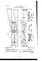
- Figure 1 is a top view of a portion of a railway-track, sufficient to show all that pertains to the invention.
- Fig. 2 shows a vertical section taken lengthwise of the track on line y y in Fig. 1, looking at the farther side of the section.
- Fig. 3 shows a vertical cross section of the railway-track, taken on linear; as, Fig. 1, representing the devices for raising and lowering the switch-tongues.
- Fig.4 is another vertical cross-section of the track, taken on lines 2 2, showing those devices that are moved by contact with the car in operating the switch.
- Figs. 5 and 6 are end views of the switch-operatin g roller.
- One feature of this invention is that the switch-tongues are raised and lowered in operating, instead of being moved sidewise, as they are in most cases.
- the switch-tongues B B are made in the ordinary shape, only instead of being pivoted at their fixed ends 0 0, so as to swing laterally, they are held in horizontal pivots or hinges, so that their free ends will move vertically from a position in which their topsare level with the permanent rails A A down, so as to be out of the way of the flange of a car-wheel.
- a stout roller or shaft 0 is placed across the rails A, a little below them, in substantial bearings e e, supported on the sleepers. Strong pins 3 s project out of'each end of the roller 0, outside of its center, into slots in the tongues,
- This roller 0 has an arm don its under side, connected by the bars 1% n to the devices operated by the car to change the switch. These devices consist on the left side in the drawings of a rocker-shaft j, held in bearings 0 0 between the rails A, provided with a downwardly-projecting arm 25, connected by a rod 'n to the arm (1 on the roller 0.
- the shaft j On the upper side of the shaft j are two wings o o, placed nearly quartering to each each other, so that when one wing is up the other will be down level with the track.
- a like shaft j is placed on the right of the switch, with similar wings 'u '0' and arm 15, which is connected by a rod n to the arm 01 on the roller 0.
- the wings o are arranged to be struck by a changeable device on the car under the control of the driver. This device on the car may be made to shift sidewise or vertically, as may be desired, to direct which wing 0 shall be pressed down and which track the car shall take.
- the changing device on the car is arranged to strike the wing 22 and turn the shaft j and by means of the rod n and arm at turn the roller 0 and cause the pin 8 to raise the switch-tongue B, the pin 3 turning slightly past the center, and at the same time cause the pin 3' to pull down the switch-tongue B out of the way and the car will continue on the straight track.
- the switch-operating device is set to strike the wing 0', which has been raised by the depression of the wing 'v, and turn the shafts j and 0 back, so as to raise the switchtongue B and lower the tongue B, by their respective pins and cause the car to turn 0% of the direct track onto the side track.
- the position of the wings can be easily seen by the driver of the car as it approaches the switch and the proper direction given to the changing device on the car.
- a roller having a pin in each end set on different sides of the center of the roller, switch tongues hinged at one end so that the free ends can be raised and lowered, and having their free ends held on said pins, a cross shaft having wings set at an angle to each other on its upper side and connected bya rod extending from a. downwardly extending arm on said shaft to a like arm on said roller, substantially as described.
Landscapes
- Engineering & Computer Science (AREA)
- Mechanical Engineering (AREA)
- Train Traffic Observation, Control, And Security (AREA)
Description
1. W. BLISS. STREET RAILWAY SWITCH.
Patented Oct. 15,1895.
. railway switches UNITED STATES i PATENT OFFICE.
IRVING W. BLISS, OF WARREN, RHODE ISLAND.
STREET-RAILWAY SWITCH.
SPECIFICATION forming Application filedOctoher 5, 1894.
To aZZ whom it may concern.-
Be it known that I, IRVING W. BLISS, of Warren, in the county of Bristol and State of Rhode Island, have invented certain new and useful Improvements in Street-Railway Switches; and Ido hereby declare that the following is a full, clear, and exact description thereof, reference being had to the accompanying drawings, and to the letters of reference marked thereon, which form a part of this specification.
This invention relates to that class of streetcalled automatic -that is, adapted to be operated by devices attached to the car, though those devices are under the controlof the person running the car as to the way in which the switch shall be moved. It is fully explained and illustrated in this specification and the accompanying drawings.
Figure 1 is a top view of a portion of a railway-track, sufficient to show all that pertains to the invention. Fig. 2 shows a vertical section taken lengthwise of the track on line y y in Fig. 1, looking at the farther side of the section. Fig. 3 shows a vertical cross section of the railway-track, taken on linear; as, Fig. 1, representing the devices for raising and lowering the switch-tongues. Fig.4 is another vertical cross-section of the track, taken on lines 2 2, showing those devices that are moved by contact with the car in operating the switch. Figs. 5 and 6 are end views of the switch-operatin g roller.
One feature of this invention is that the switch-tongues are raised and lowered in operating, instead of being moved sidewise, as they are in most cases.
The switch-tongues B B are made in the ordinary shape, only instead of being pivoted at their fixed ends 0 0, so as to swing laterally, they are held in horizontal pivots or hinges, so that their free ends will move vertically from a position in which their topsare level with the permanent rails A A down, so as to be out of the way of the flange of a car-wheel. To give the required vertical motion to the switch-tongues B B, a stout roller or shaft 0 is placed across the rails A, a little below them, in substantial bearings e e, supported on the sleepers. Strong pins 3 s project out of'each end of the roller 0, outside of its center, into slots in the tongues,
part of Letters Patent No. 547,761, dated October 15,1895.
Serial No. 524,995- (No model.)
the pin in one end being placed about quarter ing to the pin in the other end, so that when the roller is turned so that one pin is up the other pin will be about one-quarter the way down. These pins 8 3' support the free ends of the switch-tongues B B, and it will be readily seen that when one switch-tongue is up the other one will be down. This roller 0 has an arm don its under side, connected by the bars 1% n to the devices operated by the car to change the switch. These devices consist on the left side in the drawings of a rocker-shaft j, held in bearings 0 0 between the rails A, provided with a downwardly-projecting arm 25, connected by a rod 'n to the arm (1 on the roller 0.
On the upper side of the shaft j are two wings o o, placed nearly quartering to each each other, so that when one wing is up the other will be down level with the track. A like shaft j is placed on the right of the switch, with similar wings 'u '0' and arm 15, which is connected by a rod n to the arm 01 on the roller 0. The wings o are arranged to be struck by a changeable device on the car under the control of the driver. This device on the car may be made to shift sidewise or vertically, as may be desired, to direct which wing 0 shall be pressed down and which track the car shall take. If the car is proceeding from left to right and it is desired to keep the straight track, the changing device on the car is arranged to strike the wing 22 and turn the shaft j and by means of the rod n and arm at turn the roller 0 and cause the pin 8 to raise the switch-tongue B, the pin 3 turning slightly past the center, and at the same time cause the pin 3' to pull down the switch-tongue B out of the way and the car will continue on the straight track. If the next car going in the same direction is intended to turn off on the side track, its switch-operating device is set to strike the wing 0', which has been raised by the depression of the wing 'v, and turn the shafts j and 0 back, so as to raise the switchtongue B and lower the tongue B, by their respective pins and cause the car to turn 0% of the direct track onto the side track. The position of the wings can be easily seen by the driver of the car as it approaches the switch and the proper direction given to the changing device on the car. This makes a very simple switch-operating device that holds the switchtongues up securely against any load passing over them, because the pins .3, when they raise one of the tongues, pass a little by the center of the roller, and no amount of pressure on the tongue will turn it back to let itdown.
Having thus described my improvements, I claim as my invention and desire to secure by Letters Patent- 1. In a railway switch the combination of a roller having a pin in each end set on different sides of the center of the roller, single switch tongues hinged at one end so that their free ends can be raised and lowered, and having their free ends held on said pins in slots in said tongues of proper length to lock said pins when the tongues are raised, with means for operating said roller by an attachment on a car, substantially as described.
2. In a railway switch, the combination of a roller having a pin in each end set on different sides of the center of the roller, switch tongues hinged at one end so that the free ends can be raised and lowered, and having their free ends held on said pins, a cross shaft having wings set at an angle to each other on its upper side and connected bya rod extending from a. downwardly extending arm on said shaft to a like arm on said roller, substantially as described.
IRVING W. BLISS. Witnesses:
E. B. READ, BENJ. ARNOLD.
Publications (1)
| Publication Number | Publication Date |
|---|---|
| US547761A true US547761A (en) | 1895-10-15 |
Family
ID=2616504
Family Applications (1)
| Application Number | Title | Priority Date | Filing Date |
|---|---|---|---|
| US547761D Expired - Lifetime US547761A (en) | Island |
Country Status (1)
| Country | Link |
|---|---|
| US (1) | US547761A (en) |
-
0
- US US547761D patent/US547761A/en not_active Expired - Lifetime
Similar Documents
| Publication | Publication Date | Title |
|---|---|---|
| US547761A (en) | Island | |
| US820406A (en) | Railroad-frog. | |
| US736911A (en) | Railway-switch. | |
| US832840A (en) | Railway-switch. | |
| US339411A (en) | Automatic railroad-switch | |
| US823764A (en) | Railway-switch. | |
| US310396A (en) | Railway-switch | |
| US1222577A (en) | Railway-switch. | |
| US194864A (en) | Improvement in railway-gates | |
| US463074A (en) | Foot-guard for switches | |
| US437976A (en) | Railroad-crossing | |
| US219475A (en) | Improvement in railroad-switches | |
| US600720A (en) | Railroad switch and frog | |
| US323585A (en) | Railway-frog | |
| US177603A (en) | Improvement in street-railway turn-outs | |
| US1176968A (en) | Railway-switch. | |
| US375048A (en) | Railway-switch | |
| US394118A (en) | Frogless switch | |
| US584486A (en) | Railroad-frog | |
| US294664A (en) | Railroad-frog | |
| US863416A (en) | Railway-switch. | |
| US319398A (en) | Heebeet l | |
| US453405A (en) | Railway-switch | |
| US1105078A (en) | Gate for railway-crossings. | |
| US139589A (en) | Improvement in railroad switches |