US5473162A - Infrared emission detection of a gas - Google Patents
Infrared emission detection of a gas Download PDFInfo
- Publication number
- US5473162A US5473162A US08/123,733 US12373393A US5473162A US 5473162 A US5473162 A US 5473162A US 12373393 A US12373393 A US 12373393A US 5473162 A US5473162 A US 5473162A
- Authority
- US
- United States
- Prior art keywords
- infrared
- sample
- selected component
- flame
- emission
- Prior art date
- Legal status (The legal status is an assumption and is not a legal conclusion. Google has not performed a legal analysis and makes no representation as to the accuracy of the status listed.)
- Expired - Fee Related
Links
- 238000001514 detection method Methods 0.000 title claims description 90
- 230000005284 excitation Effects 0.000 claims abstract description 133
- 239000000460 chlorine Substances 0.000 claims abstract description 119
- 238000000034 method Methods 0.000 claims abstract description 116
- 230000005855 radiation Effects 0.000 claims abstract description 113
- 229910052801 chlorine Inorganic materials 0.000 claims abstract description 99
- VEXZGXHMUGYJMC-UHFFFAOYSA-M Chloride anion Chemical compound [Cl-] VEXZGXHMUGYJMC-UHFFFAOYSA-M 0.000 claims abstract description 87
- OKTJSMMVPCPJKN-UHFFFAOYSA-N Carbon Chemical compound [C] OKTJSMMVPCPJKN-UHFFFAOYSA-N 0.000 claims abstract description 56
- 229910052799 carbon Inorganic materials 0.000 claims abstract description 55
- ZAMOUSCENKQFHK-UHFFFAOYSA-N Chlorine atom Chemical compound [Cl] ZAMOUSCENKQFHK-UHFFFAOYSA-N 0.000 claims abstract 5
- KZBUYRJDOAKODT-UHFFFAOYSA-N Chlorine Chemical compound ClCl KZBUYRJDOAKODT-UHFFFAOYSA-N 0.000 claims description 150
- 150000001875 compounds Chemical class 0.000 claims description 62
- 239000000126 substance Substances 0.000 claims description 51
- 238000005259 measurement Methods 0.000 claims description 43
- 238000004458 analytical method Methods 0.000 claims description 38
- YCKRFDGAMUMZLT-UHFFFAOYSA-N Fluorine atom Chemical compound [F] YCKRFDGAMUMZLT-UHFFFAOYSA-N 0.000 claims description 27
- 229910052731 fluorine Inorganic materials 0.000 claims description 27
- 239000011737 fluorine Substances 0.000 claims description 27
- 230000001590 oxidative effect Effects 0.000 claims description 21
- -1 hypochlorite ions Chemical class 0.000 claims description 15
- 239000007788 liquid Substances 0.000 claims description 14
- 150000002894 organic compounds Chemical class 0.000 claims description 14
- WQYVRQLZKVEZGA-UHFFFAOYSA-N hypochlorite Inorganic materials Cl[O-] WQYVRQLZKVEZGA-UHFFFAOYSA-N 0.000 claims description 11
- QWPPOHNGKGFGJK-UHFFFAOYSA-N hypochlorous acid Chemical compound ClO QWPPOHNGKGFGJK-UHFFFAOYSA-N 0.000 claims description 11
- 238000012545 processing Methods 0.000 claims description 8
- 150000004649 carbonic acid derivatives Chemical class 0.000 claims description 7
- 238000002329 infrared spectrum Methods 0.000 claims description 7
- 230000002401 inhibitory effect Effects 0.000 claims description 6
- 230000008016 vaporization Effects 0.000 claims description 6
- 238000010183 spectrum analysis Methods 0.000 claims description 4
- 230000009977 dual effect Effects 0.000 abstract description 24
- 239000007789 gas Substances 0.000 description 158
- 239000000523 sample Substances 0.000 description 139
- CURLTUGMZLYLDI-UHFFFAOYSA-N Carbon dioxide Chemical compound O=C=O CURLTUGMZLYLDI-UHFFFAOYSA-N 0.000 description 133
- 239000003570 air Substances 0.000 description 94
- UFHFLCQGNIYNRP-UHFFFAOYSA-N Hydrogen Chemical compound [H][H] UFHFLCQGNIYNRP-UHFFFAOYSA-N 0.000 description 87
- 239000001257 hydrogen Substances 0.000 description 87
- 229910052739 hydrogen Inorganic materials 0.000 description 87
- IJGRMHOSHXDMSA-UHFFFAOYSA-N Atomic nitrogen Chemical compound N#N IJGRMHOSHXDMSA-UHFFFAOYSA-N 0.000 description 84
- VLKZOEOYAKHREP-UHFFFAOYSA-N n-Hexane Chemical compound CCCCCC VLKZOEOYAKHREP-UHFFFAOYSA-N 0.000 description 81
- XLYOFNOQVPJJNP-UHFFFAOYSA-N water Substances O XLYOFNOQVPJJNP-UHFFFAOYSA-N 0.000 description 78
- 229910002092 carbon dioxide Inorganic materials 0.000 description 66
- 239000001569 carbon dioxide Substances 0.000 description 66
- VEXZGXHMUGYJMC-UHFFFAOYSA-N Hydrochloric acid Chemical compound Cl VEXZGXHMUGYJMC-UHFFFAOYSA-N 0.000 description 56
- IXCSERBJSXMMFS-UHFFFAOYSA-N hydrogen chloride Substances Cl.Cl IXCSERBJSXMMFS-UHFFFAOYSA-N 0.000 description 56
- 229910000041 hydrogen chloride Inorganic materials 0.000 description 56
- 239000012071 phase Substances 0.000 description 53
- LFQSCWFLJHTTHZ-UHFFFAOYSA-N Ethanol Chemical compound CCO LFQSCWFLJHTTHZ-UHFFFAOYSA-N 0.000 description 52
- 230000003287 optical effect Effects 0.000 description 52
- 239000000203 mixture Substances 0.000 description 51
- 238000001228 spectrum Methods 0.000 description 48
- 238000002485 combustion reaction Methods 0.000 description 43
- OFBQJSOFQDEBGM-UHFFFAOYSA-N Pentane Chemical compound CCCCC OFBQJSOFQDEBGM-UHFFFAOYSA-N 0.000 description 42
- 238000000295 emission spectrum Methods 0.000 description 42
- 229910052757 nitrogen Inorganic materials 0.000 description 42
- 239000000243 solution Substances 0.000 description 42
- 238000010521 absorption reaction Methods 0.000 description 41
- 238000010926 purge Methods 0.000 description 39
- YMWUJEATGCHHMB-UHFFFAOYSA-N Dichloromethane Chemical compound ClCCl YMWUJEATGCHHMB-UHFFFAOYSA-N 0.000 description 33
- XKRFYHLGVUSROY-UHFFFAOYSA-N Argon Chemical compound [Ar] XKRFYHLGVUSROY-UHFFFAOYSA-N 0.000 description 32
- 239000012491 analyte Substances 0.000 description 32
- 239000000919 ceramic Substances 0.000 description 32
- UHOVQNZJYSORNB-UHFFFAOYSA-N Benzene Chemical compound C1=CC=CC=C1 UHOVQNZJYSORNB-UHFFFAOYSA-N 0.000 description 30
- VYPSYNLAJGMNEJ-UHFFFAOYSA-N Silicium dioxide Chemical compound O=[Si]=O VYPSYNLAJGMNEJ-UHFFFAOYSA-N 0.000 description 30
- CPELXLSAUQHCOX-UHFFFAOYSA-M Bromide Chemical compound [Br-] CPELXLSAUQHCOX-UHFFFAOYSA-M 0.000 description 29
- 230000006870 function Effects 0.000 description 25
- 230000003595 spectral effect Effects 0.000 description 25
- FAPWRFPIFSIZLT-UHFFFAOYSA-M Sodium chloride Chemical compound [Na+].[Cl-] FAPWRFPIFSIZLT-UHFFFAOYSA-M 0.000 description 24
- 238000013461 design Methods 0.000 description 24
- 230000001965 increasing effect Effects 0.000 description 23
- 210000002381 plasma Anatomy 0.000 description 23
- 241000894007 species Species 0.000 description 23
- 238000011088 calibration curve Methods 0.000 description 22
- 238000010891 electric arc Methods 0.000 description 22
- 239000007844 bleaching agent Substances 0.000 description 21
- QGJOPFRUJISHPQ-UHFFFAOYSA-N Carbon disulfide Chemical compound S=C=S QGJOPFRUJISHPQ-UHFFFAOYSA-N 0.000 description 20
- 230000000694 effects Effects 0.000 description 20
- RYGMFSIKBFXOCR-UHFFFAOYSA-N Copper Chemical compound [Cu] RYGMFSIKBFXOCR-UHFFFAOYSA-N 0.000 description 19
- 238000002347 injection Methods 0.000 description 19
- 239000007924 injection Substances 0.000 description 19
- 230000003647 oxidation Effects 0.000 description 19
- 238000007254 oxidation reaction Methods 0.000 description 19
- 239000000047 product Substances 0.000 description 19
- 230000004044 response Effects 0.000 description 19
- 238000004448 titration Methods 0.000 description 19
- AJDIZQLSFPQPEY-UHFFFAOYSA-N 1,1,2-Trichlorotrifluoroethane Chemical compound FC(F)(Cl)C(F)(Cl)Cl AJDIZQLSFPQPEY-UHFFFAOYSA-N 0.000 description 18
- OKKJLVBELUTLKV-UHFFFAOYSA-N Methanol Chemical compound OC OKKJLVBELUTLKV-UHFFFAOYSA-N 0.000 description 18
- 239000002253 acid Substances 0.000 description 18
- 229910052782 aluminium Inorganic materials 0.000 description 18
- 229910052802 copper Inorganic materials 0.000 description 18
- 239000010949 copper Substances 0.000 description 18
- 230000035945 sensitivity Effects 0.000 description 18
- 238000012546 transfer Methods 0.000 description 18
- XAGFODPZIPBFFR-UHFFFAOYSA-N aluminium Chemical compound [Al] XAGFODPZIPBFFR-UHFFFAOYSA-N 0.000 description 17
- 230000002829 reductive effect Effects 0.000 description 17
- GQPLMRYTRLFLPF-UHFFFAOYSA-N Nitrous Oxide Chemical compound [O-][N+]#N GQPLMRYTRLFLPF-UHFFFAOYSA-N 0.000 description 16
- 229910052786 argon Inorganic materials 0.000 description 16
- 239000010935 stainless steel Substances 0.000 description 16
- 229910001220 stainless steel Inorganic materials 0.000 description 16
- 230000015572 biosynthetic process Effects 0.000 description 15
- 238000005755 formation reaction Methods 0.000 description 15
- 238000010438 heat treatment Methods 0.000 description 15
- 239000000377 silicon dioxide Substances 0.000 description 15
- YBNMDCCMCLUHBL-UHFFFAOYSA-N (2,5-dioxopyrrolidin-1-yl) 4-pyren-1-ylbutanoate Chemical compound C=1C=C(C2=C34)C=CC3=CC=CC4=CC=C2C=1CCCC(=O)ON1C(=O)CCC1=O YBNMDCCMCLUHBL-UHFFFAOYSA-N 0.000 description 14
- 239000012159 carrier gas Substances 0.000 description 14
- 238000002474 experimental method Methods 0.000 description 14
- 239000000463 material Substances 0.000 description 14
- 238000005457 optimization Methods 0.000 description 14
- QAOWNCQODCNURD-UHFFFAOYSA-N sulfuric acid Substances OS(O)(=O)=O QAOWNCQODCNURD-UHFFFAOYSA-N 0.000 description 13
- 230000005457 Black-body radiation Effects 0.000 description 12
- 230000008901 benefit Effects 0.000 description 12
- 238000006243 chemical reaction Methods 0.000 description 12
- 239000001307 helium Substances 0.000 description 12
- 229910052734 helium Inorganic materials 0.000 description 12
- SWQJXJOGLNCZEY-UHFFFAOYSA-N helium atom Chemical compound [He] SWQJXJOGLNCZEY-UHFFFAOYSA-N 0.000 description 12
- 229930195733 hydrocarbon Natural products 0.000 description 12
- 150000002430 hydrocarbons Chemical class 0.000 description 12
- 239000012535 impurity Substances 0.000 description 12
- 239000006199 nebulizer Substances 0.000 description 12
- 230000008569 process Effects 0.000 description 12
- 239000011780 sodium chloride Substances 0.000 description 12
- ZWEHNKRNPOVVGH-UHFFFAOYSA-N 2-Butanone Chemical compound CCC(C)=O ZWEHNKRNPOVVGH-UHFFFAOYSA-N 0.000 description 11
- QVGXLLKOCUKJST-UHFFFAOYSA-N atomic oxygen Chemical compound [O] QVGXLLKOCUKJST-UHFFFAOYSA-N 0.000 description 11
- 239000007800 oxidant agent Substances 0.000 description 11
- 239000001301 oxygen Substances 0.000 description 11
- 229910052760 oxygen Inorganic materials 0.000 description 11
- 238000000926 separation method Methods 0.000 description 11
- WYURNTSHIVDZCO-UHFFFAOYSA-N Tetrahydrofuran Chemical compound C1CCOC1 WYURNTSHIVDZCO-UHFFFAOYSA-N 0.000 description 10
- 229910001634 calcium fluoride Inorganic materials 0.000 description 10
- 230000000875 corresponding effect Effects 0.000 description 10
- 238000001427 incoherent neutron scattering Methods 0.000 description 10
- ICIWUVCWSCSTAQ-UHFFFAOYSA-M iodate Chemical compound [O-]I(=O)=O ICIWUVCWSCSTAQ-UHFFFAOYSA-M 0.000 description 10
- 238000004519 manufacturing process Methods 0.000 description 10
- XEKOWRVHYACXOJ-UHFFFAOYSA-N Ethyl acetate Chemical compound CCOC(C)=O XEKOWRVHYACXOJ-UHFFFAOYSA-N 0.000 description 9
- 238000001461 argentometric titration Methods 0.000 description 9
- 230000005540 biological transmission Effects 0.000 description 9
- GDTBXPJZTBHREO-UHFFFAOYSA-N bromine Substances BrBr GDTBXPJZTBHREO-UHFFFAOYSA-N 0.000 description 9
- WUKWITHWXAAZEY-UHFFFAOYSA-L calcium difluoride Chemical compound [F-].[F-].[Ca+2] WUKWITHWXAAZEY-UHFFFAOYSA-L 0.000 description 9
- 229910001179 chromel Inorganic materials 0.000 description 9
- 238000005260 corrosion Methods 0.000 description 9
- 230000007797 corrosion Effects 0.000 description 9
- XMBWDFGMSWQBCA-UHFFFAOYSA-N hydrogen iodide Chemical compound I XMBWDFGMSWQBCA-UHFFFAOYSA-N 0.000 description 9
- 238000012544 monitoring process Methods 0.000 description 9
- NBIIXXVUZAFLBC-UHFFFAOYSA-K phosphate Chemical compound [O-]P([O-])([O-])=O NBIIXXVUZAFLBC-UHFFFAOYSA-K 0.000 description 9
- 239000012286 potassium permanganate Substances 0.000 description 9
- VZGDMQKNWNREIO-UHFFFAOYSA-N tetrachloromethane Chemical compound ClC(Cl)(Cl)Cl VZGDMQKNWNREIO-UHFFFAOYSA-N 0.000 description 9
- IWAKWOFEHSYKSI-UHFFFAOYSA-N 1-chloro-2-methylbutane Chemical compound CCC(C)CCl IWAKWOFEHSYKSI-UHFFFAOYSA-N 0.000 description 8
- 229910019142 PO4 Inorganic materials 0.000 description 8
- KCXMKQUNVWSEMD-UHFFFAOYSA-N benzyl chloride Chemical compound ClCC1=CC=CC=C1 KCXMKQUNVWSEMD-UHFFFAOYSA-N 0.000 description 8
- 239000003153 chemical reaction reagent Substances 0.000 description 8
- 239000000498 cooling water Substances 0.000 description 8
- 238000009792 diffusion process Methods 0.000 description 8
- NUJOXMJBOLGQSY-UHFFFAOYSA-N manganese dioxide Chemical compound O=[Mn]=O NUJOXMJBOLGQSY-UHFFFAOYSA-N 0.000 description 8
- 239000011159 matrix material Substances 0.000 description 8
- QPJVMBTYPHYUOC-UHFFFAOYSA-N methyl benzoate Chemical compound COC(=O)C1=CC=CC=C1 QPJVMBTYPHYUOC-UHFFFAOYSA-N 0.000 description 8
- 239000001272 nitrous oxide Substances 0.000 description 8
- 239000010452 phosphate Substances 0.000 description 8
- GGYFMLJDMAMTAB-UHFFFAOYSA-N selanylidenelead Chemical compound [Pb]=[Se] GGYFMLJDMAMTAB-UHFFFAOYSA-N 0.000 description 8
- 239000008399 tap water Substances 0.000 description 8
- 235000020679 tap water Nutrition 0.000 description 8
- BOSAWIQFTJIYIS-UHFFFAOYSA-N 1,1,1-trichloro-2,2,2-trifluoroethane Chemical compound FC(F)(F)C(Cl)(Cl)Cl BOSAWIQFTJIYIS-UHFFFAOYSA-N 0.000 description 7
- BVKZGUZCCUSVTD-UHFFFAOYSA-L Carbonate Chemical compound [O-]C([O-])=O BVKZGUZCCUSVTD-UHFFFAOYSA-L 0.000 description 7
- 238000013459 approach Methods 0.000 description 7
- 238000009835 boiling Methods 0.000 description 7
- 238000001816 cooling Methods 0.000 description 7
- 239000008367 deionised water Substances 0.000 description 7
- 229910021641 deionized water Inorganic materials 0.000 description 7
- 238000010586 diagram Methods 0.000 description 7
- 238000002156 mixing Methods 0.000 description 7
- 239000011368 organic material Substances 0.000 description 7
- 229920006395 saturated elastomer Polymers 0.000 description 7
- WKBOTKDWSSQWDR-UHFFFAOYSA-N Bromine atom Chemical compound [Br] WKBOTKDWSSQWDR-UHFFFAOYSA-N 0.000 description 6
- 229910003556 H2 SO4 Inorganic materials 0.000 description 6
- IMNFDUFMRHMDMM-UHFFFAOYSA-N N-Heptane Chemical compound CCCCCCC IMNFDUFMRHMDMM-UHFFFAOYSA-N 0.000 description 6
- 230000009286 beneficial effect Effects 0.000 description 6
- 239000012267 brine Substances 0.000 description 6
- 229910052794 bromium Inorganic materials 0.000 description 6
- 229950005499 carbon tetrachloride Drugs 0.000 description 6
- 239000003054 catalyst Substances 0.000 description 6
- RWGFKTVRMDUZSP-UHFFFAOYSA-N cumene Chemical compound CC(C)C1=CC=CC=C1 RWGFKTVRMDUZSP-UHFFFAOYSA-N 0.000 description 6
- DMEGYFMYUHOHGS-UHFFFAOYSA-N cycloheptane Chemical compound C1CCCCCC1 DMEGYFMYUHOHGS-UHFFFAOYSA-N 0.000 description 6
- 230000003247 decreasing effect Effects 0.000 description 6
- 230000005281 excited state Effects 0.000 description 6
- 239000012530 fluid Substances 0.000 description 6
- 239000000446 fuel Substances 0.000 description 6
- 238000004817 gas chromatography Methods 0.000 description 6
- 239000011521 glass Substances 0.000 description 6
- 150000002500 ions Chemical class 0.000 description 6
- IVSZLXZYQVIEFR-UHFFFAOYSA-N m-xylene Chemical group CC1=CC=CC(C)=C1 IVSZLXZYQVIEFR-UHFFFAOYSA-N 0.000 description 6
- KNWQLFOXPQZGPX-UHFFFAOYSA-N methanesulfonyl fluoride Chemical compound CS(F)(=O)=O KNWQLFOXPQZGPX-UHFFFAOYSA-N 0.000 description 6
- 230000001105 regulatory effect Effects 0.000 description 6
- 229910052594 sapphire Inorganic materials 0.000 description 6
- 239000010980 sapphire Substances 0.000 description 6
- SQGYOTSLMSWVJD-UHFFFAOYSA-N silver(1+) nitrate Chemical compound [Ag+].[O-]N(=O)=O SQGYOTSLMSWVJD-UHFFFAOYSA-N 0.000 description 6
- HPALAKNZSZLMCH-UHFFFAOYSA-M sodium;chloride;hydrate Chemical compound O.[Na+].[Cl-] HPALAKNZSZLMCH-UHFFFAOYSA-M 0.000 description 6
- 238000012360 testing method Methods 0.000 description 6
- CZHLPWNZCJEPJB-UHFFFAOYSA-N 1-chloro-3-methylbutane Chemical compound CC(C)CCCl CZHLPWNZCJEPJB-UHFFFAOYSA-N 0.000 description 5
- HEDRZPFGACZZDS-UHFFFAOYSA-N Chloroform Chemical compound ClC(Cl)Cl HEDRZPFGACZZDS-UHFFFAOYSA-N 0.000 description 5
- CTQNGGLPUBDAKN-UHFFFAOYSA-N O-Xylene Chemical group CC1=CC=CC=C1C CTQNGGLPUBDAKN-UHFFFAOYSA-N 0.000 description 5
- XBDQKXXYIPTUBI-UHFFFAOYSA-M Propionate Chemical compound CCC([O-])=O XBDQKXXYIPTUBI-UHFFFAOYSA-M 0.000 description 5
- KXKVLQRXCPHEJC-UHFFFAOYSA-N acetic acid trimethyl ester Natural products COC(C)=O KXKVLQRXCPHEJC-UHFFFAOYSA-N 0.000 description 5
- 239000012080 ambient air Substances 0.000 description 5
- BVKZGUZCCUSVTD-UHFFFAOYSA-N carbonic acid Chemical compound OC(O)=O BVKZGUZCCUSVTD-UHFFFAOYSA-N 0.000 description 5
- 210000004027 cell Anatomy 0.000 description 5
- 238000009833 condensation Methods 0.000 description 5
- 230000005494 condensation Effects 0.000 description 5
- 238000000354 decomposition reaction Methods 0.000 description 5
- 230000001419 dependent effect Effects 0.000 description 5
- 239000003502 gasoline Substances 0.000 description 5
- 108010067216 glycyl-glycyl-glycine Proteins 0.000 description 5
- 230000005283 ground state Effects 0.000 description 5
- 230000006872 improvement Effects 0.000 description 5
- 230000002452 interceptive effect Effects 0.000 description 5
- QTBFPMKWQKYFLR-UHFFFAOYSA-N isobutyl chloride Chemical compound CC(C)CCl QTBFPMKWQKYFLR-UHFFFAOYSA-N 0.000 description 5
- 230000007246 mechanism Effects 0.000 description 5
- 230000004048 modification Effects 0.000 description 5
- 238000012986 modification Methods 0.000 description 5
- 239000008239 natural water Substances 0.000 description 5
- 239000007787 solid Substances 0.000 description 5
- 239000007921 spray Substances 0.000 description 5
- 230000001629 suppression Effects 0.000 description 5
- 239000002352 surface water Substances 0.000 description 5
- YLQBMQCUIZJEEH-UHFFFAOYSA-N tetrahydrofuran Natural products C=1C=COC=1 YLQBMQCUIZJEEH-UHFFFAOYSA-N 0.000 description 5
- GZXOHHPYODFEGO-UHFFFAOYSA-N triglycine sulfate Chemical compound NCC(O)=O.NCC(O)=O.NCC(O)=O.OS(O)(=O)=O GZXOHHPYODFEGO-UHFFFAOYSA-N 0.000 description 5
- 239000002351 wastewater Substances 0.000 description 5
- BSPCSKHALVHRSR-UHFFFAOYSA-N 2-chlorobutane Chemical compound CCC(C)Cl BSPCSKHALVHRSR-UHFFFAOYSA-N 0.000 description 4
- CHBAWFGIXDBEBT-UHFFFAOYSA-N 4-methylheptane Chemical compound CCCC(C)CCC CHBAWFGIXDBEBT-UHFFFAOYSA-N 0.000 description 4
- RGSFGYAAUTVSQA-UHFFFAOYSA-N Cyclopentane Chemical compound C1CCCC1 RGSFGYAAUTVSQA-UHFFFAOYSA-N 0.000 description 4
- 229960001701 chloroform Drugs 0.000 description 4
- 238000004587 chromatography analysis Methods 0.000 description 4
- 230000007423 decrease Effects 0.000 description 4
- 238000009826 distribution Methods 0.000 description 4
- 239000003651 drinking water Substances 0.000 description 4
- 239000012634 fragment Substances 0.000 description 4
- 239000011491 glass wool Substances 0.000 description 4
- ZQBFAOFFOQMSGJ-UHFFFAOYSA-N hexafluorobenzene Chemical compound FC1=C(F)C(F)=C(F)C(F)=C1F ZQBFAOFFOQMSGJ-UHFFFAOYSA-N 0.000 description 4
- 229940095102 methyl benzoate Drugs 0.000 description 4
- UAEPNZWRGJTJPN-UHFFFAOYSA-N methylcyclohexane Chemical compound CC1CCCCC1 UAEPNZWRGJTJPN-UHFFFAOYSA-N 0.000 description 4
- 239000003921 oil Substances 0.000 description 4
- 230000020477 pH reduction Effects 0.000 description 4
- 239000004033 plastic Substances 0.000 description 4
- 229920003023 plastic Polymers 0.000 description 4
- 230000007704 transition Effects 0.000 description 4
- CYRMSUTZVYGINF-UHFFFAOYSA-N trichlorofluoromethane Chemical compound FC(Cl)(Cl)Cl CYRMSUTZVYGINF-UHFFFAOYSA-N 0.000 description 4
- 229940029284 trichlorofluoromethane Drugs 0.000 description 4
- 239000003643 water by type Substances 0.000 description 4
- QTBSBXVTEAMEQO-UHFFFAOYSA-N Acetic acid Chemical compound CC(O)=O QTBSBXVTEAMEQO-UHFFFAOYSA-N 0.000 description 3
- CSCPPACGZOOCGX-UHFFFAOYSA-N Acetone Chemical compound CC(C)=O CSCPPACGZOOCGX-UHFFFAOYSA-N 0.000 description 3
- 239000004215 Carbon black (E152) Substances 0.000 description 3
- KRHYYFGTRYWZRS-UHFFFAOYSA-M Fluoride anion Chemical compound [F-] KRHYYFGTRYWZRS-UHFFFAOYSA-M 0.000 description 3
- PXHVJJICTQNCMI-UHFFFAOYSA-N Nickel Chemical compound [Ni] PXHVJJICTQNCMI-UHFFFAOYSA-N 0.000 description 3
- YXFVVABEGXRONW-UHFFFAOYSA-N Toluene Chemical compound CC1=CC=CC=C1 YXFVVABEGXRONW-UHFFFAOYSA-N 0.000 description 3
- 230000004075 alteration Effects 0.000 description 3
- 150000001450 anions Chemical class 0.000 description 3
- 125000003118 aryl group Chemical group 0.000 description 3
- 230000002238 attenuated effect Effects 0.000 description 3
- 238000005452 bending Methods 0.000 description 3
- 238000009529 body temperature measurement Methods 0.000 description 3
- 229940006460 bromide ion Drugs 0.000 description 3
- 238000012512 characterization method Methods 0.000 description 3
- 239000000356 contaminant Substances 0.000 description 3
- 238000011109 contamination Methods 0.000 description 3
- 230000009849 deactivation Effects 0.000 description 3
- 238000010790 dilution Methods 0.000 description 3
- 239000012895 dilution Substances 0.000 description 3
- 238000005553 drilling Methods 0.000 description 3
- 238000005516 engineering process Methods 0.000 description 3
- 125000000524 functional group Chemical group 0.000 description 3
- 239000003673 groundwater Substances 0.000 description 3
- 238000009413 insulation Methods 0.000 description 3
- 238000002955 isolation Methods 0.000 description 3
- 230000036961 partial effect Effects 0.000 description 3
- 229920001223 polyethylene glycol Polymers 0.000 description 3
- 239000004065 semiconductor Substances 0.000 description 3
- 238000004611 spectroscopical analysis Methods 0.000 description 3
- 238000010561 standard procedure Methods 0.000 description 3
- 238000002834 transmittance Methods 0.000 description 3
- PFNQVRZLDWYSCW-UHFFFAOYSA-N (fluoren-9-ylideneamino) n-naphthalen-1-ylcarbamate Chemical compound C12=CC=CC=C2C2=CC=CC=C2C1=NOC(=O)NC1=CC=CC2=CC=CC=C12 PFNQVRZLDWYSCW-UHFFFAOYSA-N 0.000 description 2
- GOYDNIKZWGIXJT-UHFFFAOYSA-N 1,2-difluorobenzene Chemical compound FC1=CC=CC=C1F GOYDNIKZWGIXJT-UHFFFAOYSA-N 0.000 description 2
- UOORRWUZONOOLO-UHFFFAOYSA-N 1,3-dichloropropene Chemical compound ClCC=CCl UOORRWUZONOOLO-UHFFFAOYSA-N 0.000 description 2
- QLOKJRIVRGCVIM-UHFFFAOYSA-N 1-[(4-methylsulfanylphenyl)methyl]piperazine Chemical compound C1=CC(SC)=CC=C1CN1CCNCC1 QLOKJRIVRGCVIM-UHFFFAOYSA-N 0.000 description 2
- MLRVZFYXUZQSRU-UHFFFAOYSA-N 1-chlorohexane Chemical compound CCCCCCCl MLRVZFYXUZQSRU-UHFFFAOYSA-N 0.000 description 2
- SQCZQTSHSZLZIQ-UHFFFAOYSA-N 1-chloropentane Chemical compound CCCCCCl SQCZQTSHSZLZIQ-UHFFFAOYSA-N 0.000 description 2
- QNGVNLMMEQUVQK-UHFFFAOYSA-N 4-n,4-n-diethylbenzene-1,4-diamine Chemical compound CCN(CC)C1=CC=C(N)C=C1 QNGVNLMMEQUVQK-UHFFFAOYSA-N 0.000 description 2
- 229910001369 Brass Inorganic materials 0.000 description 2
- DKPFZGUDAPQIHT-UHFFFAOYSA-N Butyl acetate Natural products CCCCOC(C)=O DKPFZGUDAPQIHT-UHFFFAOYSA-N 0.000 description 2
- QDHHCQZDFGDHMP-UHFFFAOYSA-N Chloramine Chemical class ClN QDHHCQZDFGDHMP-UHFFFAOYSA-N 0.000 description 2
- QPLDLSVMHZLSFG-UHFFFAOYSA-N Copper oxide Chemical compound [Cu]=O QPLDLSVMHZLSFG-UHFFFAOYSA-N 0.000 description 2
- XDTMQSROBMDMFD-UHFFFAOYSA-N Cyclohexane Chemical compound C1CCCCC1 XDTMQSROBMDMFD-UHFFFAOYSA-N 0.000 description 2
- MYMOFIZGZYHOMD-UHFFFAOYSA-N Dioxygen Chemical compound O=O MYMOFIZGZYHOMD-UHFFFAOYSA-N 0.000 description 2
- 238000001177 Fourier transform infrared emission spectroscopy Methods 0.000 description 2
- 238000005033 Fourier transform infrared spectroscopy Methods 0.000 description 2
- MHAJPDPJQMAIIY-UHFFFAOYSA-N Hydrogen peroxide Chemical compound OO MHAJPDPJQMAIIY-UHFFFAOYSA-N 0.000 description 2
- 241001570521 Lonicera periclymenum Species 0.000 description 2
- 235000009388 Parthenocissus quinquefolia Nutrition 0.000 description 2
- 239000004698 Polyethylene Substances 0.000 description 2
- HEMHJVSKTPXQMS-UHFFFAOYSA-M Sodium hydroxide Chemical compound [OH-].[Na+] HEMHJVSKTPXQMS-UHFFFAOYSA-M 0.000 description 2
- 229920006362 Teflon® Polymers 0.000 description 2
- 239000006096 absorbing agent Substances 0.000 description 2
- 238000000862 absorption spectrum Methods 0.000 description 2
- 150000007513 acids Chemical class 0.000 description 2
- 230000009471 action Effects 0.000 description 2
- 230000002411 adverse Effects 0.000 description 2
- 150000001298 alcohols Chemical class 0.000 description 2
- 239000007864 aqueous solution Substances 0.000 description 2
- 238000010256 biochemical assay Methods 0.000 description 2
- 238000005842 biochemical reaction Methods 0.000 description 2
- 235000012206 bottled water Nutrition 0.000 description 2
- 239000010951 brass Substances 0.000 description 2
- SXDBWCPKPHAZSM-UHFFFAOYSA-M bromate Inorganic materials [O-]Br(=O)=O SXDBWCPKPHAZSM-UHFFFAOYSA-M 0.000 description 2
- 239000006227 byproduct Substances 0.000 description 2
- 150000001722 carbon compounds Chemical class 0.000 description 2
- 229910002091 carbon monoxide Inorganic materials 0.000 description 2
- 230000003197 catalytic effect Effects 0.000 description 2
- KYKAJFCTULSVSH-UHFFFAOYSA-N chloro(fluoro)methane Chemical compound F[C]Cl KYKAJFCTULSVSH-UHFFFAOYSA-N 0.000 description 2
- MVPPADPHJFYWMZ-UHFFFAOYSA-N chlorobenzene Chemical compound ClC1=CC=CC=C1 MVPPADPHJFYWMZ-UHFFFAOYSA-N 0.000 description 2
- 239000004927 clay Substances 0.000 description 2
- 238000012937 correction Methods 0.000 description 2
- 230000008878 coupling Effects 0.000 description 2
- 238000010168 coupling process Methods 0.000 description 2
- 238000005859 coupling reaction Methods 0.000 description 2
- 238000007872 degassing Methods 0.000 description 2
- 238000011161 development Methods 0.000 description 2
- 230000018109 developmental process Effects 0.000 description 2
- ORMNPSYMZOGSSV-UHFFFAOYSA-N dinitrooxymercury Chemical compound [Hg+2].[O-][N+]([O-])=O.[O-][N+]([O-])=O ORMNPSYMZOGSSV-UHFFFAOYSA-N 0.000 description 2
- OSVXSBDYLRYLIG-UHFFFAOYSA-N dioxidochlorine(.) Chemical compound O=Cl=O OSVXSBDYLRYLIG-UHFFFAOYSA-N 0.000 description 2
- 125000002084 dioxo-lambda(5)-bromanyloxy group Chemical group *OBr(=O)=O 0.000 description 2
- 238000010494 dissociation reaction Methods 0.000 description 2
- 230000005593 dissociations Effects 0.000 description 2
- 235000020188 drinking water Nutrition 0.000 description 2
- 230000005684 electric field Effects 0.000 description 2
- 230000008030 elimination Effects 0.000 description 2
- 238000010828 elution Methods 0.000 description 2
- 230000007613 environmental effect Effects 0.000 description 2
- 238000011156 evaluation Methods 0.000 description 2
- 238000000605 extraction Methods 0.000 description 2
- 238000011049 filling Methods 0.000 description 2
- 239000010439 graphite Substances 0.000 description 2
- 229910002804 graphite Inorganic materials 0.000 description 2
- 231100001261 hazardous Toxicity 0.000 description 2
- 125000005842 heteroatom Chemical group 0.000 description 2
- FUZZWVXGSFPDMH-UHFFFAOYSA-M hexanoate Chemical compound CCCCCC([O-])=O FUZZWVXGSFPDMH-UHFFFAOYSA-M 0.000 description 2
- XUPLQGYCPSEKNQ-UHFFFAOYSA-H hexasodium dioxido-oxo-sulfanylidene-lambda6-sulfane Chemical compound [Na+].[Na+].[Na+].[Na+].[Na+].[Na+].[O-]S([O-])(=O)=S.[O-]S([O-])(=O)=S.[O-]S([O-])(=O)=S XUPLQGYCPSEKNQ-UHFFFAOYSA-H 0.000 description 2
- 150000002431 hydrogen Chemical class 0.000 description 2
- WPYVAWXEWQSOGY-UHFFFAOYSA-N indium antimonide Chemical compound [Sb]#[In] WPYVAWXEWQSOGY-UHFFFAOYSA-N 0.000 description 2
- 238000011835 investigation Methods 0.000 description 2
- 229940005633 iodate ion Drugs 0.000 description 2
- ULYZAYCEDJDHCC-UHFFFAOYSA-N isopropyl chloride Chemical compound CC(C)Cl ULYZAYCEDJDHCC-UHFFFAOYSA-N 0.000 description 2
- 230000000155 isotopic effect Effects 0.000 description 2
- 230000000670 limiting effect Effects 0.000 description 2
- 238000012417 linear regression Methods 0.000 description 2
- 230000014759 maintenance of location Effects 0.000 description 2
- 229910052751 metal Inorganic materials 0.000 description 2
- 239000002184 metal Substances 0.000 description 2
- VNWKTOKETHGBQD-UHFFFAOYSA-N methane Chemical compound C VNWKTOKETHGBQD-UHFFFAOYSA-N 0.000 description 2
- BDAGIHXWWSANSR-UHFFFAOYSA-N methanoic acid Natural products OC=O BDAGIHXWWSANSR-UHFFFAOYSA-N 0.000 description 2
- PYLWMHQQBFSUBP-UHFFFAOYSA-N monofluorobenzene Chemical compound FC1=CC=CC=C1 PYLWMHQQBFSUBP-UHFFFAOYSA-N 0.000 description 2
- 230000003472 neutralizing effect Effects 0.000 description 2
- 229940078552 o-xylene Drugs 0.000 description 2
- TVMXDCGIABBOFY-UHFFFAOYSA-N octane Chemical compound CCCCCCCC TVMXDCGIABBOFY-UHFFFAOYSA-N 0.000 description 2
- FDPIMTJIUBPUKL-UHFFFAOYSA-N pentan-3-one Chemical compound CCC(=O)CC FDPIMTJIUBPUKL-UHFFFAOYSA-N 0.000 description 2
- 239000003208 petroleum Substances 0.000 description 2
- 230000001443 photoexcitation Effects 0.000 description 2
- 238000009428 plumbing Methods 0.000 description 2
- 229920000573 polyethylene Polymers 0.000 description 2
- USHAGKDGDHPEEY-UHFFFAOYSA-L potassium persulfate Chemical compound [K+].[K+].[O-]S(=O)(=O)OOS([O-])(=O)=O USHAGKDGDHPEEY-UHFFFAOYSA-L 0.000 description 2
- 235000019394 potassium persulphate Nutrition 0.000 description 2
- 238000002360 preparation method Methods 0.000 description 2
- 238000004886 process control Methods 0.000 description 2
- 238000000746 purification Methods 0.000 description 2
- 230000002441 reversible effect Effects 0.000 description 2
- 238000011896 sensitive detection Methods 0.000 description 2
- JHJLBTNAGRQEKS-UHFFFAOYSA-M sodium bromide Chemical compound [Na+].[Br-] JHJLBTNAGRQEKS-UHFFFAOYSA-M 0.000 description 2
- 239000002904 solvent Substances 0.000 description 2
- 239000011550 stock solution Substances 0.000 description 2
- 238000006467 substitution reaction Methods 0.000 description 2
- CZDYPVPMEAXLPK-UHFFFAOYSA-N tetramethylsilane Chemical compound C[Si](C)(C)C CZDYPVPMEAXLPK-UHFFFAOYSA-N 0.000 description 2
- 238000005382 thermal cycling Methods 0.000 description 2
- 238000005979 thermal decomposition reaction Methods 0.000 description 2
- 238000000411 transmission spectrum Methods 0.000 description 2
- 238000004457 water analysis Methods 0.000 description 2
- 238000005303 weighing Methods 0.000 description 2
- ZXUJWPHOPHHZLR-UHFFFAOYSA-N 1,1,1-trichloro-2-fluoroethane Chemical compound FCC(Cl)(Cl)Cl ZXUJWPHOPHHZLR-UHFFFAOYSA-N 0.000 description 1
- ZFWAHZCOKGWUIT-UHFFFAOYSA-N 1-anilino-3-phenyliminourea Chemical compound C=1C=CC=CC=1N=NC(=O)NNC1=CC=CC=C1 ZFWAHZCOKGWUIT-UHFFFAOYSA-N 0.000 description 1
- OSWFIVFLDKOXQC-UHFFFAOYSA-N 4-(3-methoxyphenyl)aniline Chemical compound COC1=CC=CC(C=2C=CC(N)=CC=2)=C1 OSWFIVFLDKOXQC-UHFFFAOYSA-N 0.000 description 1
- BVKZGUZCCUSVTD-UHFFFAOYSA-M Bicarbonate Chemical compound OC([O-])=O BVKZGUZCCUSVTD-UHFFFAOYSA-M 0.000 description 1
- OYPRJOBELJOOCE-UHFFFAOYSA-N Calcium Chemical compound [Ca] OYPRJOBELJOOCE-UHFFFAOYSA-N 0.000 description 1
- UGFAIRIUMAVXCW-UHFFFAOYSA-N Carbon monoxide Chemical compound [O+]#[C-] UGFAIRIUMAVXCW-UHFFFAOYSA-N 0.000 description 1
- 239000004155 Chlorine dioxide Substances 0.000 description 1
- 239000005751 Copper oxide Substances 0.000 description 1
- XFXPMWWXUTWYJX-UHFFFAOYSA-N Cyanide Chemical compound N#[C-] XFXPMWWXUTWYJX-UHFFFAOYSA-N 0.000 description 1
- 241000196324 Embryophyta Species 0.000 description 1
- 206010016754 Flashback Diseases 0.000 description 1
- 238000001157 Fourier transform infrared spectrum Methods 0.000 description 1
- 235000015842 Hesperis Nutrition 0.000 description 1
- CPELXLSAUQHCOX-UHFFFAOYSA-N Hydrogen bromide Chemical compound Br CPELXLSAUQHCOX-UHFFFAOYSA-N 0.000 description 1
- 235000012633 Iberis amara Nutrition 0.000 description 1
- PWHULOQIROXLJO-UHFFFAOYSA-N Manganese Chemical compound [Mn] PWHULOQIROXLJO-UHFFFAOYSA-N 0.000 description 1
- 229910019093 NaOCl Inorganic materials 0.000 description 1
- 235000011449 Rosa Nutrition 0.000 description 1
- 240000004808 Saccharomyces cerevisiae Species 0.000 description 1
- 229910018557 Si O Inorganic materials 0.000 description 1
- NINIDFKCEFEMDL-UHFFFAOYSA-N Sulfur Chemical compound [S] NINIDFKCEFEMDL-UHFFFAOYSA-N 0.000 description 1
- UCKMPCXJQFINFW-UHFFFAOYSA-N Sulphide Chemical compound [S-2] UCKMPCXJQFINFW-UHFFFAOYSA-N 0.000 description 1
- 239000004809 Teflon Substances 0.000 description 1
- 208000034817 Waterborne disease Diseases 0.000 description 1
- LMYMBVLOZKGWBR-UHFFFAOYSA-N [C].[F].[Cl] Chemical compound [C].[F].[Cl] LMYMBVLOZKGWBR-UHFFFAOYSA-N 0.000 description 1
- HXELGNKCCDGMMN-UHFFFAOYSA-N [F].[Cl] Chemical compound [F].[Cl] HXELGNKCCDGMMN-UHFFFAOYSA-N 0.000 description 1
- 238000002835 absorbance Methods 0.000 description 1
- 239000002250 absorbent Substances 0.000 description 1
- 230000002745 absorbent Effects 0.000 description 1
- 238000009825 accumulation Methods 0.000 description 1
- YRKCREAYFQTBPV-UHFFFAOYSA-N acetylacetone Chemical compound CC(=O)CC(C)=O YRKCREAYFQTBPV-UHFFFAOYSA-N 0.000 description 1
- 239000000654 additive Substances 0.000 description 1
- 230000000996 additive effect Effects 0.000 description 1
- 150000001335 aliphatic alkanes Chemical class 0.000 description 1
- 150000001338 aliphatic hydrocarbons Chemical class 0.000 description 1
- 150000001336 alkenes Chemical class 0.000 description 1
- 125000000217 alkyl group Chemical group 0.000 description 1
- 229910045601 alloy Inorganic materials 0.000 description 1
- 239000000956 alloy Substances 0.000 description 1
- AZDRQVAHHNSJOQ-UHFFFAOYSA-N alumane Chemical compound [AlH3] AZDRQVAHHNSJOQ-UHFFFAOYSA-N 0.000 description 1
- 238000003928 amperometric titration Methods 0.000 description 1
- 230000003321 amplification Effects 0.000 description 1
- 239000000538 analytical sample Substances 0.000 description 1
- 238000012443 analytical study Methods 0.000 description 1
- 230000003466 anti-cipated effect Effects 0.000 description 1
- 239000008346 aqueous phase Substances 0.000 description 1
- 150000001491 aromatic compounds Chemical class 0.000 description 1
- 238000001636 atomic emission spectroscopy Methods 0.000 description 1
- 235000013405 beer Nutrition 0.000 description 1
- 238000005513 bias potential Methods 0.000 description 1
- 230000033228 biological regulation Effects 0.000 description 1
- 238000004061 bleaching Methods 0.000 description 1
- 210000004369 blood Anatomy 0.000 description 1
- 239000008280 blood Substances 0.000 description 1
- 238000009954 braiding Methods 0.000 description 1
- SXDBWCPKPHAZSM-UHFFFAOYSA-N bromic acid Chemical compound OBr(=O)=O SXDBWCPKPHAZSM-UHFFFAOYSA-N 0.000 description 1
- WVWISMAOCFDUFE-UHFFFAOYSA-N butane;methyl acetate Chemical compound CCCC.COC(C)=O WVWISMAOCFDUFE-UHFFFAOYSA-N 0.000 description 1
- 239000011575 calcium Substances 0.000 description 1
- 229910052791 calcium Inorganic materials 0.000 description 1
- 238000004364 calculation method Methods 0.000 description 1
- 239000003990 capacitor Substances 0.000 description 1
- 235000011089 carbon dioxide Nutrition 0.000 description 1
- 235000014171 carbonated beverage Nutrition 0.000 description 1
- 125000002915 carbonyl group Chemical group [*:2]C([*:1])=O 0.000 description 1
- 239000003518 caustics Substances 0.000 description 1
- 238000005119 centrifugation Methods 0.000 description 1
- 230000008859 change Effects 0.000 description 1
- 150000008280 chlorinated hydrocarbons Chemical class 0.000 description 1
- JFBJUMZWZDHTIF-UHFFFAOYSA-N chlorine chlorite Inorganic materials ClOCl=O JFBJUMZWZDHTIF-UHFFFAOYSA-N 0.000 description 1
- 150000001805 chlorine compounds Chemical class 0.000 description 1
- 235000019398 chlorine dioxide Nutrition 0.000 description 1
- QBWCMBCROVPCKQ-UHFFFAOYSA-N chlorous acid Chemical class OCl=O QBWCMBCROVPCKQ-UHFFFAOYSA-N 0.000 description 1
- 238000013375 chromatographic separation Methods 0.000 description 1
- 238000004140 cleaning Methods 0.000 description 1
- GVPFVAHMJGGAJG-UHFFFAOYSA-L cobalt dichloride Chemical class [Cl-].[Cl-].[Co+2] GVPFVAHMJGGAJG-UHFFFAOYSA-L 0.000 description 1
- 238000009838 combustion analysis Methods 0.000 description 1
- 239000002131 composite material Substances 0.000 description 1
- 230000001143 conditioned effect Effects 0.000 description 1
- 239000000470 constituent Substances 0.000 description 1
- 238000010276 construction Methods 0.000 description 1
- 230000001276 controlling effect Effects 0.000 description 1
- 229910000431 copper oxide Inorganic materials 0.000 description 1
- ORTQZVOHEJQUHG-UHFFFAOYSA-L copper(II) chloride Chemical class Cl[Cu]Cl ORTQZVOHEJQUHG-UHFFFAOYSA-L 0.000 description 1
- 230000002596 correlated effect Effects 0.000 description 1
- 239000010779 crude oil Substances 0.000 description 1
- 125000000753 cycloalkyl group Chemical group 0.000 description 1
- 230000007547 defect Effects 0.000 description 1
- 230000002939 deleterious effect Effects 0.000 description 1
- 239000000645 desinfectant Substances 0.000 description 1
- 230000035418 detection of UV Effects 0.000 description 1
- 230000006866 deterioration Effects 0.000 description 1
- 238000007865 diluting Methods 0.000 description 1
- 239000006185 dispersion Substances 0.000 description 1
- 238000000921 elemental analysis Methods 0.000 description 1
- 238000003379 elimination reaction Methods 0.000 description 1
- 230000002708 enhancing effect Effects 0.000 description 1
- 238000003891 environmental analysis Methods 0.000 description 1
- 150000002148 esters Chemical class 0.000 description 1
- 230000001747 exhibiting effect Effects 0.000 description 1
- 238000004880 explosion Methods 0.000 description 1
- 239000002360 explosive Substances 0.000 description 1
- 238000000855 fermentation Methods 0.000 description 1
- 230000004151 fermentation Effects 0.000 description 1
- IMBKASBLAKCLEM-UHFFFAOYSA-L ferrous ammonium sulfate (anhydrous) Chemical compound [NH4+].[NH4+].[Fe+2].[O-]S([O-])(=O)=O.[O-]S([O-])(=O)=O IMBKASBLAKCLEM-UHFFFAOYSA-L 0.000 description 1
- 239000010408 film Substances 0.000 description 1
- 238000010304 firing Methods 0.000 description 1
- 125000001153 fluoro group Chemical group F* 0.000 description 1
- 229940013688 formic acid Drugs 0.000 description 1
- 235000019253 formic acid Nutrition 0.000 description 1
- 239000003574 free electron Substances 0.000 description 1
- 239000002737 fuel gas Substances 0.000 description 1
- 229940052308 general anesthetics halogenated hydrocarbons Drugs 0.000 description 1
- 238000009499 grossing Methods 0.000 description 1
- 150000004820 halides Chemical class 0.000 description 1
- 150000008282 halocarbons Chemical class 0.000 description 1
- 229910052736 halogen Inorganic materials 0.000 description 1
- 150000002367 halogens Chemical class 0.000 description 1
- 150000002371 helium Chemical class 0.000 description 1
- 238000004128 high performance liquid chromatography Methods 0.000 description 1
- 230000036571 hydration Effects 0.000 description 1
- 238000006703 hydration reaction Methods 0.000 description 1
- JGJLWPGRMCADHB-UHFFFAOYSA-N hypobromite Inorganic materials Br[O-] JGJLWPGRMCADHB-UHFFFAOYSA-N 0.000 description 1
- 238000003384 imaging method Methods 0.000 description 1
- 230000001771 impaired effect Effects 0.000 description 1
- 230000001939 inductive effect Effects 0.000 description 1
- 239000003295 industrial effluent Substances 0.000 description 1
- 239000010842 industrial wastewater Substances 0.000 description 1
- 239000011261 inert gas Substances 0.000 description 1
- 229910052806 inorganic carbonate Inorganic materials 0.000 description 1
- 229910052500 inorganic mineral Inorganic materials 0.000 description 1
- 238000009434 installation Methods 0.000 description 1
- 239000013067 intermediate product Substances 0.000 description 1
- ICIWUVCWSCSTAQ-UHFFFAOYSA-N iodic acid Chemical compound OI(=O)=O ICIWUVCWSCSTAQ-UHFFFAOYSA-N 0.000 description 1
- XMBWDFGMSWQBCA-UHFFFAOYSA-M iodide Chemical compound [I-] XMBWDFGMSWQBCA-UHFFFAOYSA-M 0.000 description 1
- 229940006461 iodide ion Drugs 0.000 description 1
- 230000001788 irregular Effects 0.000 description 1
- 238000004811 liquid chromatography Methods 0.000 description 1
- 230000033001 locomotion Effects 0.000 description 1
- 229910052748 manganese Inorganic materials 0.000 description 1
- 239000011572 manganese Substances 0.000 description 1
- 238000000691 measurement method Methods 0.000 description 1
- 238000010907 mechanical stirring Methods 0.000 description 1
- 238000002844 melting Methods 0.000 description 1
- 230000008018 melting Effects 0.000 description 1
- 229910044991 metal oxide Inorganic materials 0.000 description 1
- 150000004706 metal oxides Chemical class 0.000 description 1
- VUZPPFZMUPKLLV-UHFFFAOYSA-N methane;hydrate Chemical compound C.O VUZPPFZMUPKLLV-UHFFFAOYSA-N 0.000 description 1
- STZCRXQWRGQSJD-GEEYTBSJSA-M methyl orange Chemical compound [Na+].C1=CC(N(C)C)=CC=C1\N=N\C1=CC=C(S([O-])(=O)=O)C=C1 STZCRXQWRGQSJD-GEEYTBSJSA-M 0.000 description 1
- 229940012189 methyl orange Drugs 0.000 description 1
- GYNNXHKOJHMOHS-UHFFFAOYSA-N methyl-cycloheptane Natural products CC1CCCCCC1 GYNNXHKOJHMOHS-UHFFFAOYSA-N 0.000 description 1
- 239000011707 mineral Substances 0.000 description 1
- 235000010755 mineral Nutrition 0.000 description 1
- 238000007479 molecular analysis Methods 0.000 description 1
- 239000010841 municipal wastewater Substances 0.000 description 1
- 230000007935 neutral effect Effects 0.000 description 1
- 229910052759 nickel Inorganic materials 0.000 description 1
- 229910052756 noble gas Inorganic materials 0.000 description 1
- 150000002835 noble gases Chemical class 0.000 description 1
- 238000003199 nucleic acid amplification method Methods 0.000 description 1
- 150000002898 organic sulfur compounds Chemical class 0.000 description 1
- 230000010355 oscillation Effects 0.000 description 1
- 150000003891 oxalate salts Chemical class 0.000 description 1
- 235000006408 oxalic acid Nutrition 0.000 description 1
- 150000002913 oxalic acids Chemical class 0.000 description 1
- 239000002245 particle Substances 0.000 description 1
- KHIWWQKSHDUIBK-UHFFFAOYSA-N periodic acid Chemical compound OI(=O)(=O)=O KHIWWQKSHDUIBK-UHFFFAOYSA-N 0.000 description 1
- 230000035699 permeability Effects 0.000 description 1
- JRKICGRDRMAZLK-UHFFFAOYSA-L peroxydisulfate Chemical compound [O-]S(=O)(=O)OOS([O-])(=O)=O JRKICGRDRMAZLK-UHFFFAOYSA-L 0.000 description 1
- 230000000704 physical effect Effects 0.000 description 1
- 229920003223 poly(pyromellitimide-1,4-diphenyl ether) Polymers 0.000 description 1
- 238000003918 potentiometric titration Methods 0.000 description 1
- 238000010248 power generation Methods 0.000 description 1
- 239000010970 precious metal Substances 0.000 description 1
- 239000002244 precipitate Substances 0.000 description 1
- 238000002203 pretreatment Methods 0.000 description 1
- 230000001737 promoting effect Effects 0.000 description 1
- 230000005180 public health Effects 0.000 description 1
- 238000004445 quantitative analysis Methods 0.000 description 1
- 230000009257 reactivity Effects 0.000 description 1
- 238000010223 real-time analysis Methods 0.000 description 1
- 230000003134 recirculating effect Effects 0.000 description 1
- 230000009467 reduction Effects 0.000 description 1
- 238000007430 reference method Methods 0.000 description 1
- 230000010076 replication Effects 0.000 description 1
- 230000000241 respiratory effect Effects 0.000 description 1
- 230000000979 retarding effect Effects 0.000 description 1
- 239000011435 rock Substances 0.000 description 1
- 239000012047 saturated solution Substances 0.000 description 1
- 239000013535 sea water Substances 0.000 description 1
- 238000007493 shaping process Methods 0.000 description 1
- 229910052710 silicon Inorganic materials 0.000 description 1
- 239000010703 silicon Substances 0.000 description 1
- LIVNPJMFVYWSIS-UHFFFAOYSA-N silicon monoxide Inorganic materials [Si-]#[O+] LIVNPJMFVYWSIS-UHFFFAOYSA-N 0.000 description 1
- 239000000779 smoke Substances 0.000 description 1
- 235000011121 sodium hydroxide Nutrition 0.000 description 1
- SUKJFIGYRHOWBL-UHFFFAOYSA-N sodium hypochlorite Chemical compound [Na+].Cl[O-] SUKJFIGYRHOWBL-UHFFFAOYSA-N 0.000 description 1
- 235000014214 soft drink Nutrition 0.000 description 1
- 230000007480 spreading Effects 0.000 description 1
- 238000003892 spreading Methods 0.000 description 1
- 230000006641 stabilisation Effects 0.000 description 1
- 238000011105 stabilization Methods 0.000 description 1
- 239000012086 standard solution Substances 0.000 description 1
- 238000004659 sterilization and disinfection Methods 0.000 description 1
- 239000010902 straw Substances 0.000 description 1
- 229910052717 sulfur Inorganic materials 0.000 description 1
- 239000011593 sulfur Substances 0.000 description 1
- 150000003464 sulfur compounds Chemical class 0.000 description 1
- 230000002459 sustained effect Effects 0.000 description 1
- BFKJFAAPBSQJPD-UHFFFAOYSA-N tetrafluoroethene Chemical compound FC(F)=C(F)F BFKJFAAPBSQJPD-UHFFFAOYSA-N 0.000 description 1
- 239000010409 thin film Substances 0.000 description 1
- 238000000870 ultraviolet spectroscopy Methods 0.000 description 1
- 239000003039 volatile agent Substances 0.000 description 1
Images


Classifications
-
- G—PHYSICS
- G01—MEASURING; TESTING
- G01N—INVESTIGATING OR ANALYSING MATERIALS BY DETERMINING THEIR CHEMICAL OR PHYSICAL PROPERTIES
- G01N21/00—Investigating or analysing materials by the use of optical means, i.e. using sub-millimetre waves, infrared, visible or ultraviolet light
- G01N21/62—Systems in which the material investigated is excited whereby it emits light or causes a change in wavelength of the incident light
- G01N21/71—Systems in which the material investigated is excited whereby it emits light or causes a change in wavelength of the incident light thermally excited
- G01N21/72—Systems in which the material investigated is excited whereby it emits light or causes a change in wavelength of the incident light thermally excited using flame burners
-
- G—PHYSICS
- G01—MEASURING; TESTING
- G01N—INVESTIGATING OR ANALYSING MATERIALS BY DETERMINING THEIR CHEMICAL OR PHYSICAL PROPERTIES
- G01N21/00—Investigating or analysing materials by the use of optical means, i.e. using sub-millimetre waves, infrared, visible or ultraviolet light
- G01N21/62—Systems in which the material investigated is excited whereby it emits light or causes a change in wavelength of the incident light
- G01N21/71—Systems in which the material investigated is excited whereby it emits light or causes a change in wavelength of the incident light thermally excited
-
- G—PHYSICS
- G01—MEASURING; TESTING
- G01N—INVESTIGATING OR ANALYSING MATERIALS BY DETERMINING THEIR CHEMICAL OR PHYSICAL PROPERTIES
- G01N21/00—Investigating or analysing materials by the use of optical means, i.e. using sub-millimetre waves, infrared, visible or ultraviolet light
- G01N21/17—Systems in which incident light is modified in accordance with the properties of the material investigated
- G01N21/25—Colour; Spectral properties, i.e. comparison of effect of material on the light at two or more different wavelengths or wavelength bands
- G01N21/31—Investigating relative effect of material at wavelengths characteristic of specific elements or molecules, e.g. atomic absorption spectrometry
- G01N2021/3125—Measuring the absorption by excited molecules
-
- G—PHYSICS
- G01—MEASURING; TESTING
- G01N—INVESTIGATING OR ANALYSING MATERIALS BY DETERMINING THEIR CHEMICAL OR PHYSICAL PROPERTIES
- G01N21/00—Investigating or analysing materials by the use of optical means, i.e. using sub-millimetre waves, infrared, visible or ultraviolet light
- G01N21/17—Systems in which incident light is modified in accordance with the properties of the material investigated
- G01N21/25—Colour; Spectral properties, i.e. comparison of effect of material on the light at two or more different wavelengths or wavelength bands
- G01N21/31—Investigating relative effect of material at wavelengths characteristic of specific elements or molecules, e.g. atomic absorption spectrometry
- G01N21/35—Investigating relative effect of material at wavelengths characteristic of specific elements or molecules, e.g. atomic absorption spectrometry using infrared light
- G01N2021/3595—Investigating relative effect of material at wavelengths characteristic of specific elements or molecules, e.g. atomic absorption spectrometry using infrared light using FTIR
-
- G—PHYSICS
- G01—MEASURING; TESTING
- G01N—INVESTIGATING OR ANALYSING MATERIALS BY DETERMINING THEIR CHEMICAL OR PHYSICAL PROPERTIES
- G01N30/00—Investigating or analysing materials by separation into components using adsorption, absorption or similar phenomena or using ion-exchange, e.g. chromatography or field flow fractionation
- G01N30/02—Column chromatography
- G01N30/62—Detectors specially adapted therefor
- G01N30/74—Optical detectors
Definitions
- This invention relates to infrared emission detection means and method for detecting selected molecules of interest in a gaseous sample or samples which can be converted to the gas phase.
- the invention is particularly applicable to the fields of gas chromatography, liquid chromatography, CO 2 detection, total organic carbon analysis, total inorganic carbon analysis, water analysis, environmental analysis, chlorofluorocarbon analysis, SO 2 analysis, process analysis and NO x analysis.
- Combustion flames have long been employed analytically as spectroscopic sources. Although, the analytical application of combustion flames as spectroscopic sources has been studied in great depth, the work, to date, has been confined almost entirely to studies of the radiant emissions falling within the UV-visible region of the electromagnetic spectrum.
- U.S. Pat. No. 3,836,255 describes a spectro-metric substance analyzer which monitors both emission and absorption.
- a fluid is cyclically heated and cooled wherein the radiation variation is characteristic of the substance of interest in the fluid.
- U.S. Pat. No. 3,516,745 describes a method for observation of gas spectral emissions.
- the gas is contained in a chamber where it is cyclically compressed and allowed to expand.
- the variation in spectral emission can be correlated to the concentration of gas within the piston.
- the oscillation excites or energizes the gas contained in the chamber to give off spectral emissions.
- U.S. Pat. No. 3,749,495 describes an IR emission analyzer where the sample is periodically compressed and expanded.
- the compressed gas becomes heated due to increased molecular collision and thereby produces infrared emissions.
- Comparison of the emissions of the compressed and expanded gas produces a differential emission dependent upon gas concentration.
- the energy radiated from a combustion flame extends from the ultraviolet region of the spectrum to the far infrared region.
- emission from the ultraviolet and visible regions of the spectrum accounts for only about 0.4% (Gaydon, A. G., 1974).
- infrared emission from a combustion flame may account for as much as 20% of the total energy radiated (Gaydon, A. G., 1979)
- the visible emission is negligible and most of the radiated energy falls in the infrared region of the spectrum.
- the observed band at 4.4 ⁇ m is due exclusively to carbon dioxide emission and appears shifted from the true 4.3 ⁇ m CO 2 emission due to an alteration in the true band shape by atmospheric absorption by CO 2 .
- the band observed from the flame at 2.8 ⁇ m is a result of the overlap of the water bands at 2.5 and 2.8 ⁇ m with the carbon dioxide band at 2.8 ⁇ m and is also attenuated by atmospheric absorption by water vapor. Although other bands have been observed over the wavelength range from 1 to 22 ⁇ m, the bands at 2.7 and 4.4 ⁇ m are the two most intense emissions.
- the amount of infrared emission observed from flames is also dependent on a number of other parameters. Studies of flames have shown that most of the energy is lost by conduction and convection occurring upon mixing with the cooler atmospheric air (Gaydon, A. G., 1974). In addition, turbulent flow has been observed to decrease the amount of infrared radiation emitted (Gaydon, A. G. et al., 1979). Self absorption is another factor which can reduce emission. Thus, the size, shape, and nature of the flame are important parameters when considering the amount of radiation from the flame.
- the region of observation within the flame is an important consideration. Spatially, the emission of infrared radiation is observed to be a maximum in the outer cone and the surrounding gases with little or no emission from the inner conal area (Gaydon, A. G., 1974). Previous studies have shown that approximately one-seventh of the infrared emission comes from the inner conal area with the remaining six-sevenths originating in the outer cone/hot gas layer (Gaydon, A. G., 1974). The hot gaseous combustion products formed in the flame continue to emit above the visible portion of the outer cone until they are cooled by the entrainment of atmospheric air.
- the amount of infrared radiation emitted from the flame is a function of the number of CO 2 and H 2 O molecules present in the hot gases.
- FIG. 1 shows a schematic diagram of the FIRE-GC detection system showing placement of the new, concentric, two-tube burner.
- FIGS. 2A and 2B show schematic diagrams of the concentric, two-tube burner.
- FIG. 3 shows the integrated emission intensity (chromatographic peak area, arbitrary units) at 4.4 ⁇ m as a function of hydrogen flow rate for 0.2- ⁇ L injections of a mixture containing 29.4 ⁇ g of benzene ( ), 40.2 ⁇ g of butanone ( ⁇ ), 32.6 ⁇ g of 1-chloro-3-methylbutane ( ⁇ ), and 23.4 ⁇ g of methyl acetate ( ) in pentane ( ⁇ ), chromatographed at an oven temperature of 60° C. on a 15-m ⁇ 0.53-mm SPB-20 silica capillary column.
- Air 100 mL min -1 ; He carrier gas, 12.5 m min -1 ; observation height, 3 mm; no background subtraction employed.
- Observation height refers to the vertical distance between the optical axis of the light collection lens and the tip of the central capillary tube at the top of the burner.
- FIG. 4 shows the background emission intensity (mV) in the 4.4- ⁇ m ( ⁇ ), 3.8- ⁇ m ( ⁇ ), and 2.8- ⁇ m ( ⁇ ) channels as a function of hydrogen flow rate for the concentric, two-tube burner when used in conjunction with the 15-m ⁇ 0.53-mm SPB-20 silica capillary column.
- FIG. 5 shows the integrated emission intensity (chromatographic peak area, arbitrary units) at 4.4 ⁇ m as a function of hydrogen flow rate for 0.2- ⁇ L injections of a mixture of 4% tetrahydrofuran ( ⁇ ) in hexane ( ⁇ ), chromatographed at an oven temperature of 100° C. on a 182-cm ⁇ 3.175-mm (6-ft ⁇ 1/8-in.) stainless steel column packed with 10% Carbowax on 80/100 mesh Chromosorb W HP. Air, 100 mL min -1 ; He carrier gas, 15 mL min -1 ; observation height, 3 mm; no background subtraction employed.
- FIG. 6 shows the background emission intensity (mV) in the 4.4 ⁇ m ( ⁇ ), 3.8 ⁇ m ( ⁇ ), and 2.8 ⁇ m ( ⁇ ) channels as a function of hydrogen flow rate for the concentric, two-tube burner when used in conjunction with the 182 cm ⁇ 3.175-mm (6-ft ⁇ 1/8-in.) stainless steel column packed with 10% Carbowax on 80/100 mesh Chromosorb W HP. Other operating conditions identical to those of FIG. 5.
- FIG. 7 shows the integrated emission intensity (chromatographic peak area, arbitrary units) at 4.4 ⁇ m as a function of observation height for a 0.2- ⁇ L injection of a mixture consisting of 29.4 ⁇ g of benzene ( ), 40.2 ⁇ g of butanone ( ⁇ ), 32.6 ⁇ g of 1-chloro-3-methylbutane ( ⁇ ), and 23.4 ⁇ g of methyl acetate ( ) in pentane ( ⁇ ), chromatographed at a temperature of 60° C. on a 15-m ⁇ 0.53-mm SPB-20 silica capillary column. Air, 100 mL min -1 ; hydrogen, 58 mL min -1 ; He carrier gas, 12.5 m min -1 .
- FIG. 8 shows the background emission intensity (mV) in the 4.4- ⁇ m ( ⁇ ), 3.8- ⁇ m ( ⁇ ), and 2.8- ⁇ m ( ⁇ ) channels as a function of observation height for the concentric, two-tube burner when used in conjunction with the 15-m ⁇ 0.53-mm SPB-20 silica capillary column. Other operating conditions identical to those of FIG. 7.
- FIG. 9 shows the logarithm of the average integrated emission intensity (chromatographic peak area) at 4.4 ⁇ m as a function of the logarithm of the ⁇ moles of carbon for a test mixture of benzene ( ), butanone ( ⁇ ), 1-chloro-3-methylbutane ( ⁇ ), and methyl acetate ( ) in pentane, obtained with the use of the new, concentric, two-tube burner.
- FIGS. 10A, 10B and 10C show the chromatograms for synthetic mixtures obtained using (10A) a 15-m ⁇ 0.53-mm SPB-20 silica capillary column in conjunction with the new, concentric, two-tube burner design, 4.4- ⁇ m detector, unsubtracted mode; (10B) a Carbopack-BTM (5% FluorcolTM) packed column in conjunction with the old multiport capillary burner, 4.4- ⁇ m detector, subtracted mode; and (10C) a Carbopack-BTM (5% FluorcolTM) packed column in conjunction with the old multiport capillary burner, 4.4- ⁇ m detector, unsubtracted mode.
- FIG. 11 shows a top view of a single channel FIRE radiometer with the cover removed; 118--first chamber houses optical components and detector, 120--second chamber houses the microburner, 122--a two-tube concentric burner, 124--CaF2 window, 126--collection mirror, 128--chopper, 130--bandpass filter, 132--PbSe detector, 134--preamplifier.
- FIG. 12 shows a side view of a FIRE radiometer; 136, chimney.
- FIG. 13 shows a diagram of a single-channel FIRE radiometer with the cover and chamber B removed; 138, transfer line.
- FIG. 14 shows a photograph of a FIRE spectrometer.
- FIG. 15 shows a schematic diagram of the preamplifier circuit used in Example 2.
- the basic circuit is an AC-coupled voltage follower with gain.
- FIG. 16 schematically illustrates the experimental set up of the burner, mirror and Fourier transform spectrometer for Example 3.
- FIG. 17 is a flame infrared emission spectrum of carbon tetrachloride.
- FIG. 18 is a flame infrared emission spectrum of methanesulfonyl fluoride.
- FIG. 19 is a flame infrared emission spectrum of the H 2 /air background at high gain.
- FIG. 20 is a flame infrared emission spectrum of methanol.
- FIG. 21 is a flame infrared emission spectrum of trichlorotrifluoroethane.
- FIG. 22 is a flame infrared emission spectrum of tetramethylsilane.
- FIG. 23 schematically illustrates the experimental set up for Example 4 for the determination of chloride and available chlorine in aqueous samples.
- FIGS. 24A to 24C are Fourier-transform infrared spectra from 4000-1800 cm -1 plotted on the same relative intensity scale (not corrected for instrument response) of (A) transmission spectrum of the bandpass filter, (B) flame infrared emission spectrum of HCl, and (C) flame infrared emission spectrum showing the background emission from water.
- FIGS. 25A and 25B are hydrogen chloride signal profiles obtained by (A) treatment of an acidified aliquot of an NaCl solution with saturated KMnO 4 and (B) addition of concentrated sulfuric acid to a bleach sample.
- FIG. 26 graphically illustrates the HCl flame infrared emission signal versus bromide concentration.
- FIG. 27 schematically illustrates the dual channel system of Example 5.
- FIG. 28 schematically illustrates the electronic signal processing module of the dual channel system with optical attenuation.
- FIGS. 29A and 29B graphically illustrate (18A) the selectivity ratio versus detector bias voltage and (18B) the detection limit concentration versus detector bias voltage for the dual channel system.
- FIG. 30 schematically illustrates the electronic signal process module of the dual channel system with an adjustable load resistor.
- FIG. 31 schematically illustrates the electronic processing module of the dual channel system with an adjustable preamplifier gain.
- FIGS. 32A to 32C graphically illustrate peak height versus concentration for the dual channel system in the fluoride sensitive, chloride sensitive and carbon sensitive modes.
- FIGS. 33A to 33C are flame infrared emission chromatograms illustrating the relative performance of the subtracted and unsubtracted modes of operation in three selective modes.
- FIG. 34 is a chromatograph of a complex mixture utilizing a commercial TCD detector.
- FIG. 35 is a chromatograph of a complex mixture utilizing a flame infrared emission detector in the carbon mode.
- FIG. 36 is a chromatograph of a complex mixture utilizing a flame infrared emission detector in the fluoride selective mode.
- FIG. 37 schematically illustrates the apparatus for a combined infrared and flame ionization detector.
- FIG. 38 shows the emission spectrum of CO 2 when introduced into the arc at a flow rate of about 6 ml/min.
- FIG. 39 shows a background spectrum of N 2 arc discharge.
- FIG. 40 shows a background spectrum of N 2 O emission.
- FIG. 41 shows a CO 2 emission spectrum in argon arc discharge compared with N 2 discharge arc.
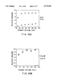
- FIGS. 42A and 42B show the effect of air flow rate on emission from hexane in air arc discharge (31A) and the effect of air flow rate on background emission (31B).
- FIGS. 43A and 43B show the primary voltage effect on emission from hexane in air arc discharge (32A) and the primary coil voltage effect on background emission (32B).
- FIG. 44 shows a sketch of an arc discharge apparatus.
- Arm 593 holds the ground electrode connected to nitrogen flow.
- Arm 591 holds the active electrode and arm 592 is for sample introduction.
- FIG. 45 shows the arrangement that would be used to observe gas-phase infrared emission from a reduced pressure discharge.
- FIG. 46 shows a detection and measurement apparatus of this invention including an electric furnace.
- FIG. 47 shows a detection and measurement apparatus of this invention including a means for excitation by electron impact in a gas discharge.
- FIG. 48 shows a detection and measurement apparatus of this invention including a means for excitation by collisions with a vibrationally excited diatomic molecule.
- the present invention relates to infrared emission detection means and method whereby the infrared emission of excited molecules of interest in a sample is used as a basis for detection of compounds.
- infrared emission is observed as a means of detection for chromatography.
- Organic compounds introduced into an excitation means result in the production of carbon dioxide which allows observation of two strong emission bands over the wavelength range from 1 to 5 ⁇ m.
- Other infrared active species could be produced as well over the entire infrared region.
- Total inorganic carbon and total organic carbon are important analytical parameters in the environmental characterization of water. Total organic carbon determinations are performed routinely as a non-specific measure of the organic content of water in pollution monitoring. Inorganic carbon exists in water as bicarbonate and carbonate ions and as dissolved carbon dioxide. The sum of these carbon species is called Total Inorganic Carbon (TIC). TIC can be determined directly by acidification of the sample to convert bicarbonate and carbonate ions into dissolved CO 2 , purging of the sample with a suitable gas to remove the dissolved CO 2 , and measurement of the CO 2 (usually by infrared absorption). Total inorganic carbon determinations by infrared emission detection can be used in place of alkalinity titrations to determine the amount of inorganic carbonate present in a water sample.
- TOC total organic carbon
- TIC total inorganic carbon
- Infrared emission detection can be used to monitor carbon impurities in electronic grade gases. Carbon/hydrogen characterization of compounds by infrared emission detection is possible by observing the two strong emission bands, one associated with carbon dioxide and one with both water and carbon dioxide. Molecules or molecular fragments containing heteroatoms can be observed by Fourier transform infrared emission spectroscopy. In that many biochemical reactions result in the release of carbon dioxide as a by-product, infrared emission detection can provide the basis for a variety of clinical and biochemical assays.
- the infrared emission detection system finds application in the determination of chloride and available chlorine in aqueous samples.
- the chlorine analysis method includes means for pretreating the sample to evolve chlorine gas. Samples containing aqueous chloride are pretreated with a strong oxidant such as permanganate ion, peroxide ion or MnO 2 thereby forming chlorine gas. Samples containing available chlorine due to dissolved molecular chlorine, hypochlorous acid and/or hypochlorite ion are pretreated with acid thereby rapidly generating molecular chlorine gas. The molecular chlorine gas is then liberated from the sample and reacted with hydrogen to form HCl which is excited to emit a characteristic infrared radiation pattern which is detected.
- a strong oxidant such as permanganate ion, peroxide ion or MnO 2
- the infrared emission detector is a flame infrared emission detector wherein the flame is a hydrogen/entrained-air flame.
- the chlorine gas reacts with hydrogen from the flame to form HCl.
- the HCl is excited by the flame and exhibits a strong, well-resolved emission band which lies between those for water and carbon dioxide.
- a 3.8 ⁇ m bandpass filter in the infrared emission detector is used to monitor the emission band and subsequently determine the concentration of chloride and available chlorine in the sample.
- the performance of the basic infrared emission detector is improved substantially by the use of a dual beam system with background subtraction capability.
- the selectivity ratio and detection limits are optimized by adjusting the detector bias voltage, using an optical filter in the reference channel for background compensation and balancing the Wheatstone bridge network.
- the improved detector can therefore detect smaller quantities of species of interest.
- a preferred embodiment is the use of the improved detector for the detection of carbon compounds, chlorinated compounds, fluorinated compounds as well as chlorofluorocarbons.
- An electrical furnace may serve as an excitation source. Compared to the hydrogen/air flame, a variable-temperature electrical furnace greatly reduces background emission from water vapor and allows emission from the parent analyte in addition to emission from combustion products.
- Electrical excitation means includes electron impact in a gas discharge and excitation by collisions with a vibrationally excited diatomic molecule. This means of excitation does not increase the kinetic energy of the gases involved and emission is achieved at near room temperature.
- the present invention provides an apparatus for detecting and making quantitative measurements of at least one selected component in a sample, in which at least one selected component of the sample, or at least one selected substance produced from the at least one selected component in the sample and characteristic of the at least one selected component, is introduced into an exciting means.
- gas-phase infrared-active molecules emit infrared radiation at at least one characteristic wavelength in proportion to the quantity of the at least one selected component in the sample.
- This first embodiment comprises means for exciting the gas-phase, infrared-active molecules to emit radiation over a given path and infrared discriminating and detector means located on said given path for detecting infrared radiation at the at least one characteristic wavelength and for generating an output signal representative thereof, and thereby determining the quantity of the at least one selected component in the sample.
- the gas-phase infrared-active molecules emit radiation at the at least one characteristic wavelength with an intensity proportional to the quantity of the at least one selected component in the sample.
- the infrared discriminating and detector means may include a wavelength discriminating means located on said path, between the exciting means and the infrared detector means, for allowing the at least one characteristic wavelength to pass from the exciting means to the detector means while inhibiting the passage of other wavelengths, means for separating the wavelengths of the emitted radiation into an infrared spectrum, or a monochromator. Multiple infrared discriminating and detector means may be used in the apparatus.
- the apparatus may further include a computer means, responsive to an output signal from the infrared detector means, for performing signal processing thereon to provide an output indicative of the quantity of the at least one selected component present in the sample.
- the infrared discriminating and detector means may include an interferometer or an interferometer and a computer means, coupled to the interferometer, for performing a Fourier transform analysis on an output signal from the interferometer to thereby obtain a spectral analysis characteristic of the sample.
- the apparatus may include vaporizing means for vaporizing a liquid sample and for conducting the resultant vapors into the exciting means.
- the means for exciting the gas-phase, infrared-active molecules may include furnace excitation, excitation by electron impact in a gas discharge or excitation by collisions with a vibrationally excited diatomic molecule.
- the infrared detector means may include a thermal infrared detector or a quantum detector.
- the at least one selected component or the at least one selected substance may contain carbonates or calcinates, and in that case, the apparatus further includes means for acidifying the at least one selected component or the at least one selected substance to generate CO 2 which is then introduced into the exciting means.
- the at least one selected component or the at least one selected substance may contain carbon-containing compounds, and in that case, the apparatus further includes means for oxidizing the at least one selected component or the at least one selected substance to generate CO 2 which is then introduced into the exciting means.
- the means for oxidizing may be included in the exciting means.
- the at least one selected component or the at least one selected substance may contain hypochlorous acid or hypochlorite ions, and in that case, the apparatus further includes means for acidifying the at least one selected component or the at least one selected substance with HCl to generate Cl 2 which is then introduced into the exciting means.
- the at least one selected component or the at least one selected substance may contain chloride ions, and in that case, the apparatus further includes means for oxidizing and acidifying the at least one selected component or the at least one selected substance to generate chlorine Cl 2 which is then introduced into the exciting means.
- the at least one selected component or the at least one selected substance may include chlorine-containing or fluorine-containing organic compounds, and in that case, the exciting means includes a means for combusting the at least one selected component or the at least one selected substance to thereby generate HCl or HF, respectively, which is then introduced into the exciting means.
- a second embodiment of the present invention is an apparatus comprising means for exciting the gas-phase, infrared-active molecules to emit radiation along a first path, beam splitting means disposed on said first path for directing a portion of the emitted infrared radiation over a second path; first and second infrared detector means located on said first and second paths respectively, first wavelength discriminating means located on said first path between said beam splitting means and said first detector means, and second wavelength discriminating means located on said second path between said beam splitting means and said second detector means, and means connected to the first and second detector means for combining the first and second electrical signals to thereby cause a cancellation of fluctuations in intensity at the at least one characteristic wavelength caused by fluctuations in the background radiation.
- the gas-phase, infrared-active molecules emit radiation at at least one characteristic wavelength with an intensity proportional to the quantity of the at least one selected component in the sample, and the exciting means simultaneously emits fluctuating background radiation along said first path at the at least one characteristic wavelength of the gas-phase, infrared-active molecules and at other wavelengths.
- the first detector means generates a first electrical signal responsive to emitted radiation at the at least one characteristic wavelength
- the second detector means generates a second electrical signal responsive to the simultaneously emitted background radiation.
- the first wavelength discriminating means allows passage of radiation at the at least one characteristic wavelength and inhibits the passage of other wavelengths
- the second wavelength discriminating means allows passage of the emitted background radiation and inhibits the passage of radiation at the at least one characteristic wavelength.
- the means for combining includes means for subtracting the second electrical signal from the first electrical signal.
- This embodiment may further include optical attenuating means, located on the second path between the beam splitting means and the second detector means, for adjusting the level of the second output signal.
- the first and second detector means may be coupled to a biasing circuit means for achieving equalization of the first and second output signals.
- the means for exciting the gas-phase, infrared-active molecules may include furnace excitation, excitation by electron impact in a gas discharge or excitation by collisions with a vibrationally excited diatomic molecule.
- a method for using the first embodiment of the present invention includes the steps of i) exciting the gas-phase, infrared-active molecules to emit radiation, and ii) selectively detecting infrared radiation emitted at the at least one characteristic wavelength and generating an output signal representative thereof, and thereby determining the quantity of the at least one selected component in the sample.
- the method may include the step of discriminating the at least one characteristic wavelength by allowing only the at least one characteristic wavelength to be detected in the detecting step while inhibiting the detection of other wavelengths.
- the discriminating step may include separating the wavelengths of the emitted radiation into an infrared spectrum and may use a monochromator or an interferometer.
- the discriminating step may include use of a computer coupled to the interferometer for performing a Fourier transform analysis on an output signal from the interferometer to thereby obtain a spectral analysis characteristic of the sample.
- the method may further include the step of utilizing a computer for performing signal processing on the output signal produced by said detecting step to provide an output indicative of the quantity of the at least one selected component present in the sample or the step of vaporizing a liquid sample and utilizing the resultant vapors in said exciting step.
- the exciting step may include thermal excitation, excitation by electron impact in a gas discharge or excitation by collisions with a vibrationally excited diatomic molecule.
- a method for using the second embodiment of the present invention includes the steps of i) exciting the gas-phase, infrared-active molecules to emit radiation, ii) splitting the emitted radiation into first and second beams; iii) first detecting radiation in the first beam at the at least one characteristic wavelength, and generating a first electrical signal representative of the emitted radiation at at least one characteristic wavelength, and secondly detecting radiation in the second beam having the emitted background radiation and generating a second electrical signal representative of the simultaneously emitted background radiation; and iv) combining the first and second electrical signals to cancel fluctuations in intensity at the at least one characteristic wavelength caused by fluctuations in the background radiation.
- the first detecting step includes discriminating the at least one characteristic wavelength by allowing passage of radiation at the at least one characteristic wavelength and inhibiting the passage of other wavelengths
- the second detecting step includes discriminating against the at least one characteristic wavelength by allowing passage of the emitted background radiation and inhibiting the passage of radiation at the at least one characteristic wavelength.
- the combining step includes subtracting the second electrical signal from the first electrical signal.
- the method may further include attenuating the second beam to adjust the level of the second output signal. Exciting the gas-phase, infrared-active molecules may occur by furnace excitation, excitation by electron impact in a gas discharge or excitation by collisions with a vibrationally excited diatomic molecule.
- the present invention relates to an infrared detection means and a method for detecting selected molecules of interest in a gaseous sample or samples which can be converted to the gas phase.
- the infrared detection means includes a detector means and a means for exciting molecules of interest in the sample to emit a characteristic infrared radiation pattern.
- heating by a flame is employed to combust and excite the molecules of interest in the sample to produce vibrationally excited molecules such as carbon dioxide which can emit infrared radiation.
- a pre-determined wavelength of infrared radiation emitted by the molecules of interest is observed with a detector that generates an electrical signal in response to the emission at the observed wavelength.
- the observation wavelength is preselected from the characteristic infrared radiation pattern of the molecule of interest.
- the means for isolating a preselected wavelength of infrared radiation is mounted between the exciting and detector means.
- a factor necessary for successful implementation of infrared emission is to achieve a useful level of contrast between the source and the background, that is the source should be at a higher temperature than the surrounding background, and the temperature of the source should be greater than the temperature of the detector. For this reason, one would not expect to see infrared emission from a gas at room temperature if the background and the detector are also at room temperature. Therefore, the first requirement for the successful implementation of this technique is in most cases a means to heat the gas above room temperature. This does not necessarily mean that a flame is required. However, within the limits of molecular stability, the hotter the gases, the greater the radiant emissivity, and the more sensitive the detection system. Since flames typically have temperatures on the order of 1000-3000 K, they represent potentially good emission sources for this application if a low-background flame in the vicinity of the selected emission band can be found.
- excitation means include: 1) other thermal excitation such as a furnace excitation; 2) excitation by electron impact in a gas discharge; 3) excitation by collisions of the second kind with a vibrationally excited diatomic molecule (similar to the mechanism used in the carbon dioxide laser); and 4) photo-excitation with an appropriate source.
- Photoexcitation can be accomplished from the 000 level of CO 2 (resonance excitation) or from the 010 level which is appreciably populated even at room temperature (non-resonance excitation).
- Such infrared fluorescence could be conveniently excited with a carbon dioxide laser emitting radiation at 10.6 ⁇ m. Absorption of such radiation would cause the transition from 010 to 001.
- a second requirement for high sensitivity is the avoidance of the use of any form of solid containment such as a sample cell.
- the infrared emitting source i.e., the gas in this case
- the background As a result of a thermal gradient.
- the emission signal which is initially present from the gas because it is hotter than the walls of the cavity, gradually fades into the background until it disappears.
- a high temperature excitation source is also beneficial in reducing the effects of atmospheric absorption (i.e., telluric absorption when observing CO 2 emission) due to carbon dioxide in the atmosphere.
- atmospheric absorption i.e., telluric absorption when observing CO 2 emission
- various upper level vibrational states become populated, and transitions between upper levels occur.
- the region at 4.4 ⁇ m where the only other carbon dioxide emission occurs is clear of any other potentially interfering flame background.
- the hydrogen/air flame was selected as an excitation source for preliminary studies of flame infrared CO 2 emission.
- the photomultiplier is based on the external photoelectric effect whereby a photon absorbed by a suitable photoemissive material is ejected from the material into the surrounding vacuum. To give the electron sufficient energy to escape the surface of the photoemitter, the photon absorbed must possess an energy greater than the sum of the energy bandgap and electron affinity of the photoemitter. Detectors based on photoemission of electrons as a result of the photoelectric effect can be made very sensitive by the use of electron multiplication with a dynode chain.
- photomultipliers can be made so sensitive that they are often limited by the fluctuation in the arrival rate of photons rather than fluctuations arising within the detector itself.
- the energy requirement for external photoemission is sufficiently large that the use of photomultipliers is confined essentially to the UV/visible region of the spectrum.
- photomultipliers that respond to longer wavelengths beyond the visible (out to about 950 nm) have been produced.
- Detectors which respond to infrared radiation can be classified into two basic categories: thermal detectors and quantum detectors.
- Thermal detectors respond to the heating effect of the infrared radiation and include thermocouples, thermistors, and pyroelectric detectors.
- Quantum detectors make use of the internal photoelectric effect whereby an electron is promoted from the valence band to the conduction band but is not ejected from the material. As a result, these detectors respond out to wavelengths whose energies correspond to the semiconductor bandgap. These detectors include photovoltaic and photoconductive detectors.
- Neither category of detector discussed above employs any form of internal amplification comparable to the photomultiplier and for this reason, IR detectors are less sensitive than detectors commonly used for the detection of UV/visible radiation. Since the major source of noise with these detectors originates within the detector itself and is not due to fluctuations in the radiation field, these detectors are frequently cooled to reduce detector noise, and spectrometers which employ them are termed detector-noise limited
- quantum detectors generally have a higher specific detectivity than thermal detectors, although thermal detectors have the advantage of flat response over a wide wavelength range.
- thermal detectors have the advantage of flat response over a wide wavelength range.
- the lead selenide and indium antimonide detectors were two possibilities. Of the two, the indium antimonide had the higher specific detectivity but generally required cooling.
- the PbSe detector was selected as the most appropriate for preliminary studies on the basis of spectral response and cost. Even with the PbSe detector, however, some thermoelectric cooling may be beneficial to shift the maximum response of the detector to longer wavelengths.
- Process gases are those gases used in manufacturing and electronic-grade gases in particular are those gases used in the manufacture of electronic devices.
- Impurities such as CO, CO 2 , and trace hydrocarbons in gases used in the manufacture of semiconductor devices must be controlled to assure reliable manufacturing conditions. Concentrations of impurities as low as 0.5 to 1 ppmv in nitrogen and argon have been reported to cause difficulties (Whitlock, W. H. et al., 1988).
- FID flame-ionization detector
- a catalyst system using nickel as the catalyst must be employed to convert the CO and CO 2 to methane. The need for the catalytic methanator and complex valving makes the current technology less than ideal.
- the infrared emission detector has good sensitivity to CO, CO 2 , and the light gaseous hydrocarbons. Since the catalytic methanator is not needed, problems with the methanation catalyst and complex valving are not encountered. Furthermore, a continuous-monitoring technique is possible with the infrared emission system. In such a system, three gas streams can be analyzed simultaneously. One stream is fed into a flame directly. This stream measures the total impurity concentration (i.e., CO, CO 2 , and hydrocarbons) (S 1 ). A second stream passes first through a bed of a CO absorbent prior to entering a second infrared emission detector. This stream measures the sum of the CO 2 and hydrocarbons (S 2 ).
- a third stream passes first through a bed of CO 2 absorber (Ascarite) prior to entering a third infrared emission detector.
- This stream measures the sum of the CO and hydrocarbons (S 3 ).
- the signals from the three streams relate to the impurity concentrations as follows:
- the infrared emission system has a multiplex advantage over systems which measure one component at a time.
- infrared emission technology is for water analysis. This includes drinking water (potable water), environmental samples, wastewater, and even clay-based drilling muds used in petroleum production (i.e., oil rigs). This application falls into two major categories: total inorganic carbon- and organic carbon determinations.
- the carbonate concentration is determined indirectly by means of alkalinity titrations.
- the alkalinity of a water sample is determined from the proton condition of the solution as
- K 1 and K 2 are the first and second dissociation constants of carbonic acid.
- the alkalinity of a water sample is also a measure of the acid neutralizing capacity of the solution.
- the total alkalinity of a water sample is determined.
- the total inorganic carbon or C T is determined from a knowledge of the alkalinity by rearranging the alkalinity relationship:
- the alkalinity and the pH of the solution are all that is needed to determine C T .
- there are appreciable amounts of other alkaline materials present which make alkalinity titration data unreliable as a means of determining C T .
- the alkalinity titration is difficult to perform because the indicator endpoint is not sharp.
- potentiometric titrations are performed, the endpoint is still not sharp because the sample is being titrated back to carbonic acid.
- the infrared emission TIC determination is simple, convenient and direct.
- direct it is meant that the infrared emission measures C T directly rather than a property which is related to C T (i.e., the acid neutralizing capacity).
- the use of a direct measurement technique leads to more reliable data on the actual parameter of interest.
- the direct measurement does not require a knowledge of the dissociation constants for carbonic acid to calculate the desired parameter from the measured quantity.
- sulfuric acid 0.5 mL
- a water sample (1 mL) is added to release carbon dioxide gas which is flushed with helium into a hydrogen/air flame.
- the infrared emission from carbon dioxide is measured with an infrared emission detector as described previously.
- a calibration curve prepared from standard carbonate solutions is used to determine the total inorganic carbon concentration in the sample.
- Infrared emission detection is also useful in determining the carbon dioxide content in carbonated beverages such as soft drinks and beer.
- Organic materials in water samples may arise from naturally occurring compounds produced by living organisms or from anthropogenic sources.
- the sum of the naturally occurring organic materials and the synthetic organic materials is referred to as the total organic carbon in the water sample.
- the total organic carbon content of a sample is a non-specific (i.e., doesn't determine the actual individual compounds present) measure of the organic content of the sample.
- Total organic carbon (TOC) determinations are performed on a wide range of samples, including ground water, drinking water, semiconductor process water, municipal wastewater, and industrial wastewater (Small, R. A. et al., 1986).
- Industrial applications of TOC determinations include determination of organic contamination in mineral products such as acids, caustic solutions, as well as aluminum-, nickel-, and cobalt chlorides.
- TOC measurements to determine organic contaminants in cooling water and steam-generation water. Even small amounts of formic- and acetic acid can cause corrosion of turbine blades and heat exchanger equipment (Bernard, B. B., 1985). Since an increase in the organic content of water can be an indication of pollution, TOC determinations have been used to monitor surface water, ground water (i.e., wells), and other water sources for wastewater contamination and industrial effluents.
- TOC determinations are performed by first oxidizing the organic material to carbon dioxide by a variety of methods (Small, R. A. et al., 1986). The carbon dioxide gas generated by this oxidation is then determined by non-dispersive infrared (NDIR) absorption spectrophotometry. Although a variety of NDIR procedures have been employed, a primary problem with absorption measurements is the concomitant absorption by water vapor and acid gases. Partial elimination of the water vapor interference has been achieved through humidity control of the reaction gases flushed into the infrared absorption cell. Because measurements are made in absorption, all TOC analyzers require an infrared emission source to produce the infrared radiation.
- NDIR non-dispersive infrared
- carbon dioxide is produced by the same methods currently used to oxidize organic materials to CO 2 (Lam et al., 1993). These oxidation methods include one or a combination of the following: chemical methods such as the use of peroxydisulfate, heating such as in a furnace with copper oxide and the use of UV radiation. After oxidation, the CO 2 is flushed out of the sample to the infrared emission detector.
- the sample may be combusted directly in the flame to generate CO 2 .
- infrared emission instead of absorption of CO 2 the interference by other concomitants produced by the oxidation process is avoided. Since the infrared emission detector is not affected by water vapor and acid gases, these interferences are absent with the infrared emission TOC analyzer. Since the infrared emission system employs a filter, it falls in the category of non-dispersive infrared analysis (only in emission rather than absorption).
- a carbon to hydrogen ratio instrument is useful for combustion monitoring, as in smoke stack and rocket engine firing monitoring.
- the infrared emission detector is useful as a detector in conventional carbon/hydrogen analyses (as opposed to using it as a detector in chromatography).
- the infrared emission system is used as the detection means in the analysis.
- an instrumental carbon/hydrogen analyzer can use conventional combustion tube techniques to transform the organic material into water and carbon dioxide. The infrared emission is then used to detect the amounts of these materials which have been generated.
- the element chlorine is widely distributed in nature and is used extensively in its various oxidation states.
- the element occurs in nature primarily as the chloride ion (Cl - ) and is one of the major inorganic constituents of surface waters, groundwaters, and wastewaters.
- chloride levels expressed as chlorinity, are approximately related to salinity and can be used to determine the concentrations of all other bio-unlimited elements present in a sample. Chloride concentration is also used as an indicator of water condition.
- chloride concentrations in the sewerage of coastal areas may signal seawater intrusion into the system, while in potable water they are often associated with wastewater contamination.
- chloride concentrations are monitored regularly since elevated levels are generally associated with increased deterioration of metallic pipes and structures, while in cooling water, they are used to indicate the cycles of concentration.
- argentometric methods For the titrimetric determination of aqueous chloride, various argentometric methods exist which use either indicators or potentiometers to detect the endpoint. Alternatively, mercuric nitrate can be used to titrate chloride ion using diphenylcarbazone as an indicator.
- iodometric titration is the method of choice. For chlorine levels less than this amount, amperometric titrations are preferred, but require greater operator skill to avoid loss of chlorine through mechanical stirring. Poor endpoints are also a problem unless the electrodes are properly cleaned and conditioned.
- DPD N,N-diethyl-p-phenylenediamine
- infrared emission detection under high resolution conditions provides spectra wherein the P and R branches of the HCl infrared emission can be easily detected above the flame background in the region from 3200-2400 cm -1 . Since the HCl emission band lies between the water emission band at 3800-3200 cm -1 and the carbon dioxide emission band centered at approximately 2262 cm -1 , the strong, well-resolved infrared emission from HCl should also be useful analytically for the determination of Cl in a variety of chlorine-containing samples (Kubala et al., 1989b).
- any reaction that generates elemental chlorine in a quantitative manner could serve as the basis of an analytical procedure employing flame infrared emission as a highly specific means of detection.
- hypochlorous acid 7.60 at 25° C.
- chlorine refers to the total oxidizing power of the solution due to chlorine, hypochlorous acid and hypochlorite ion, expressed in terms of an equivalent quantity of Cl 2 . (The distribution of Cl between these three species is temperature and pH dependent). Since the following equation
- This application reports the development of a new chlorine-specific method for the direct determination of chloride and available chlorine in aqueous samples based on the principle of infrared emission.
- the flame infrared emission-chlorine analyzer described in Example 4 consists of two commercially available purge devices coupled to a flame infrared emission detector.
- Aqueous chlorine-containing samples are treated chemically to convert the chloride or hypochlorous acid present into molecular chlorine (Cl 2 ) which is then liberated from the sample cell using an inert carrier gas and introduced into a hydrogen/entrained-air flame to produce vibrationally excited HCl.
- a substantial improvement in detection capabilities results when a dual beam system is used as the detector of a flame infrared emission detection method.
- the dual beam system allows subtraction of the background and most importantly the fluctuations in the background (i.e. the noise).
- the signal-to-noise ratio is improved substantially with the use of the improved dual beam system.
- the selectivity ratio and detection limits can be optimized by varying the detector bias voltage, by use of a 3.0 ⁇ m filter for background compensation, an optical attenuation method to balance the bridge network, and a variable bridge resistor.
- FIRE-GC sensitivity has been improved by approximately one to 1.5 orders of magnitude, primarily as a result of changes in burner design (Zhang et al., 1992b).
- the new burner consists of two stainless steel tubes of different diameters, mounted concentrically. Air is introduced through the outer tube, while a mixture of GC effluent and hydrogen gas is introduced through the inner capillary tube. Pre-mixing the analyte with hydrogen promotes uniform, complete combustion and reduces mixing and condensation of analytes in the transport line between the GC column and burner.
- the new burner design requires considerably less hydrogen to produce a stable flame. Consequently, flame water background emission is greatly reduced, and background subtraction is no longer required. Since a beam splitter and other components associated with the background subtraction procedure are no longer necessary, the instrumental complexity of the FIRE radiometer is considerably simplified, and more of the signal can be used for analyte detection.
- the flame supported by this new burner can be made to produce a zone of maximum emission intensity which appears to be concentrated in a smaller volume of space and located directly along the central axis of the burner. If this zone of maximum emission intensity is raised approximately 3 mm above the burner tip, the burner remains relatively cool, and background radiation from blackbody emission is also reduced. Optimization parameters for the hydrogen and air flow rates appear to be the same for all compounds, GC columns (packed and capillary), and injection volumes (0.1 to 2.0 ⁇ L) tested.
- Sensitivity of the new FIRE-GC detector is such that it can be used in conjunction with the smaller injection volumes required by capillary columns, thus permitting improved separation of more complex mixtures.
- the utility of the new FIRE-GC detector was demonstrated by an application involving the separation of a synthetic mixture of 16 compounds on a 15-m silica capillary column under programmed temperature conditions.
- the new burner was shown to respond well to all components of the mixture, including halogenated, non-halogenated, and aromatic compounds, and was also able to detect impurities present in two of the components.
- the nearly perfect peak shapes present in the chromatograms demonstrated the ability of the FIRE-GC detector to respond to compounds with a range of boiling points (36°-152° C.).
- a conservative estimate of detection limits (2 ⁇ ) indicates that the new FIRE-GC detector can respond to 8.6 ng s -1 l of benzene, 9.4 ng s -1 of butanone, 4.6 ng s -1 of 1-chloro-3-methylbutane, and 5.6 ng s -1 of methyl acetate. This represents an average detection limit of 4.5 ⁇ 1.3 ng s -1 in terms of carbon. Response, in terms of ⁇ moles of carbon, was linear over the entire range of concentrations tested, giving an estimated LDR of at least 3.4 orders of magnitude.
- FIG. 1 shows a schematic diagram of the analytical system used in this study. Radiation from the burner was modulated at 569 Hz with the use of a laboratory-constructed chopper, and a lock-in amplifier (Model #3962, Ithaco, Inc., Ithaca, N.Y.) was used to demodulate the chopped signals obtained from the detectors. The output signal from the lock-in amplifier was recorded on a recorder/integrator (Model #3394A, Hewlett-Packard Corp., North Hollywood, Calif.).
- the multichannel FIRE radiometer used in this example employed a direct-reading polychromator (Kubala, et al., 1991) having a spectral bandwidth of 0.15 ⁇ m and equipped with three PbSe detectors.
- the polychromator originally designed (Kubala, et al., 1991) to monitor emission corresponding to H 2 O (2.8 ⁇ m), HCl (3.8 ⁇ m), and CO 2 (4.4 ⁇ m), employed a long-pass filter with a cut-on wavelength of 3.0 ⁇ m for order sorting and attenuation of the water emission at 2.8 ⁇ m. During most of the burner evaluation studies, all three channels were monitored in the unsubtracted mode.
- a gas chromatograph (GC-8A, Shimadzu Scientific Instruments, Inc., Colombus, Md.) with temperature programming capability was used for all chromatographic applications. Analytes were introduced into the chromatograph with conventional microsyringes obtained from standard commercial sources. Injection volumes varied from 0.1 to 2.0 ⁇ L.
- the flow rate for the capillary column was determined by measuring the retention time for CO 2 gas. Separation of the 16-component synthetic mixture was performed with the capillary column, starting at an initial temperature of 40° C. and programmed to rise at a rate of 10° C. min -1 .
- FIGS. 2A and 2B show a schematic diagram of the new burner employed in this example and represents the results of a number of design modifications.
- the burner consists of two metal tubes of different diameters, 202 and 204 mounted concentrically.
- the outer tube 204 was constructed of 4.76-mm (3/16-in.), stainless steel tubing, which was mounted inside a 1.5 ⁇ 1.5 ⁇ 1.5-in. aluminum block 208 using a 1/4-in. NPT to Swagelock connector and held in place by a 1/4 in. to 3/16-in. reducing ferrule.
- the inner tube 202 was constructed of 0.76-mm. (0.03-in.)-diameter stainless steel capillary tubing and was positioned inside the outer tube by a glass wool plug 200 (FIG. 2B). Extension of the inner capillary tube about 1 mm above the outer tube at the burner tip was found to be beneficial in reducing background radiation and improving flame stability.
- the GC column was interfaced directly to the central capillary of the burner through a short segment of stainless steel tubing [1.59 mm (1/16-in.) o.d., 0.51 mm (0.020-in.) i.d.].
- the stainless steel transfer tube was wrapped with heating tape (Part #N-03122-30, Cole Palmer Instrument Co., Chicago, Ill.), and the desired temperature (about 20° to 50° C. higher than the boiling point of the least volatile compound being chromatographed) was maintained by power from a laboratory variac.
- GC effluents were premixed with hydrogen gas shortly after exiting the chromatograph.
- the hydrogen flow rate was controlled by a mass-flow controller (Catalog #2-2834M, Supelco, Inc.), which maintained a constant flow rate within ⁇ 0.3%.
- the top of this T-connector was attached to the outer stainless steel tube of the burner with a 1/4-in. ⁇ 3/16-in. reducing ferrule, and the bottom of the T-connector was attached to a 1/16-in. Swagelock fitting and graphite ferrule, which served to connect the inner stainless steel capillary tube to the transfer tube from the gas chromatograph.
- the total distance between the top of the T-connector and the bottom of the burner was approximately two inches.
- the air flow rate was controlled by a standard gas rotameter (Part #3227-26, Cole-Palmer Co.).
- the burner position (FIG. 1) was located at the focus of the input collection optical system, and the vertical height was adjusted to a position that gave the best compromise between analyte emission band radiance and source background.
- the optimum vertical position for the tip of the burner was employed during chromatographic analysis of the 16-component mixture.
- a delivery system consisting of two concentrically mounted tubes was designed in which hydrogen gas was premixed with carrier gas and analyte in a central capillary tube 202, while air was introduced through an outer tube 204 (FIGS. 2A and 2B).
- This design produced a diffusion flame and ensured that combustion could begin only after the analyte and hydrogen had been able to mix with the oxidant above the burner tip.
- Premixing the analyte with hydrogen had the additional benefit of increasing the linear velocity of gases in the transport line.
- An increase in linear velocity reduced axial diffusion of the eluting analytes (thereby reducing peak broadening), and reduced the partial pressure of the analyte vapor (thereby decreasing the tendency for the analytes to condense during transport to the burner).
- the diffusion flame produced by the concentric, two-tube design appeared to have better stability and much lower noise levels than had been observed with the multiport capillary tube design.
- the diffusion flame could be kept fuel rich and produced a zone of maximum temperature about 3 mm above the burner tip.
- the burner tip With the use of this burner design, the burner tip remained relatively cool (about 100° C.), thereby decreasing the amount of background contributed by blackbody radiation.
- the emission signal proved to be much less sensitive to changes in ambient CO 2 levels than with other burner designs.
- the flame also appears to center the maximum in CO 2 emission intensity in a smaller volume of space along the central axis of the burner.
- This emission profile can be contrasted with that of the diffusion flame produced by the old multiport capillary burner (Hudson and Busch, 1987), in which the emission intensity is more spread out and tends to be concentrated off the central axis of the burner (Ravishankar et al., 1991).
- air flow rate proved to be not particularly critical, and a range from about 100 to 200 mL min -1 was satisfactory. Below 100 mL min -1 , condensation of water around the burner tip was observed, causing the flame to become unstable Above 200 mL min -1 , the combustion rate increased to the point where heating of the capillary tube resulted in unacceptable levels of background radiation. A similar problem was encountered when air was switched to oxygen. The use of pure oxygen lowered the zone of maximum temperature in the flame to a position closer to the burner tip. Even by compensating with a faster hydrogen flow rate, unacceptable heating of the burner resulted.
- FIG. 3 shows a plot of the peak areas obtained in the 4.4- ⁇ m (CO 2 ) channel as a function of hydrogen flow rate for 0.2- ⁇ L injections of a mixture of five compounds, each having a different functional group, onto the 15-m silica capillary column.
- Air flow rate was 100 mL min -1 in all cases, observation height was 3 mm above the top of the inner capillary, and no background subtraction was employed.
- background emission in this channel also increased more or less monotonically with hydrogen flow rate (FIG. 4), and 40-60 mL min -1 of hydrogen appeared to represent a good operating range whenever the silica capillary column was employed.
- FIG. 5 shows a plot of the peak areas obtained in the 4.4- ⁇ m (CO 2 ) channel as a function of hydrogen flow rate for 0.2- ⁇ L injections of a mixture of 4% THF in hexane onto the 6-ft packed column.
- Air flow rate was 100 mL min -1 in all cases, observation height was 3 mm above the top of the inner capillary, and no background subtraction was employed.
- the signal in the CO 2 channel optimized at 60 mL min -1 of hydrogen for both THF and hexane, but because the background emission in this channel also increased monotonically with hydrogen flow rate (FIG. 6), 40-60 mL min -1 of hydrogen appeared to represent a good operating range whenever the packed column was employed.
- FIG. 7 shows a plot of peak areas obtained in the 4.4- ⁇ m (CO 2 ) channel as a function of observation height for 0.2- ⁇ L injections of a mixture of five compounds onto the 15-m silica capillary column.
- observation height refers to the vertical distance between the optical axis of the light collection lens and the tip of the central capillary tube at the top of the burner.
- Hydrogen flow rate and air flow rate were 58 and 100 mL min -1 , respectively, and no background subtraction was employed.
- the signal in the CO 2 channel optimized at approximately 2-3 mm for each of the five compounds.
- background emission in each of the three channels was also a function of observation height. Above 2 mm, background radiation was low and remained relatively unaffected by changes in observation height. Below 2 mm, background radiation increased exponentially as observation height decreased. This rise in background signal can be attributed to the increasing amount of blackbody radiation which comes into the FOV of the detector as the optical axis of the light collection system approaches the capillary tubing and aluminum block.
- FIG. 9 shows a log-log plot of the 4.4- ⁇ m emission intensity vs. the ⁇ moles of carbon for each of the four test compounds. The points representing the two lowest sample concentrations required dilution of the original mixture with pentane, so pentane does not appear in the plot.
- the plot appears to be reasonably linear over the entire range of concentrations ( ⁇ mol C) studied, indicating that the LDR is at least 3.4 orders of magnitude and possibly larger.
- the slope of the least-squares lines through all points was 0.992 (linear regression coefficient, 0.998), indicating uniformly high conversion of all four compounds to CO 2 .
- Detection limits defined as that quantity of analyte required to give an emission signal which was two times the standard deviation of the baseline noise (2 ⁇ ), were calculated for the FIRE radiometer acting as a mass-flow-rate detector (units of ng s -1 ) (Hudson and Busch, 1987), assuming a Gaussian peak shape. The assumption of symmetrical peak shape is approximately valid for the small sample size used in these measurements.
- FIG. 10A shows the FIRE chromatogram obtained for a 0.1- ⁇ L injection of this mixture, with the use of the 4.4- ⁇ m (CO 2 ) channel in the unsubtracted mode.
- the new burner responds well to all 16 components and, therefore, performs well for a number of compound types, including simple straight-chain and branched-chain hydrocarbons, cyclic hydrocarbons, halogenated hydrocarbons, substituted and unsubstituted aromatics, esters, and alcohols.
- the minor peaks (3 and 5 in FIG. 10A) are believed to be an isomer impurity in the reagent grade n-pentane and n-hexane, as suggested by the chromatograms obtained when n-pentane and n-hexane were each injected separately. These two small peaks demonstrate the ability of the FIRE-GC detector to respond to small amounts of impurities present in a sample.
- FIGS. 10B and 10C show FIRE chromatograms obtained with the old multiport capillary burner and represent results obtained for a 1- ⁇ L injection of a 7-component mixture onto a packed column, with the 4.4- ⁇ m (CO 2 ) channel operating in the subtracted (FIG. 10B) and unsubtracted (FIG. 10C) modes.
- the improvement in FIRE-GC sensitivity resulting from the new burner is best demonstrated with n-hexane as an example. Comparing peak 4 in FIG. 10A (3.81 g n-hexane) with peak 6 in FIGS.
- 10B and 10C shows that the sensitivity of the FIRE-GC detector has been improved by approximately one order of magnitude in comparison with the old FIRE-GC detector operating in the subtracted mode and by approximately 1.5 orders of magnitude in comparison with the old FIRE-GC detector operating in the unsubtracted mode.
- the current embodiment for a FIRE radiometer is described in the present example.
- This new prototype instrument incorporates refinements such as an improved burner, an improved optical system and a preamplifier circuit that increase the sensitivity of the instrument compared with that described in parent application Ser. No. 07/415,141.
- the burner is shielded from the environment to reduce sources of drift such as drafts or exhaled carbon dioxide from persons standing in the vicinity of the instrument.
- FIG. 11 The schematic layout for the basic single-channel FIRE radiometer is shown in FIG. 11.
- the radiometer is divided into two chambers 118 and 120.
- Chamber 118 contains the optical components and the detector while chamber 120 houses the microburner that supports the flame.
- a two-tube concentric burner (122) as described in Example 1 is used to support a hydrogen/air or hydrogen/oxygen flame.
- Hydrogen and the analytical sample are mixed together in capillary tube and transfer line 138 and emerge from the central capillary.
- Oxidant either air or oxygen
- transfers line 138 should be as short as possible and should be heated to prevent condensation of high-boiling components in the line.
- the burner is located in chamber 120 of the FIRE radiometer to isolate the flame from drafts produced by the chopper and to prevent flame gases from building up in the inside of the case of the optical section (chamber 118).
- a chimney in the top of the burner chamber serves to prevent the accumulation of flame gases in the burner chamber.
- the burner chamber must be of sufficient size that the flame does not heat the walls of the chamber (which would produce undesirable blackbody radiation that could obscure the gas-phase infrared emission).
- a CaF 2 window 124 in the front of the burner compartment allows radiation from the flame to reach collection mirror 126 in chamber 118 without allowing flame gases to enter compartment 118.
- the burner compartment (120) is flushed with dry He to remove atmospheric carbon dioxide and assist in the removal of flame gases from the chamber.
- the positive pressure produced by the purge gas (He) prevents atmospheric gases from entering chamber 120. Because of the extremely high sensitivity of the FIRE radiometer, the flame must be shielded from atmospheric effects. Without these precautions, carbon dioxide from the breath of persons standing within 5 ft. of the instrument will cause a noticeable increase in the signal that results in significant baseline drift.
- Chamber 118 contains the chopper (128), the collection mirror (126), the bandpass filter (130), the PbSe detector (132), and the preamplifier (134). Radiation from the flame is chopped at approximately 580 Hz by a rotating sectored disk chopper (128) located between the flame and the collection optics (126). A 75-mm diameter front surface spherical mirror (126) with a focal length of 75 mm collects radiation from the flame and focuses an image of the flame onto a lead selenide detector (132). A bandpass filter (130) with a transmission notch selects the desired infrared emission band of the analyte from the other unwanted flame radiation and passes it through to the detector.
- the PbSe detector is mounted directly on a printed circuit board that contains the AC-coupled preamplifier (134) that amplifies the signal prior to its being fed to the lock-in amplifier for demodulation.
- Chamber 118 is tightly sealed with a top and flushed with dry He to remove atmospheric carbon dioxide.
- FIG. 15 shows a schematic diagram of the preamplifier circuit used in this embodiment.
- the basic circuit is an AC-coupled voltage follower with gain.
- a multiple mirror collection optical system such as that described by Busch et al., Applied Spectroscopy 45:964-968 (1991) can be employed for the purpose of increasing the solid angle of radiation collected by the detector.
- mirrors M 1 , M 2 , and M 3 in FIG. 1 of the aforementioned reference would be located in chamber 120.
- Spherical mirror M in chamber 118 would replace the lenses L 1 and L 2 in FIG. 1 of the reference.
- a reference detector such as described in Example 5 to reduce the effects of flame flicker and flame drift.
- Said reference detector would consist of a second PbSe detector with a bandpass optical filter that transmits radiation corresponding to the water background from the flame (for example, radiation at 3.0 ⁇ m).
- Said reference detector could be located in chamber 118 (just after the chopper) in close proximity to the flame so as to view the flame directly without the need for optical focusing components. This detector would be placed off axis to the window to view the flame directly without obscuring the field of view of the flame by mirror 126.
- the optical system of the embodiment described in this example is simpler and superior in performance to the lens systems used in previous FIRE embodiments.
- the CaF 2 lenses used in previous embodiments had a limited transmission range and suffered from optical aberrations that severely degraded the image of the flame produced on the detector. This poor imaging ability resulted in radiation from the hot burner tip and less desirable regions of the flame reaching the detector and increasing the background to unacceptable levels.
- the spherical mirror used in this embodiment will transmit radiation over the entire infrared spectrum.
- the use of a spherical mirror under conditions of small angles of incidence produces a very high quality image of the flame on the detector.
- use of a 3 in diameter (75 mm) spherical mirror with a 75 mm focal length results in an f/1 optical system with high collection efficiency.
- Wavelength isolation with an optical bandpass filter has been accomplished in two ways in the present embodiment.
- the mounting bracket that holds the PbSe detector has been machined so that a standard 1 in (25 mm) bandpass filter is held in a circular depression in front of the detector by means of an O-ring.
- the filter can be incorporated in the TO-5 case that houses the detector.
- the optical bandpass filter replaces the standard sapphire window used by the manufacturer.
- Detectors with integral bandpass filters built in can be obtained directly from the detector manufacturer (Cal-Sensors, Santa Rosa, Calif.) upon request by specifying the desired transmission band of the filter.
- This arrangement reduces the number of surfaces through which the infrared radiation must travel and is substantially cheaper to employ because more efficient use can be made of the filter material.
- a standard 1 in filter (approximate cost $600) can be cut into many smaller pieces by the detector manufacturer so that is can be used with many detectors.
- integral filters for example, with a transmission band at 4.4 mm
- cooled detectors can be used with the FIRE radiometer in place of the room temperature detectors that have been employed.
- Thermoelectrically cooled PbSe detectors are commercially available. Cooling extends the long wavelength response and increases the specific detectivity (D ) of the detector.
- other emission sources can be used with the FIRE radiometer described above. Such sources include electrically heated furnaces (Example 6) and various types of electrical discharges (Example 7).
- the FIRE radiometer described above has been used as a detector for gas chromatography.
- a Shimadzu GC-8A gas chromatograph (Shimadzu Scientific Instruments, Columbus, Md.) equipped with a 15 m ⁇ 0.53 mm SPB-20 silica capillary column (Supelco, Ballafonte, Pa.) was used. Detection limits for benzene obtained with this system were 800 pg s -1 . (A picogram is 10 -12 g.)
- a miniature capillary-head burner (Hudson and Busch, 1988) was modified for use with liquid samples. As the previously designed burner was intended to admit a gas stream from the gas chromatograph to the center of the burner-head, the burner was modified for nebulized liquid samples. The central sample injection capillary was removed, and the number of small-bore capillary tubes in the burner-head was increased from 6 to 19 (the internal diameter of the capillary tubes was 0.6 mm). The overall diameter of the burner orifice was 0.5 cm.
- the capillary-head burner was fitted with a Jarrell-Ash model X-88 atomic absorption cross-flow nebulizer and a 3 cm long ⁇ 4 cm diameter TEFLON spray chamber. The nebulizer and spray chamber were coupled to the burner body by boring a one inch hole in the side of the burner body (perpendicular to the capillary-head) and press fitting the spray chamber/nebulizer assembly to the burner.
- a 1:1 hydrogen/air flame stoichiometry was used for all measurements, and the fuel and oxidant flow-rate were maintained at 200 mL/min.
- a 1:1 fuel/oxidant mixture resulted in a stable flame approximately 4 cm in height by 1 cm in width.
- the infrared emissions were observed over a 0.6 cm vertical segment centered at a height of 1.5 cm from the burner top.
- the reagent grade liquid samples were introduced into the flame via aspiration by the nebulizer.
- Fourier transform infrared emission spectroscopy allows multiwavelength analysis.
- the Fourier transform spectrometer by virtue of the multiplex nature of the data acquisition, is a multichannel instrument and can therefore monitor all infrared wavelengths simultaneously. Since the desired molecular emission occurs in the infrared spectral region, any standard, commercially available Fourier transform-spectrometer can be utilized without the need for special optics, beamsplitters, or detectors.
- the Fourier transform instrument also provides several advantages for infrared emission spectroscopy. These advantages include: a single instrument for both elemental and molecular analysis, high optical throughput, good spectral resolution, accurate wavelength recording due to the reference laser, the ability to signal average by coaddition, and the capability of performing spectral subtraction.
- FIG. 16 schematically shows the arrangement of the burner 310, mirror 312 and Fourier transform-spectrometer 314 for Example 3.
- a 5-cm-focal-length, 10-cm-diameter aluminum mirror 312 was used to collect and collimate the infrared emissions from the flame. It should be noted that the infrared collection mirror 312 was placed off the optical axis by approximately 30 degrees. No significant aberrational defects were observed.
- the hydrogen/air flame was chosen to excite the molecules of interest in order to eliminate carbon dioxide emissions from the fuel gases. Otherwise, the determination of carbon, as carbon dioxide, would be significantly impaired.
- FIGS. 17-22 are characteristic infrared emission spectra for carbon tetrachloride, methanesulfonyl fluoride, the H 2 /Air flame background, methanol, trichlorotrifluoroethane and tetramethylsilane. These spectra clearly show that bands other than those from H 2 O and CO 2 can be observed in the flame.
- the chlorine sensitive flame infrared emission detection instrument is shown in FIG. 23.
- the instrument consists of a chlorine generation and liberating apparatus and a flame infrared emission detection system.
- the chlorine generation and liberating apparatus contains two purge devices 387 and 388 (model #991710, Wheaton Scientific, Millville, N.J.) connected together in parallel using 3.2 mm o.d. polyethylene tubing and two, three-way valves (model #B-42XS4, Whitey Co., Highland Heights, Ohio) as described in Kubala et al., Anal. Chem., 1989, Vol. 61 pgs. 1841-1846, incorporated herein by reference.
- One of the purge tubes serves as the sample chamber 387 while the second serves as the reference chamber 388.
- Each purge device consists of a 5-mL demountable tube that can be disconnected for sample introduction and cleaning.
- a septum 381 located at the top of each purge tube allows the samples and reagents to be introduced by syringe (sulfuric acid syringe: model #2300, Becton-Dickson & Co., Rutherford, N.J.; KMnO 4 syringe: model #1001, Hamilton Co., Reno, Nev.; water sample syringe: model #1002, Hamilton Co., Reno, Nev.).
- syringe sulfuric acid syringe: model #2300, Becton-Dickson & Co., Rutherford, N.J.
- KMnO 4 syringe model #1001, Hamilton Co., Reno, Nev.
- water sample syringe model #1002, Hamilton Co., Reno, Nev.
- Helium gas maintained at a flow rate of 130 mL/min, was used to purge evolved Cl 2 from the aqueous solutions into the flame 382 of the flame infrared emission detector.
- the optimum flow rate of hydrogen in the capillary-head burner 383 was determined to be 324 mL/min with combustion supported only by entrained air.
- the supply pressures of the helium and hydrogen were regulated at 0.75 atm using triple-stage regulation 389.
- the optical system of the flame infrared emission detector was modified from that described in Kubala et al., Anal. Chem., 1989, Vol. 61, pgs. 1841-1846 by the addition of a 5-cm-focal-length, f/1 concave mirror 384 (Model #44340, Oriel Corp., Stratford, Conn.) installed behind the hydrogen/air flame.
- This back collection mirror 384 in conjunction with the CaF 2 lens 385, directed the infrared emission from the flame onto the PbSe detector 386.
- the flame infrared emission detector was also modified by replacing the 4.4 ⁇ m CO 2 optical bandpass filter described in Kubala et al., Anal. Chem., 1989, Vol. 61, pgs. 1841-1846, with a 3.8 ⁇ m optical bandpass filter 391 (Model #S-902-079, Spectrogon, Secaucus, N.J.) to spectrally isolate a portion of the HCl emission consisting of most of the more intense part of the R branch.
- This optical bandpass filter 391 possessed a full-width at half-maximum height (FWHM) of 0.18 ⁇ m and was placed immediately in front of the detector 386.
- the flame infrared emission was detected using a PbSe photoconductive cell operated at room temperature with a bias potential of 45 V.
- the detector preamplifier circuit, lock-in amplifier and recorder/integrator have been previously discussed in Kubula et al., Anal. Chem., 1989, Vol. 61, pgs. 1841-1846 except for a slight change in the preamplifier circuit to allow for a larger bias voltage.
- a stock solution of 100 mM NaCl (Mallinckrodt, Inc., St. Louis, Mo.) was prepared by dissolving NaCl, dried at 120° C. for 24 hours, in deionized water. Standard NaCl solutions, having concentrations of 0.1, 0.5, 1.0, 2.0, 5.0, 8.0, and 10 mM, were prepared before use by diluting aliquots of the stock solution to the appropriate volumes.
- a saturated solution of KMnO 4 (Mallinckrodt, Inc., St. Louis, Mo.) used in conjunction with concentrated H 2 SO 4 (Mallinckrodt, Inc., St. Louis, Mo.) served as the oxidizing agent for the aqueous chloride determinations.
- the saturated KMnO 4 solution was boiled and filtered to remove any MnO 2 that might be present.
- Aqueous solutions of AgNO 3 Thorn Smith, Inc., Beulah, Minn.
- Na 2 S 2 O 3 Sargent-Welch Scientific Co., Skokie, Ill.
- the flame in the flame infrared emission system was ignited, and the instrument was allowed to warm up until a stable baseline was obtained on the chart recorder. As part of the warm-up procedure, He purge gas was directed through the dry reference purge tube and into the flame. When the instrument had stabilized, the analysis for aqueous chloride or available chlorine was carried out according to the appropriate procedure indicated below.
- the sample purge tube 387 was disconnected, a 1.0-ml volume of an aqueous chloride standard was placed on the glass frit 392, and a 0.5-mL volume of concentrated H 2 SO 4 was added using a syringe.
- the purge assembly was then reconnected, and the He flow was switched from the reference purge tube 388 to the sample purge tube 387 using the dual, three-way valve system.
- the acidified standard solution was purged for approximately 70 seconds.
- a 0.1-mL aliquot of the saturated KMnO 4 solution was injected through the septum 381 and into the sample chamber using a syringe.
- the chlorine gas produced from the resulting oxidation of the aqueous chloride in the sample was liberated from the solution and introduced into the flame where it formed vibrationally excited HCl.
- the flame infrared emission detection system used in this experiment for the determination of chloride and available chlorine is similar to the system which has been previously described for use in total inorganic carbon (TIC) determinations in Kubala et al., Anal, Chem., 1989, Vol. 61, pgs. 1841-1846.
- TIC total inorganic carbon
- FIGS. 24A-24C The spectra shown in FIGS. 24A-24C were obtained on a Mattson Cygnus 100 Fourier-transform infrared spectrometer.
- FIG. 24A is a transmission spectrum of the bandpass filter used in the flame infrared emission detector (maximum transmission at 3.8 ⁇ m 75% T, 0.10% elsewhere).
- FIG. 24B is a flame infrared emission spectrum from a hydrogen/entrained-air flame containing hydrogen chloride wherein the strong HCl stretching vibration is centered at 2900 cm -1 .
- FIG. 24C is a flame infrared emission spectrum from a hydrogen/entrained-air flame in the absence of hydrogen chloride showing the background emission from water.
- FIG. 24B The resolution conditions are sufficient to reveal the rotational fine structure associated with the P- and R-branches of the HCl emission band (FIG. 24B).
- FIG. 24A the 3.8 ⁇ m bandpass filter optically isolated the 3.64-4.03 ⁇ m portion of the R-branch of the HCl emission band.
- the corresponding flame background spectrum FIG. 24C
- FIGS. 24A and 24C show that this region of the spectrum should be ideal for the detection of hydrogen chloride.
- FIGS. 24A and 24C also indicates that a filter with a somewhat wider bandpass could have been used and would have been desirable from the standpoint of enhancing the total HCl emission received by the PbSe detector.
- the filter selected for this study possessed the widest spectral bandpass in this region of any which were commercially available.
- the water emission bands occurring within the bandpass of the 3.8 ⁇ m HCl filter are relatively weaker (FIG. 24C) and produce a background signal approximately 12 times lower than in the case of CO 2 detection. Since the intensity of the HCl infrared emission band transmitted through the 3.8 ⁇ m optical filter is also weaker in comparison to the intensity of the CO 2 infrared emission band transmitted through the 4.4 ⁇ m optical filter, a detector-noise-limited situation was encountered, i.e. the noise amplitude was independent of the flame.
- the detector bias voltage was increased from 30 V to 45 V in order to enhance the detectivity of the PbSe detector (Infrared Detectors; Hamamatsu Photonics, K. K., Solid State Division; 1126 Ichinocho, Hamamatsu City, 435, Japan, February 1985).
- a back collection mirror 384 (FIG. 23) was added behind the burner 383 to increase the light throughput of the optical system. The location of this mirror 384 was determined experimentally by adjusting the mirror position until the signal from the flame background water emission was maximized at the detector. Use of the mirror 384 enhanced the light throughput by a factor of 2.5. Both of these modifications resulted in improved SNR's and lower detection limits.
- the purging apparatus (FIG. 23) consisted of two separate chambers, one for sample introduction and chlorine generation, and a second which served as a reference. Two, three-way valves permitted the He purge gas flow to be switched from one chamber to the other between sample determinations.
- degassed water was used in the reference purge tube 388 to maintain a constant flow of He saturated with water vapor to the flame.
- Cl 2 gas due to the corrosive nature of Cl 2 gas in the presence of water, it was found necessary to flow dry He through the reference chamber and the sample introduction system between sample determinations. This removed residual moisture from the walls of the sample introduction system and reduced corrosion of the burner and plugging of the sample introduction capillary. Therefore, in contrast to the flame infrared emission-TIC procedure, the flame infrared emission-Cl procedure employed a dry reference purge tube 388.
- the flame infrared emission system functions as a mass flow-rate detector (Hudson and Busch, 1988)
- the intensity of the signal arising from the vibrational excitation of HCl in the hydrogen flame is a function of both the He flow rate and hydrogen/air ratio.
- higher He flow rates resulted in increased peak heights and therefore increased signal-to-noise ratios, a practical upper limit was reached when the sample was forced out of the purge tube.
- a He flow rate of 130 mL/min was determined to represent the best compromise condition for maximizing signal-to-noise ratio without sample loss.
- a fuel-rich flame was expected to enhance HCl emission and improve detection limits.
- a pure H 2 flame supported only by entrained air, afforded SNR's that were approximately 2.5 times greater than those obtained under fuel-lean flame conditions.
- the chloride ion To perform chloride determinations using the flame infrared emission system, the chloride ion must first be oxidized to chlorine gas in the sample chamber.
- the generation of chlorine gas from aqueous chloride samples requires a suitable oxidizing medium.
- the oxidizing agent To be satisfactory for use with the flame infrared emission detector, the oxidizing agent must meet two basic requirements. First, it must have a reduction half-cell potential sufficient to oxidize chloride ion to chlorine (in excess of +1.36 volts under standard conditions). Second, the kinetics of the oxidation must be fast. If generation of chlorine gas does not proceed rapidly, broad peaks will be obtained which adversely affect the sensitivity of the system.
- the total time required for signal acquisition from an aqueous sample was approximately 3.5 min (from initial acid injection to purge tube disconnection and clean-up).
- good peak profiles were obtained (FIG. 25A-25B).
- the hydrogen chloride signal profiles shown in FIG. 25A were obtained by treatment of an acidified 1.0 ml aliquot of 8.00 mM NaCl solution with saturated KMnO 4 and those shown in FIG. 25B were obtained by the addition of concentrated sulfuric acid to a 0.1 ml aliquot of acidified bleach sample, diluted 20-fold (4.0 ⁇ moles available chlorine).
- the reproducibility of the flame infrared emission procedures was studied by recording the signals from oxidizing eight 1.0-mL aliquots of a 5 mM NaCl standard.
- the relative standard deviation (RSD) was determined to be 3.34% for peak height measurements and 5.08% for peak area measurements.
- the difference in reproducibility between the peak height measurements and the peak area measurements most probably occurs in the trailing edge of the peak profile as discussed by Kubala et al, Anal Chem., 1989, Vol. 61 pgs. 1841-1846.
- Calibration curves were prepared by oxidizing 0.10 to 10 mM NaCl standards and were found to be linear (correlation coefficient of 0.9997).
- the linear regression equation for a typical calibration curve possessed a slope of 11.46 mm/mM and a y-intercept of -0.09 mm.
- the detection limit for Cl - with the flame infrared emission-chlorine system defined as a concentration of Cl - producing a signal equivalent to twice the rms noise, was found to be 1.59 ppm (4.49 ⁇ 10 -2 mM Cl - ).
- the detection limit for available Cl 2 based upon the Cl - calibration curve (and defined at twice the rms noise), was found to be 1.61 ppm (2.26 ⁇ 10 -2 mM Cl 2 ).
- Natural water and oil brine samples were used to evaluate the analytical performance of the flame infrared emission-chlorine system for the determination of aqueous chloride.
- the natural water samples included tap water from the Texas cities of Waco and Hewitt, surface waters from Lake Brazos, the Bosque and Brazos River, and brine samples from oil-bearing rock formations.
- the brine samples were obtained from the Van oil field located in Northeast Texas [Woodbine formation (975 m) and Nacitoch formation (366 m)] and were separated from the associated crude oil by slight heating (80° C.) and centrifugation. A 200-fold dilution of these brine samples was necessary in order to provide a concentration in the linear range of the calibration curve.
- Table 3 compares the chloride values determined by argentometric titration using potassium chromate as an indicator with chloride values obtained using the flame infrared emission detector. Each measurement in the table is an average of four replications. Although the tap water samples used in this study were chlorinated, the concentrations of available chlorine as determined by iodometric titration were below the detection limit of the flame infrared emission detector. As a result, no interference from available chlorine was encountered in the determination of chloride ion for the tap water samples used in this study.
- Table 4 compares the results obtained for available chlorine by iodometric titration with those obtained using the flame infrared emission detector and shows that the average precision obtained using the flame infrared emission detector is quite good (RSD 1.84%). Taking the iodometric titration as a reference method, the average relative error for the three bleach samples is 2.97%. The close agreement between available chlorine as determined by the flame infrared emission detector and as determined by iodometric titration demonstrates the feasibility of using chloride to prepare the flame infrared emission calibration curve.
- Interferences with the flame infrared emission-chlorine analyzer can be classified into two major types: chemical and spectral. Spectral interferences in the flame infrared emission detector will occur whenever purgeable contaminants present in the sample are capable of existing as stable molecules or fragments at flame temperatures and emitting infrared radiation within the bandpass of the filter. Because of the specificity of infrared emission and the judicious selection of notch filters, however, the chance of severe interference (i.e., direct overlap) is not particularly likely.
- Interference filters of the type used in the flame infrared emission-chlorine analyzer have a small, but finite, transmittance at wavelengths well removed from the peak transmission wavelength.
- the filter used in this study for example had a 0.1% transmittance in the vicinity of the 4.42 ⁇ m CO 2 emission band. While this transmittance seems small, optical leakage of the CO 2 band can produce measurable signals in the presence of large amounts of carbon-containing interferents.
- Chemical interferences can occur with the flame infrared emission-chlorine analyzer in a number of ways, such as altering the oxidation process (in the case of chloride) or retarding the purging of chlorine (Cl 2 ) from the sample chamber.
- any concomitant which produces a volatile chlorine-containing compound that either does not burn readily in the flame or does not form HCl as a combustion product will depress the signal.
- Chemical interference can also occur if a non-volatile chlorine-containing compound is produced instead of Cl 2 or if a purgeable contaminant reacts with Cl 2 in the purge gas stream and reduces the amount of Cl 2 reaching the flame.
- Bromide, iodide, and phosphate can introduce positive errors in the determination of chloride ion by argentometric titration. Since these anions can be present in natural waters at concentrations as high 1 mg/L [Br], 0.1 mg/L [I], and 0.4 mg/L [P] (Greenburg, A. E. et al., 1985; Manahan, S. E., 1979), the effect of these species as possible interferences in the determination of aqueous chloride using the flame infrared emission system was investigated.
- chloride determinations were repeated using 5 mM NaCl standards which had been spiked with bromide, iodide, and phosphate significantly greater than the maximum concentration expected for natural waters. The signals obtained from the spiked solutions were then compared to an unspiked 5 mM NaCl standard.
- Table 5 shows that the presence of bromide, iodide, or phosphate resulted in a large positive error in the argentometric titration method, with the apparent chloride concentration being given by the sum of the true chloride concentration (175 ppm) and the concentration of the interfering anion, expressed at its chloride equivalent (about 21 ppm). Although no observable difference in peak height occurred in the presence of iodide and phosphate for the flame infrared emission detector (Table 5), a 27% suppression of the HCl signal occurred in the presence of bromide. In order to quantify this effect, 5 mM NaCl solutions having different bromide concentrations were prepared and analyzed.
- the flame infrared emission-chlorine procedure is capable of detecting available Cl 2 in aqueous samples. Since many municipalities add Cl 2 or a chlorine-containing compound (chloramines) to tap water for disinfection, available chlorine may interfere in the determination of aqueous chloride. Thus, the initial purging step of the acid/sample mixture before oxidation of the aqueous chloride is useful in removing any available Cl 2 that may be present in the water sample.
- Carbon dioxide can be present in the flame as a result of purging CO 2 from an acidified carbonate-containing solution as in Kubala, et al, Anal. Chem., 1989, Vol 61. pgs. 1841-1846 or combusting a purgeable organic compound as in Example 1. Because the transmission characteristics of the 3.8 ⁇ m HCl bandpass filter allow for slight filter bleed in the region of the CO 2 infrared emission band [centered at 4.42 ⁇ m], carbonates and purgeable organics could act as spectral interferences in the determination of aqueous chloride and available chlorine.
- the flame infrared emission detection system described in this experiment has been shown to be a sensitive, reproducible, accurate, and direct means of determining chloride in water and available chlorine in liquid bleach. It is easy to use and requires only a one-milliliter sample for each determination. In its present stage of development, the time required for signal acquisition from a sample is 3.5 minutes from the sample injection to purge-tube disconnection and clean up. The system is easily amenable to automation, and a multiple purge-tube version is envisioned.
- the schematic layout for the dual channel flame infrared emission detector is shown in FIG. 27.
- the detection system consists of an optical dual channel module, followed by the electronic signal processing module.
- the dual channel optical arrangement is made up of a flame excitation source 421 (Hydrogen/air combustion flame), collimating lens 422, focusing lenses 423 and 424, mirror 425, zinc selenide beam splitter 426, mechanical light beam chopper 427 (for signal modulation), and optical band pass filters 428 (for spectral band isolation).
- a flame excitation source 421 Hydrogen/air combustion flame
- collimating lens 422 focusing lenses 423 and 424
- mirror 425 zinc selenide beam splitter 426
- mechanical light beam chopper 427 for signal modulation
- optical band pass filters 428 for spectral band isolation
- the light from the source 421 is collimated by a calcium fluoride lens 422 of focal length 5 cm (P#43150, Oriel Corporation, Stratford, Conn.), and the mirror 425 of focal length 2.5 cm (P#44350, Oriel Corporation, Stratford, Conn.).
- the collimated radiation is then modulated at a frequency of 570 Hz by a mechanical light beam chopper 427 (designed and machined locally in this lab).
- the modulated radiation is then passed through a zinc selenide beam splitter 426 (P#45360, Oriel Corporation, Stratford, Conn.), which serves the role of a beam splitter dividing the radiation in two portions.
- Each portion of the divided radiation is then focussed onto a 1 ⁇ 5 mm lead selenide detector 429 (P#P791, Hamamatsu Corporation, Bridgewater, N.J.) by calcium fluoride lenses 423 and 424 of focal length 5 cm (P#43150, Oriel Corporation, Stratford, Conn.).
- Optical band pass filters 428 were placed in front of the detectors for isolating the spectral bands of interest.
- the filters 428 used were (1) 3.0 ⁇ 0.03 ⁇ m narrow band pass filter (P# 58160, Oriel Corporation, Stratford, Conn.), (2) 4.4 ⁇ 0.03 ⁇ m narrow band pass filter (P#58300, Oriel Corporation, Stratford, Conn.), (3) 3.8 ⁇ 0.03 ⁇ m narrow band pass filter (P#58230, Oriel Corporation, Stratford, Conn.), (4) 2.35 ⁇ 0.01 ⁇ m narrow band pass filter (P#NB-2350-052-B Spectrogon, Secaucus, N.J.), (5) 2.5 ⁇ 0.05 ⁇ m short pass filter (P#SP-2550-S Spectrogon, Secaucus, N.J.).
- One half of the divided optical path serves as the reference channel for monitoring the source background fluctuations, and the other half as the analytical channel for monitoring the analytical signals of interest.
- the 3.0 ⁇ m filter was placed in the reference channel to monitor and compensate for the background fluctuations in the flame due to H 2 O emission from the flame.
- the 4.4 ⁇ m notch filter to isolate the CO 2 emission band
- the 3.8 ⁇ m notch filter to isolate the HCl band
- 2.35 ⁇ m notch filter in combination with the 2.5 ⁇ m short pass filter to isolate the HF band
- the additional short pass filter was necessary, to effectively isolate the HF band from the strong interference band at 3.0 ⁇ m due to background emission from H 2 O present in the flame.
- the pre-amplifier circuit configuration for the dual channel system is shown in FIG. 28.
- the lead selenide detectors 431 and 432 were biased at +70 volts from a regulated dc power supply (P#6516, Hewlett Packard, Avondale, Calif.).
- the biasing circuit was tied together to the common power supply to achieve the classical Wheatstone bridge configuration.
- the value of the matching load resistors (300k) 434 and 435 for biasing the lead selenide detectors were chosen based on the manufacturer's specification sheet.
- a 20K ohm multiturn trimmer potentiometer 433 was connected in series with the resistor 434, which along with the detector 431 constitute the reference arm of the Wheatstone bridge network.
- the potentiometer 433 was used to fine tune the zero adjustment of the Wheatstone bridge to achieve an accurate balance condition.
- the voltages, V Ri and V Ai developed at the junctions R and A respectively were amplified separately by the pre-amplifier circuits.
- the pre-amplifier circuit configuration of the reference and analytical channels are identical in all respects (in terms of the values of the resistor and capacitors, and the operational amplifiers used).
- a BIFET operational amplifier (TL 071, Texas instruments, Dallas, Tex.) was used.
- the operational amplifiers were powered from a standard regulated ⁇ 15 V dual dc power supply (P#2718, Heath Co, Benton Harbor, Minn.).
- V Ro and V Ao were then connected separately to the B and A input of the lock-in amplifier (Ithaco, 3962 single phase lock-in amplifier, Ithaca, N.Y.).
- the differential input mode (A-B) of the lock-in amplifier was chosen for operation. Under these conditions the output of the lock-in amplifier is also the differential output, i.e. V Ao -V Ro .
- the signal from the analytical channel was connected to the A input of the lock-in amplifier which was operated in the single ended input mode. After proper phase setting and time constant adjustment, the approximate value of the signal was recorded.
- the analytical channel signal was disconnected from the lock-in amplifier input and the reference channel signal was connected.
- the reference channel signal level was approximately 50 times greater than the analytical channel signal level.
- the signal level to the reference channel was attenuated optically with an iris diaphragm 420 placed in front of the lens 424. The aperture width of the iris was adjusted until the signal level in the reference channel was approximately the same as in the analytical channel.
- the analytical channel signal was then re-connected back to the A input of the lock-in amplifier and the reference channel signal was then connected to the B input of the lock-in amplifier.
- the differential input mode (A-B) of the lock-in amplifier was chosen for operation.
- the aperture width was then adjusted further until the output of the lock-in amplifier was approximately zero. Finer zero adjustments were made with the help of the trimmer potentiometer 433.
- the output of the lock-in amplifier was connected to a recorder/integrator (P#HP3394A, Hewlett Packard, Avondale, Calif.) for subsequent data processing.
- a Shimadzu Gas chromatograph (model GC-8A, Shimadzu Instrument Inc., Columbia, Md.) with a thermal conductivity detector and temperature programming capability was used throughout this work.
- the outlet of the column was interfaced to the burner body of the flame infrared emission detector by the method already described (Hudson and Busch, 1988).
- the design and construction of the burner are as described (Hudson and Busch, 1988).
- the stainless steel capillary interface tube was wrapped with a heating tape and the temperature of the heating tape was maintained at 250° C. This was necessary to prevent the column effluent from condensing in the interface tube.
- the capillary burner head supported a hydrogen-air combustion flame.
- the H 2 and the air flow rates to the burner were regulated by means of standard flow meters (P#3227-20 (for hydrogen) and P#3227-26 (for air), Cole Parmer Company, Chicago, Ill.).
- the gas chromatographic column used throughout this work was a 6 ft ⁇ 1/8" SP alloy column packed with carbopack-B and 5% Fluorcol. (P#12425, Supelco Inc., Bellafonte, Pa.). This column is specially designed for separation of fluoro and chloro carbons.
- Helium was used as the carrier gas throughout and a flow rate of 30 mL/min was used.
- the liquid samples were introduced into the gas chromatograph by means of standard Hamilton microliter syringes. All the optical components were mounted on aluminum blocks designed and machined locally.
- the aluminum mounts were painted flat black to minimize stray radiation and reflections reaching the detector.
- a shield made of aluminum and painted flat black on both the inside and the outside was placed around the burner to minimize flame flicker due to air currents from the atmosphere and the chopper blade. All experiments were performed after a 30 minute warm-up period to allow for the stabilization of electronic components and lead selenide detector response.
- Freon-113 was used to evaluate the response of the system in the fluorine- and chlorine-selective modes of operation.
- Pentane was used as the hydrocarbon comparison standard for evaluation of selectivity ratios of the fluorine and the chlorine modes of operation, since pentane does not produce any HCl or HF on combustion. Typical selectivity ratios and detection limit calculations are shown in Table 7 for the fluorine selective mode of operation.
- the Wheatstone bridge configuration for implementing the background compensation has already been discussed.
- the bridge balancing condition was actually achieved by two different methods and the relative performances of these methods were evaluated with the two parameters i.e. selectivity ratio, and detection limits.
- the two methods compared are (1) optical attenuation and (2) electronic attenuation. A brief discussion of these two methods is presented in the following section.
- the Wheatstone bridge network used for the optical attenuation method is shown in FIG. 28. This method has already been discussed. The bridge balance condition was achieved (under the flame background conditions) by optically attenuating the signal intensity in the reference channel by means of an iris diaphragm, until it approximately equaled the signal in the analytical channel. Under these conditions any fluctuations in source intensity common to both channels would mutually cancel each other and only signals due to species of interest would appear in the analytical channel.
- the electronic attenuation method could further be classified into (1) an adjustable load resistor method and (2) an adjustable pre-amplifier gain method.
- the Wheatstone bridge network used in the adjustable load resistor method is shown in FIG. 30.
- the bridge balance (under the flame background conditions) was achieved by adjusting the value of the resistance of the load resistor 451 on the reference arm of the bridge.
- the load resistor 451 and the lead selenide detector 453 constitute the reference arm of the Wheatstone bridge.
- the load resistor 451 on the reference channel is a multiturn trimmer potentiometer whose value could be adjusted until the potential at points R and A are approximately equal. Under these conditions the signal levels V Ri and V Ai are equal and the differential output (V Ao -V Ro ) is zero.
- the Wheatstone bridge network used in the adjustable preamplifier gain method is shown in FIG. 31. It is essentially the same as used in the previous method, shown in FIG. 30, the only difference being that the signal levels V Ao and V Ro are made equal by adjusting the gain of the reference preamplifier circuit with a gain control resistor 465. The gain of the reference channel circuit was adjusted until the signal level V Ro became equal to V Ao . Under these condition the differential output (V Ao -V Ro ) is zero.
- Table 12 summarizes the relative performance of the dual channel system in the subtracted mode to that of the unsubtracted mode obtained under the optimum conditions mentioned above.
- the response for pentane in the carbon mode is included for the sake of comparison.
- the detection limit for pentane and for Freon-113 are about the same.
- the detection limit for pentane is about an order of magnitude better than that for Freon-113.
- a synthetic mixture of seven compounds consisting of chlorinated, fluorinated and aliphatic hydrocarbons was prepared.
- the composition-of this mixture and the chromatographic conditions are as follows: (1) dichloromethane (300 ⁇ g), (2) trichlorofluoromethane (150 ⁇ g), (3) trichloromethane (400 ⁇ g), (4) trichlorotrifluoroethane (150 ⁇ g), (5) tetrachloromethane (400 ⁇ g), (6) hexane (20 ⁇ g), (7) heptane (20 ⁇ g).
- This mixture was separated on a Carbopack (5% Fluorcol) column under temperature programming from 140° C. to 190° C.
- the fluorine selective mode of operation was carried out with the 2.35 ⁇ m and 2.50 ⁇ m filter combination in the analytical channel.
- the chlorine selective mode was carried out using the 3.8 ⁇ m filter in the analytical channel.
- the carbon mode of operation was carried out using the 4.4 ⁇ m filter in the analytical channel.
- a 3.0 ⁇ m filter was used throughout in the reference channel.
- peaks result with the order of elusion from left to right as listed above.
- the compounds exhibiting peaks in the chlorine mode are from left to right (1) dichloromethane, (2) trichlorofluoromethane, (3) trichloromethane, (4) trichlorotrifluoroethane and (5) tetrachloromethane.
- dichloromethane (2) trichlorofluoromethane, (3) trichloromethane, (4) trichlorotrifluoroethane and (5) tetrachloromethane.
- fluorine mode only the two fluorinated compounds (2) trichlorofluoromethane and (4) trichlorotrifluoroethane are present from left to right.
- the chromatograms are shown in the subtracted and unsubtracted modes to illustrate the relative performance in the three selective modes of operation.
- a complex 19-component mixture of various organic compounds was prepared by mixing these compounds in approximately equal proportions by volume.
- the composition of this mixture is: (1) chlorobenzene, (2) chlorotoluene, (3) 2-chlorobutane (4) 1-chloro-2-methylbutane, (5) 1-chloro-2-methylpropane, (6) isopropyl chloride, (7) 1,3-dichloro-1-propene, (8) 3-pentanone, (9) ethyl acetate, (10) ethanol, (11) carbon tetrachloride, (12) chloroform, (13) dichloromethane, (14) pentane, (15) fluorobenzene, (16) difluorobenzene, (17) hexafluorobenzene, (18) trichlorotrifluoroethane, (19) methanesulfonyl fluoride.
- This mixture contains only 5 fluorinated compounds.
- the chromatographic conditions chosen for the separation were based on the optimum separation conditions chosen for the separation of the 5 fluorinated compounds. The optimum conditions were determined by chromatographing the 5 component mixture of the fluorinated compounds. The optimum chromatographic conditions that resulted were: Carbopack-B (5% Fluorcol); helium carrier gas (30 mL/min); temperature programming 180° C. to 220° C. at 20° C./min.
- the 19 component complex mixture was chromatographed under these conditions, with (a) a commercial TCD detector, (b) a flame infrared emission detector in the carbon mode and (c) a flame infrared emission detector in the fluorine selective mode.
- the chromatogram looks much simpler with excellent baseline resolution.
- the intrinsic simplicity of the chromatographic profile lends itself to an unambiguous peak identification. (The actual peak assignments were made using the retention times of these fluorinated compounds from individual injections of these compounds under identical chromatographic conditions).
- a flame infrared emission detector is combined with a flame ionization detector wherein the same flame is used to simultaneously conduct both types of detection.
- the flame infrared detector provides quantitation in terms of moles of carbon present in the compounds while the flame ionization detector provides higher sensitivity to extremely small amounts of hydrocarbons. Additionally the flame infrared emission detector is able to detect compounds not observed by the flame ionization detector such as carbon monoxide and carbon dioxide.
- An experimental schematic for a combined flame infrared emission/flame ionization detector is shown in FIG. 37.
- the burner body 520 is the same as described (Hudson and Busch, 1988).
- Hydrogen/air is used as the fuel/oxidant mixture being supplied to the capillary tubes of the burner through a Swagelok T 523a, 523b.
- the sample is supplied through the central capillary 526.
- the flame ionization detector utilizes two electrodes in an electrode assembly 522 where a potential of approximately 300 V DC is regulated between the electrodes by a power supply. An electrometer measures the ion current across the flame.
- the infrared emission is simultaneously detected by a PbSe detector 524. Radiation from the flame is modulated by an optical chopper 525. The infrared detector 524 must not "see” the electrodes (due to blackbody emission background), therefore an aperture device is mounted on the infrared detector unit.
- the characteristics of the excitation source determine the sensitivity of infrared emission detection.
- An ideal excitation source should excite the analyte with high efficiency and have low background emission.
- the general requirements for an ideal emission source for FIRE spectrometry should include: 1) good conversion of the sample into the infrared-active emitting species of interest, 2) a temperature high enough to cause significant vibrational excitation without extensive decomposition of the infrared emitting species of interest, 3) absence of intense "blackbody” emission in the field of view of the detector, 4) low background in the vicinity of the emission(s) of interest, 5) a rapid sample introduction system that avoids high-volume mixing chambers, and 6) good long- and short-term stability.
- the present inventors have demonstrated the feasibility of using a miniature electrical furnace as an excitation source in gas-phase infrared emission spectroscopy (Tilotta, et al., 1991). Compared to the hydrogen/air flame, a variable-temperature electrical furnace reduces background emission from the excitation source and can be further beneficial in applications where flames are hazardous (i.e., certain process control applications). Use of a heated furnace also may allow more instrument portability for in-field use (Busch et al., 1989).
- variable temperature excitation source can increase the number of infrared emitting species available for monitoring and make the technique more compound specific as opposed to element specific.
- Useful infrared emission spectra can be obtained at excitation temperatures as low as 200° C., a temperature not greatly different from column temperatures commonly employed in gas chromatography.
- a key aspect in the design of a miniature electrical furnace for gas-phase infrared emission spectroscopy is the minimization of extraneous blackbody radiation from hot, condensed-phase material because such radiation can obscure the relatively weak gas-phase emission from the sample.
- this requirement means that it is imperative that the field of view of the radiometer be restricted so that blackbody radiation from the furnace walls will not be observed by the detector. This requirement can be satisfied, for example, if the observation zone of the radiometer is located after the hot gases emerge from the electrically heated region into the ambient atmosphere.
- Direct observation of the furnace walls by the FIRE radiometer can be avoided, for example, by orienting the furnace in a direction that is orthogonal to the optical axis of the detector so that radiation from the hot tube itself is not observed by the detector.
- an external cooling water jacket surrounding the furnace was used to remove stray blackbody radiation emitted by the furnace case.
- hopcalite catalyst is relatively inexpensive compared with precious metal oxides, so catalyst replacement is also inexpensive.
- the miniature electrical furnace may be interfaced with a nebulizer/spray chamber.
- the body of the furnace may be fabricated from a 6 cm cylindrical piece of aluminum stock, and can consist of two sections. The lower section functions as an interface between the nebulizer/spray-chamber assembly and the ceramic furnace rod.
- the furnace itself may contain a high-temperature (1950° C.), 6 cm 6.4 mm OD, hollow-core (3.2 mm ID) ceramic rod (part #ORX-1814, Omega Engineering, Stamford, Conn.) would with 20 turns of type K chromel wire (part #SPCH-032, Omega Engineering).
- the chromel wire may have an internal resistance of 0.586 ⁇ per double foot at 68° C., and may used to heat the ceramic rod externally by the application of a variable voltage.
- the ends of the chromel wire may be insulated electrically from the aluminum section of the furnace with high-temperature Nextel braiding (part #XC-116, Omega Engineering) and then fed through 2.5 mm right-angle holes in the lower section of the furnace body.
- the upper section of the furnace assembly may consist of a 1.5 cm ID inner chamber used to contain the furnace rod and chromel wire and an outer chamber used to cool the outside of the furnace body and reduce blackbody background radiation. (The wall thickness between the two chamber is about 7.0 mm.)
- the upper section is attached to the lower section by screw threads, and the two chambers of the furnace may be isolated from one another by two O-ring seals.
- the ends of the chromel wire in the lower section (insulated with the Nextel sleeving) is fed through the inner chamber casing and not through the cooling water chamber casing.
- Cooling water used as the cooling water, is admitted into the outer chamber of the upper section by a standard 1/4 inch NPT to 1/4 inch Swagelock fitting adaptor (part #B-400-1-4, Swagelock Co., Solon, Ohio) and 1/4 inch ID polyethylene tubing.
- a similar arrangement was used for the cooling water outlet.
- a cooling water flow velocity of 400 mL min -1 maintained the outer wall of the furnace assembly at room temperature.
- the nebulizer/spray-chamber assembly consists of a Jarrell-Ash Model X-88 pneumatic nebulizer coupled to a small Teflon® spray chamber.
- the nebulizer may be operated from compressed air at a flow rate of 200 mL min -1 and a fluid uptake rate of 1.5 mL min -1 .
- the nebulizer/spray-chamber assembly may be press-fitted into the side of the interface chamber.
- the electrical furnace may be operated from a high-current, regulated, DC power supply (part #68735, Oriel Corp., Stratford, Conn.) when infrared emission measurements are made at moderate temperatures (in excess of 200° C.) with a Fourier transform spectrometer (FTS).
- FTS Fourier transform spectrometer
- the furnace may be powered from a 24-V, 12-A, step-down transformer (part #P-8666, Stancor, Logansport, Ind.) connected to a laboratory variac.
- All infrared emission spectra may be acquired on an unpurged Mattson Cygnus 100 Fourier transform spectrometer (Mattson Instruments, Madison, Wis.).
- the infrared global source and source-collimating mirror may be removed to allow access to the Michelson interferometer in the instrument.
- a 10 cm focal-length, 10 cm diameter aluminum mirror may be used to collect and collimate the infrared emission from the source.
- the furnace is oriented so that the hot gas stream emerges from the heated ceramic rod in a vertical direction (i.e., orthogonal to the optical axis of the FTS).
- the infrared radiation emitted is observed over a 0.4 cm vertical segment (determined from the aperture size of the spectrometer) centered at a height of 1.5 cm from the top of the furnace outlet.
- An SK3590 (RCA Corp., Somerville, N.J.) frequency-compensated operational amplifier (configured as a voltage follower with a fixed gain of 100 and a flat response bandwidth from 1 Hz to 1 MHz) may be decoupled between the existing preamplifier and the main amplifier of the FTS.
- a voltage divider network located in the inverting input of the operational amplifier allows the output of the preamplifier to be zeroed.
- the furnace was allowed to warm up for approximately 15 min. with the cooling water flowing and the DC power supply adjusted to yield an excitation temperature of approximately 200° C.
- the FTS global source was disconnected, and the optical components of the spectrometer were allowed to cool for 15 min. prior to use.
- Liquid samples were admitted into the furnace by direct aspiration with the nebulizer.
- Gas samples such as nitrous oxide, were admitted by coupling the cylinder outlet into the line normally used for the nebulizer aspiration gas (i.e., the compressed air line).
- thermocouple probe part#871A, Omega Engineering, Inc.
- Excitation temperatures given for the infrared emission spectra were obtained with the thermocouple probe located at an appropriate height above the furnace outlet (which corresponds to the optical axis of the FTS).
- an ideal source for gas-phase infrared emission spectroscopy should also be capable of variable-temperature operation.
- most organic samples were largely converted to terminal combustion products such as CO 2 , H 2 O, HCl, and HF. This combustion process generally precluded the observation of infrared emission from other thermal decomposition products, molecular fragments, or the parent analyte molecule itself, as well as optimization of the signal through adjustment of the ⁇ (T)e -hv/kT product (Eq. 1).
- the electrothermal furnace presented in this paper represents the best of several designs that were evaluated as infrared emission sources in this laboratory.
- the water-cooling jacket around the ceramic rod and chromel wire was essential for removal of excess stray infrared radiation originating from the aluminum furnace case. Without cooling, this background radiation completely obscured the gas-phase infrared emission signal arising from the sample.
- Ordinary tap water, at a temperature of approximately 17° C. and a flow rate of 400 mL min -1 was sufficient to maintain ambient temperature conditions in the furnace casing.
- the ceramic rod and wire assembly also had to be electrically and thermally insulated, a portion of the aluminum casing located at the outlet of the furnace could not be cooled by the tap water.
- the background spectra obtained was compared with the hydrogen/air flame and the electrical furnace set for an excitation temperature of 200° C.
- the background spectrum for the excitation zone of the electrical furnace was obtained by coadding 1000 scans with the FTS, while that of the hydrogen/air flame is the result of coadding 100 scans.
- the intensity of the furnace background spectrum in the 1000-500 cm -1 region was found to correspond to less than one-tenth of the maximum emission intensity of most samples.
- the furnace background emission did not produce a serious interference problem, as it could easily be removed from the sample spectrum by subtraction.
- the furnace was heated electrically by applying a voltage across the chromel wire wrapped around the ceramic rod.
- the coiled chromel wire encompassed a length of 2.5 cm along the ceramic rod and resulted in an intercoil spacing of approximately 1.0 mm.
- the temperature of the furnace was controlled externally from either an AC or DC power supply, and the internal wall temperature of the furnace as a function of applied voltage was substantially linear above 50° C. It should be emphasized that the temperature measurements correspond to the internal wall temperature of the furnace as measured with the thermocouple probe, not the actual excitation temperature at the optical axis (i.e., 1.5 cm above the furnace outlet). the maximum internal wall temperature attainable by this furnace was determined to the 1100° C. and corresponded to the point at which the chromel wire failed.
- nitrous oxide is thermodynamically unstable at temperatures above 600° C., decomposing into N 2 and O 2 , both of which are infrared inactive, and reacting readily with H 2 to form N 2 and H 2 O.
- N 2 O is an asymmetric linear triatomic molecule, it has four fundamental modes of vibration, and its infrared spectrum in absorption consists of three bands: two stretching vibrations (v 3 , 2156-2224 cm -1 and v 1 , 1266-1286 cm -1 ), and a degenerate bending mode (v 2a , and v 2b , 572-589 cm -1 ).
- the exact position of the absorption bands depends on the isotopic substitutions possible for nitrogen (i.e., N-14 and N-15).
- the infrared emission spectrum of nitrous oxide obtained after subtraction of the furnace background spectrum shows three infrared bands at locations corresponding to those expected for v 1 , v 2 , and v 3 .
- the splittings observed for each band are probably due to a combination of self-absorption and isotopic substitution.
- the spectrum obtained at an excitation temperature of 250° C. showed prominent emission bands at 1730, 1280, 1120, and 710 cm -1 with weaker bands at 1600, 1450, 1190, and 1040 cm -1 .
- the and at 1730 cm -1 is clearly indicative of a carbonyl stretching vibration in aromatic esters, while the bands in the 1500-1000 cm -1 region can be attributed to alkyl CO, aryl CO, and C( ⁇ O)O stretching.
- the band at 710 cm -1 may be indicative or aromatic CH vibrations. Because of the close correlation between bands observed in the emission spectrum at 250° C. with the bands observed in the conventional absorption spectrum, the emitting species at 250° C. is probably the parent molecule, methyl benzoate, rather than a thermal decomposition product.
- the infrared emission spectrum of pure ethanol obtained at a furnace excitation temperature of 202° C. shows the primary emission bands observed in the low-temperature spectrum extend from 1500 to 800 cm -1 , with the strongest component occurring at 1070 cm -1 .
- the band at 1410 cm -1 can be assigned to OH deformation, and the band at 900 cm -1 to CH bending.
- the observed band at about 2900 cm -1 is probably due to OH stretching and is extremely weak because of the low excitation temperature of the furnace.
- the infrared emission at 1250 and 1070 cm -1 can probably be assigned to C--O stretching, typically observed for alcohols as a split band at 1250-1000 cm -1 in absorption.
- the actual position and splitting of the C--O stretching band in low-temperature infrared emission may be altered from that observed in conventional absorption spectra by strong self-absorption resulting from the presence of large numbers of ground-state ethanol molecules in the source region sampled by the FTS. Based on this study, only about 7% of the ethanol molecules are expected to be in excited vibrational levels of the C--O stretching vibration at 200° C.
- the calibration curve for ethanol was prepared by subtracting the base gasoline spectrum from the spectrum of the gasohol, as described previously.
- a low-temperature infrared emission spectrum of gasohol obtained by aspirating a 10%-by-volume ethanol/gasoline solution into the furnace showed an infrared emission spectrum of the base gasoline obtained after aqueous extraction of the ethanol.
- the difference spectrum, obtained by substraction is normalized with the common band at 1460 cm -1 . Examination showed that it is identical with the pure ethanol spectrum.
- the detection limit obtained with this furnace system for ethanol in gasohol defined at a v/v % of ethanol producing a signal equivalent to twice the root-mean-square noise, was 0.124% v/v.
- the relative standard deviation of exhibit single-scan determinations of the ethanol content in a standard 10% gasohol sample was 4.01%. Both the detection limit and the reproducibility could be improved by the coaddition of a larger number of spectral scans.
- This example demonstrates the feasibility of using a miniature electrical furnace as an excitation source in gas-phase-infrared emission spectroscopy.
- a variable-temperature electrical furnace greatly reduces background emission from the excitation source and can be further beneficial in applications where flames are hazardous (i.e., certain process control applications).
- Useful infrared emission spectra can be obtained at excitation temperatures as low as 200° C., a temperature not greatly different from column temperatures commonly employed in gas chromatography.
- Low-temperature excitation also promotes emission from the parent molecular analyte, rather than from terminal combustion products, such as CO 2 and H 2 O.
- Low-temperature excitation (200° C.) is not energetic enough for appreciable excitation of infrared emission bands in the 1-4 ⁇ m spectral range, however.
- Another problem likely to be encountered with low-temperature infrared emission is a more limited linear dynamic range involving the detection limit at the low end and the Planck blackbody limit at the upper end.
- FIG. 46 there is shown an apparatus for detecting infrared radiation and making quantitative measurements, including electric furnace 700 wherein infrared-active molecules to be excited are excited by thermal heating.
- the excited molecules exit furnace 700 as a stream of molecules 710 which emits infrared radiation 720.
- Infrared radiation 720 is detected by infrared radiation detector 730.
- thermal excitation results in a Boltzmann distribution of excited states with all molecules having a degree of vibrational excitation consistent with a particular temperature characteristic of the source.
- This non-selective thermal excitation leads to emission from all the infrared-active molecules that may be present in the excitation source as well as blackbody radiation from any condensed phase matter in close proximity to the source.
- laser excitation of gas-phase samples is actually based on thermal excitation rather than direct excitation through photon absorption, due to the poor match between laser photon energy and the energy difference in the vibrational levels to be excited (Belz et al., 1987).
- thermal excitation sources a large portion of the energy consumed (or produced) by the source is used to heat the matrix and the equipment within which the analyte is contained.
- the furnace With thermal excitation using a miniature electrical furnace, for example, the furnace itself emits an intense blackbody radiation which makes it necessary to observe the emission above the furnace where the emerging gases being to cool. Since the maximum temperature obtainable with a miniature electrical furnace is limited to begin with by the physical properties of the materials that make up the furnace (i.e., the melting point), having to observe the emerging gases above the furnace (to avoid detecting blackbody radiation) where the gases have cooled still further limits the sensitivity of the technique. While flame excitation gives less blackbody type emission than an electrical furnace, the flame itself emits background radiation in the form of characteristic vibrational bands from combustion products which may limit the usable wavelength range for emission analysis and degrade the signal-to-noise ratio.
- Excitation of gas-phase infrared emission can be accomplished non-thermally by means of electrical discharges or plasmas (i.e., ionized gases).
- a plasma is formed when electrical energy is coupled to free electrons in the plasma. This electrical energy may be coupled to the plasma directly by means of electrodes (i.e., an electric field) or by inductive or capacitive means in the case of electrodeless discharges.
- electrodes i.e., an electric field
- inductive or capacitive means in the case of electrodeless discharges.
- electrons within the plasma are accelerated in response to electric fields or magnetic fields.
- a stable plasma forms when the accelerated electrons acquire sufficient energy between collisions to ionize the matrix gases.
- the primary means of energy transfer in electric discharges is through electron impact.
- FIG. 47 there is shown an apparatus for detecting infrared radiation and making quantitative measurements, including device for excitation by electron impact in a gas discharge 800 wherein molecules to be excited are excited by electron impact. Excited molecules exit device 800 as a stream of molecules 810 which emits infrared radiation 820. Infrared radiation 820 is detected by infrared radiation detector 830.
- Non-equilibrium plasmas it is possible for the electron temperature to be as high as 10,000K or more while the gas temperature remains at several hundred degrees.
- various unique excitation mechanisms exist whereby energy can be coupled into vibrational modes of excitation while the actual kinetic energy of the gas molecules themselves (and the surrounding containment) remains quite low (i.e., at a low temperature).
- Non-equilibrium plasmas are frequently observed under conditions of low pressure where the collision density is low.
- the advantage of non-thermal excitation can best be illustrated by electric discharges in nitrogen at low pressure. In these discharges, nitrogen is excited directly by electron impact to electronically excited levels. These excited electronic levels decay to the electronic ground state, leaving the nitrogen molecules in excited vibrational levels.
- nitrogen is a homonuclear diatomic molecule, it is quantum mechanically forbidden for it to lose vibrational energy by radiative processes. As a result, high populations of nitrogen molecules in the first and higher vibrational states build up in nitrogen discharges. Since the vibrational levels of nitrogen are nearly resonant with the 00°1 excited state of carbon dioxide (i.e., the asymmetric stretching vibration) collisions of the second kind between excited nitrogen molecules and carbon dioxide can lead to energy transfer between metastable nitrogen molecules and ground state (000) carbon dioxide molecules.
- the CO 2 laser originally described by C. K. N. Patel [see, for example, C. K. N. Patel and E. D. Shaw, Phys. Rev.
- this mechanism is used for the highly selective excitation of the lasing gas (He, N 2 , and CO 2 ) to give vibrationally excited species without converting large amounts of energy to kinetic energy.
- the ability to couple electrical energy into vibrationally excited states without heating the gas is crucial to laser action, because the surrounding gas and laser tubing which contains the gas must be kept at or near room temperature to maintain the required population inversion for lasing action.
- Selective excitation of vibrational states without excessive gas heating has also been achieved with the transversely excited atmospheric pressure CO 2 (TEA) laser system.
- TAA transversely excited atmospheric pressure CO 2
- a unique feature of the present inventive system is the high efficiency in energy transfer to the analyte from the near resonance energy exchange condition. This can only be approached in IR emission excitation, such as excitation of CO 2 with active nitrogen produced by electric discharge. Because of quantum mechanical restrictions, N 2 , and other homo-nuclear diatomic gas molecules are infrared inactive (i.e., cannot undergo radiative transitions to lower states) and can lose their energy only through collisions with other molecules.
- vibrationally excited nitrogen molecules can serve as a selective energy source to analyte molecules with resonant or near-resonant energy levels. Because it is infrared inactive, nitrogen cannot emit infrared radiation, and plasmas formed in pure nitrogen will be free of interfering matrix gas emission over the entire range of vibrational emission.
- a second unique feature of the present inventive system is the negligible excitation of other concomitants in the sample (i.e., the sample matrix) due to lack of resonance. The combination of the lack of background emission of the medium gas and lack of resonance with the sample matrix allows the present excitation method to approach ideal conditions for excitation.
- the high voltage center-tapped transformer used in these studies is especially suited to produce an AC arc discharge because it is a current limited device that provides limited current flow after the arc discharge path has formed and a low potential drop through the discharge has developed. This allows safe operation with varying distances of the discharge electrodes.
- the high voltage output wire was soldered to 1/8" copper tubing to construct a high potential electrode.
- the outside of the copper tubing was insulated with 1/4" plastic tubing. Additional plastic tubing was added as insulation until the voltage at the insulting tubing surface with respect to ground was the same as that measured with a multimeter for standard high voltage wire.
- a copper wire, connected to the center tap (ground) of the transformer served as the second electrode. The case of the transformer was grounded with a separate wire to ensure safety.
- a variac was used to control the voltage supplied to the primary stage of the high voltage transformer. Two distinct discharges formed during each cycle of the power supply (60 Hz). Current flow in the discharge was sufficient to melt a 1/16" stainless steel tube in about 1 minute when it was used as the ground electrode. By contrast, 1/8" copper tubing was not severely damaged nor overheated, even for prolonged periods of operation. The plastic insulation, which came within 5" of the electrode tip was not damaged during continuous operation.
- the arc discharge acts as a high frequency emitter of electromagnetic energy that can cause high frequency interference in sensitive electrical equipment in close proximity to the arc.
- the transformer was located in an aluminum housing.
- the arc was also located in an enclosed aluminum housing. Better shielding could be possible if the aluminum housings were made from a material with a high magnetic permeability. Care must be exercised in grounding the arc and other electrical equipment to avoid the formation of ground loops.
- the electrode arrangement described here has an inverted V-shape.
- the two electrodes were mounted on an aluminum platform about 4" apart by means of two 1/4" Swagelock to NPT connectors.
- the NPT ends were fixed into the platform and the Swagelock ends hold the high-voltage electrode through its 1/4" insulating plastic sheath and the ground electrode through its 1/8" to 1/4" Vespel/graphite ferrule.
- the platform was grounded separately for safety.
- the tips of both electrodes were about 4" above the table.
- a T-connector was used to introduce N 2 through the high-voltage electrode.
- the ground electrode was connected to another nitrogen source so that nitrogen flowed through both electrodes simultaneously.
- each copper electrode was filed to form a 30° angle and was rounded so the arc would be anchored to a fixed point of the electrode surface.
- a nitrogen flow of about 100 mL/min through each electrode an arc was formed between the two electrodes when the power supply was turned on.
- the arc could be sustained with an input voltage to the primary coil of the transformer of about 60 volts or higher. Since the 4 amp fuse in the variac that supplied the primary coil of the high voltage transformer lasted for over two months, the maximum current drawn by the arc was less than 4 amps, and the power consumed by the arc was estimated to vary between 100-300 watts, depending on the input voltage from the variac.
- a 1/4" OD, 3/16" ID, 6" length ceramic tubing (APR-0645, McDanel Refractory Company, Beaver Falls, Pa.) enclosed the ground electrode.
- Nitrogen used to form the active gas in the arc, was introduced through the ceramic tubing that surrounded the outside of the copper electrode.
- Analyte was introduced through the inside of the copper tubing. The flow of nitrogen and analyte also served to cool and protect the inner copper electrode.
- the tip of the copper electrode was located inside the ceramic tube about 7 mm from the end of the ceramic tube.
- the high-voltage electrode was located about 3 mm over the top of the ceramic tube.
- This arrangement was chosen so that the arc was easily maintained and the ceramic tubing was heated to a dull red color at the tip. With the tip of the upper electrode located directly above the top edge of the ceramic tubing, hot excited gas flows out of the ceramic tubing without touching the upper electrode. This arrangement also places the upper electrode out of the field of view of the optical detection system. Although the upper electrode is not protected with this arrangement, corrosion of the electrode was not a problem unless corrosive compounds were introduced or were formed in the arc as discussed below. The observations reported herein was done with this arrangement unless otherwise specified.
- a computer-controlled scanning monochromator (Zhang, et al., 1992) was used to obtain all the spectral data reported herein.
- the instrument was equipped with a lead selenide detector and, with this detector, could access wavelengths from 2-5 ⁇ m.
- the monochromator was equipped with a 150 groove mm -1 grating blazed for 4.0 ⁇ m. Calcium fluoride optics were used to form an image of the arc onto the entrance slit of the monochromator. This instrument was used to obtain all the spectral data reported herein.
- FIG. 38 shows the emission spectrum observed from the arc when CO 2 when introduced at a flow rate of 6 mL min -1 .
- nitrogen arc excitation shows only the strong emission from carbon dioxide.
- FIG. 38 shows that a very strong signal was observed at 4.4 ⁇ m and even the relatively weak combination band at 2.8 ⁇ m was observed.
- the spectrum obtained by nitrogen arc excitation was rather like that observed from combustion flames without any background but differed from that observed with electric furnace excitation (which produces a much narrower emission band at 4.4 ⁇ m).
- the pink afterglow of the N 2 arc plume changed to a bluish color upon addition of CO 2 and the ceramic tubing changed to a slightly darker color, indicating a temperature decrease in the arc.
- the arc shape became more diffuse when CO 2 was added to the nitrogen and the discharge became more uniform.
- the broadness of the CO 2 band shown in FIG. 38 indicates that higher vibrational levels of ⁇ 3 (which are closer together because of anharmonicity and therefore emit at longer wavelengths) are being populated.
- the significant splitting of the band due to self absorption indicates that most of the infrared emission is produced from the inner portion of the hot plume.
- FIG. 39 shows the background spectrum of the N 2 arc itself with an amplifier gain setting 100 times that used in FIG. 38 in order to observe the relatively weak background. This spectrum was obtained with an observation point about 3 mm above the top electrode. Because the arc plume is surrounded by ambient air, emission bands characteristic of water (3.0 ⁇ m) and carbon dioxide (4.4 ⁇ m) are observed because of entrainment of these molecules from the surrounding air into the arc plume. The presence of these bands confirms the effectiveness of the excitation from the afterglow of the arc; such background emission from ambient air is not generally seen with electrical furnace excitation, for example.
- All homonuclear diatomic gases are infrared inactive and are therefore potentially useful in place of nitrogen as support gases for the AC arc.
- the energy level of N 2 is resonant with that of CO 2 , in a like manner, the energy level of other diatomic gases may be resonant with other molecules. Energy levels of diatomic gases and various molecules may be found in Herzberg (1950).
- other diatomic and triatomic gases with very simple IR emission spectra have potential use as plasma support gases. Because of its availability, air was the second plasma gas studied in this example. Air contains about 21% oxygen and has a lower ionization potential compared with pure nitrogen. Because of the lower ionization potential, the arc was easily formed at a slightly lower input voltage than required when pure nitrogen was used.
- the air arc plume was a straw color and was larger and stronger in appearance compared with the N 2 arc.
- Significant CO 2 emission at 4.4 ⁇ m was observed when carbon dioxide was introduced into the air arc, and, as might be expected, the air arc background spectrum also showed significant IR emission at 4.4 ⁇ m from carbon dioxide (air contains 0.4% carbon dioxide).
- a pure oxygen arc was also investigated because of its potential for converting organic compounds into CO 2 . The oxygen arc was observed to be more diffuse and exhibited a stronger visible plume.
- FIG. 40 shows the background spectrum obtained with the N 2 O arc. This spectrum shows the strong emission from N 2 O at 4.45-4.75 ⁇ m as well as weaker emissions at 2.9-3.1 ⁇ m and 3.9-4.25 ⁇ m.
- the background spectrum of the nitrous oxide arc does not show any background carbon dioxide emission from entrained ambient air. This may imply that carbon dioxide is not readily excited in the nitrous oxide arc, perhaps because of inefficient vibrational energy transfer from N 2 O to CO 2 .
- the N 2 O arc was also the most corrosive to the copper electrodes, with visible corrosion observed after a few hours of operation. No IR emission from corrosion products was observed over the wavelength range from 2.5 ⁇ m to 5.0 ⁇ m.
- the inert atomic gas argon was also used as a support gas for the discharge.
- the discharge in argon showed a distinct streamer profile with the arc appearing as a threadlike form near the center of the ceramic tubing.
- no visible plume was observed when argon was used as a support gas.
- no trace of background CO 2 and H 2 O emission was observed with the argon arc, indicating poor efficiency in exciting vibrational levels of these molecules.
- FIG. 41 compares the emission spectrum from the argon arc with that from the nitrogen arc when carbon dioxide is introduced in both. The intensity scale of the emission spectrum from the argon arc has been doubled to facilitate comparison of the two spectra.
- the CO 2 emission at 4.4 ⁇ m from the nitrogen arc is twice as intense and broader than that from the argon arc.
- Emission band broadening in gas-phase infrared emission arises from population of higher rotational levels as well as population of higher vibrational levels.
- the observations suggest that the N 2 arc discharge is considerably more efficient in the excitation of CO 2 than the corresponding argon arc discharge. Addition of CO 2 to the argon arc discharge caused the arc column to become more diffuse. Since argon is an atomic gas (with no vibrational levels), most of the CO 2 excitation in the argon arc must be due to thermal and direct electrical excitation of the CO 2 rather than indirectly by vibrational energy transfer from excited molecules.
- Argon was found to be much less efficient than molecular gases in acting as a medium for converting electrical energy into vibrational energy.
- the most significant advantage of argon and helium in atomic emission spectroscopy is the simplicity of their atomic emission spectra which reduces potential interferences.
- As a medium for exciting gas-phase infrared emission however, molecular gases clearly surpass the noble gases.
- Ultrahigh purity nitrogen (CO 2 content less than 0.1 ppm, H 2 O content less than 0.2 ppm) was also used as a support gas to determine the origin of the water and carbon dioxide emissions observed in FIG. 39. Even with ultrahigh purity nitrogen, the water and carbon dioxide emissions shown in FIG. 39 were still present, indicating that the background CO 2 and H 2 O emissions observed with nitrogen, O 2 , and ultrapure nitrogen did indeed arise from the surrounding ambient air rather than impurities in the support gases themselves.
- FIG. 48 there is shown an apparatus for detecting infrared radiation and making quantitative measurements, including device for excitation by collisions with a vibrationally excited diatomic molecule 900 wherein molecules to be excited are excited by collision with vibrationally excited diatomic molecules. Excited molecules exit device 900 as a stream of molecules 910 which emits infrared radiation 920. Infrared radiation 920 is detected by infrared radiation detector 930.
- the present inventors also studied gas-phase infrared emission produced when organic compounds were introduced directly into the arc discharge.
- Helium saturated with hexane was introduced into the arc through the 1/8" copper tubing ground electrode as was described previously for CO 2 .
- a strong purple color was observed.
- air or oxygen was used as the arc support gas, strong infrared emission from CO 2 (4.4 ⁇ m) and H 2 O (3.0 ⁇ m) was observed when hexane was introduced into the arc.
- the nitrogen arc gave a weaker, less reproducible infrared emission from CO 2 (4.4 ⁇ m) and H 2 O (3.0 ⁇ m) when hexane was introduced than either the air or oxygen arcs.
- the argon arc produced only very weak infrared emission from CO 2 (4.4 ⁇ m).
- No hexane CH emission (3.5 ⁇ m) or emission from other intermediate products was observed in any of the arcs over the spectral range from 2.5 to 5.0 ⁇ m.
- FIGS. 42A and 42B show plots of the results and Table 14 gives the numerical data used in FIGS. 42A and 42B.
- BD stands for background and represents the intensities observed for CO 2 (4.4 ⁇ m) and H 2 O (3.0 ⁇ m) in the arc in the absence of hexane introduction. These background levels of CO 2 and H 2 O are presumed to arise from the support gas itself (which contains 0.4% CO 2 ) as well as entrainment of ambient air into the arc.
- FIG. 42A shows the emission intensities at 4.4 ⁇ m (CO 2 ) and 3.0 ⁇ m (H 2 O) as a function of support gas (air) flow rate when hexane is introduced into the air arc. It can be seen from FIG. 42A that the infrared emission at 4.4 ⁇ m (CO 2 ) increases initially at low flow rates and then reaches a plateau at flow rates greater than 170 mL min -1 . Water emission (3.0 ⁇ m) shows a similar trend leveling off at flow rates greater than 100 mL min -1 .
- Measurement of emission intensities at 4.4 ⁇ m (CO 2 ) and 3.0 ⁇ m (H 2 O) were conducted with the air arc as a function of input voltage to the primary coil of the discharge transformer. These measurements, shown in FIGS. 43A and 43B and Table 15, were all made with a support gas (air) flow rate of 210 mL min -1 .
- measurements labelled BD represent the background intensities at 4.4 ⁇ m (CO 2 ) and 3.0 ⁇ m (H 2 O) in the absence of hexane introduction into the arc.
- Methylene chloride (CH 2 Cl 2 ) was introduced into the arc to determine whether HCl would form in the arc and emit infrared emission at 3.8 ⁇ m as occurs with hydrogen-based combustion flames (Kubala, et al., 1989).
- CH 2 Cl 2 methylene chloride
- strong CO 2 emission (4.4 ⁇ m) was observed and a black deposit formed quickly around the ceramic tubing. This deposit caused the ceramic tubing to become conductive in the arc region, and the arc suddenly terminated at a certain spot in the ceramic tubing rather than at the internal copper electrode. It was also observed that the copper electrodes were corroded rapidly when methylene chloride was introduced into the arc.
- Chlorine gas was generated chemically by acidifying a commercial bleaching solution.
- a 100 mL volume of commercial liquid bleach (5.5% NaOCl) was diluted to about 1900 mL in a 2 L HPLC solvent bottle and subsequently acidified with 48 mL of concentrated HCl.
- the bottle was wrapped with an aluminum film to avoid direct exposure of the solution to light (to prevent possible explosion of the mixture when H 2 was introduced).
- a glass dispersion tube was connected to the degassing port of the solvent bottle and H 2 was used to purge the Cl 2 out of the mixture.
- a pyroelectric detector was used in place of the PbSe detector to observe the spectral region from 5 ⁇ m to about 9.0 ⁇ m.
- the long wavelength limit was imposed by the transmission cutoff of the CaF 2 collection optics.
- the short wavelength limit was imposed by a long pass filter (cut-on wavelength 5.0 ⁇ m) required to remove interference from the second-order spectrum produced by the diffraction grating.
- the 150 groove mm -1 grating was replaced by one with 75 grooves mm -1 that was blazed for 8.0 ⁇ m.
- the problems of electrode corrosion and deposit formation on the ceramic tubing encountered with CH 2 Cl 2 and CS 2 may be addressed by separating the arc body where the discharge current flows from the sample excitation region. If the sample flow is introduced only into the plume region, the discharge will not be disturbed by the sample introduction and the sample will not be directly exposed to electrically induced ionization. Corrosion of the electrodes will be avoided because the sample flow will not be in direct contact with the electrodes. Decomposition of the analyte in the plume region may be much less intense and vibrational excitation may become dominant upon suitable control of the pressure and active gas composition.
- This new arrangement is shown in FIG. 44 and may be made from either silica or sapphire tubing. These materials may be preferred over the ceramic tubing for their ease of shaping into the desired arrangement, their high dielectric strength (which will provide better insulation), and their ability to withstand high temperature. To avoid interference from blackbody radiation, the gas-phase infrared emission will be observed above the top of the vertical tube. Arm 593 of the device will be used to hold the ground electrode, arm 591 holds the high voltage electrode, and arm 592 is for sample introduction. Nitrogen will flow from arm 593 as with the ceramic tubing. The length of the afterglow region is optimized by experiment.
- pressure control may improve sensitivity.
- the importance of pressure control has been demonstrated in the laser excitation of gas-phase samples where sensitive detection is achieved at reduced pressure with species that showed no fluorescence at atmospheric pressure (Belz et al., 1987).
- decreasing the pressure may reduce the excitation efficiency (such as encountered with low pressure flames where the combustion efficiency is decreased) or increase the cost of the excitation source (such may be encountered with both the flame and the electrical furnace), electronic excitation is most efficient at reduced or relatively low pressure.
- Uniform, stable plasmas were obtained while leaking nitrogen, carbon dioxide, and hydrogen into the tube.
- the color of the plasma changed from pink (nitrogen) to an intense pale blue. This blue color has been observed in both flames and the atmospheric arc described previously when carbon dioxide was introduced.
- this blue visible emission from carbon dioxide has been associated with CO 2 infrared emission at 4.4 ⁇ m. Because the glass tube does not transmit infrared radiation at 4.4 ⁇ m, the emission of CO 2 radiation at 4.4 ⁇ m has not been verified experimentally. Previous experience with other discharges, however, indicates that this discharge will produce intense infrared emission from CO 2 . To observe the infrared emission from a low-pressure gas discharge of the type described here, a sapphire tube will need to be used.
- FIG. 45 shows the arrangement that would be used to observe gas-phase infrared emission from a reduced pressure discharge.
- a length of sapphire tubing (615) would be connected to a vacuum pump (609) at one end while the other end would be connected through a valve (605) to a vessel (600) that contains the gas to be analyzed.
- Electrodes (607) would be inserted into the walls of the sapphire tube at some distance apart. These electrodes would be connected to the secondary coil of a high voltage transformer (625) capable of supplying several thousand volts. The primary coil of the high transformer would be connected to the line voltage (110 V, 60 Hz).
- An infrared radiometer (619) with the associated collection optics (617) of the type described in Example 2 would be used to detect the infrared emission produced by the gas discharge.
- the observation point of the infrared radiometer would be located along the sapphire tube at a position that gives the maximum gas-phase infrared emission signal from the analyte gas.
- This example has presented a study on gas-phase infrared emission based on electrical excitation. Conditions for effective excitation in atmospheric and reduced pressure discharges have been presented. IR emission from CO 2 and hydrocarbon detection based on CO 2 generation in an atmospheric pressure arc discharge have been presented.
- Busch M. A. & Busch, K. W., "A Signal-to-Noise Comparison of Flame/Furnace Infrared Emission (FIRE) Spectrometry with Room Temperature, Non-Dispersive Infrared Absorption Spectrophotometry," Applied Spectroscopy, 47:912-921, 1993.
- FIRE Infrared Emission
- Lam, K. Y. et al. "Design and Performance of a New Continuous Flow Sample-Introduction System for Flame Infrared--Emission Spectrometry: Applications in Process Analysis, Flow Injection Analysis, and Ion-Exchange High-Performance Liquid Chromatography," Talanta, 40:867-878, 1993.
- FIRE Flame Infrared Emission
Landscapes
- Health & Medical Sciences (AREA)
- Nuclear Medicine, Radiotherapy & Molecular Imaging (AREA)
- Physics & Mathematics (AREA)
- Life Sciences & Earth Sciences (AREA)
- Chemical & Material Sciences (AREA)
- Analytical Chemistry (AREA)
- Biochemistry (AREA)
- General Health & Medical Sciences (AREA)
- General Physics & Mathematics (AREA)
- Immunology (AREA)
- Pathology (AREA)
- Investigating Or Analysing Materials By Optical Means (AREA)
Abstract
Description
S.sub.2 +S.sub.3 -S.sub.1 =hydrocarbons
S.sub.1 -S.sub.3 =CO.sub.2
S.sub.1 -S.sub.2 =CO
C.sub.B -C.sub.A =[Alk]=[HCO.sub.3.sup.- ]+2[CO.sub.3-.sup.2- ]+[OH.sup.- ]-[H.sup.+ ]
[Alk]=α.sub.1 C.sub.T +2α.sub.2 C.sub.T +[OH.sup.- ]-[H.sup.+ ]
C.sub.T =([Alk]-[OH.sup.- ]+[H.sup.+ ])/(α.sub.1 +2 α.sub.2) C.sub.T ˜[Alk]/(α.sub.1 +2 α.sub.2)
H.sub.2 +Cl.sub.2 =2HCl
2Cl.sup.- =Cl.sub.2 (aq)+2e.sup.-
Cl.sub.2 +2H.sub.2 O=HOCl+H.sub.3 O.sup.+ +Cl.sup.-
OCl.sup.- +H.sub.2 O=HOCl+OH.sup.-
Cl.sub.2 +2H.sub.2 O=HOCl+H.sub.3 O.sup.+ +Cl.sup.-
              TABLE 1
______________________________________
Detection limit data for selected compounds.
2σ.sub.baseline = 2.4 μV
                                  (Φ.sub.p).sub.dl.sup.d
                                        (Φ.sub.p).sub.dl.sup.d
            g.sup.a S.sub.max.sup.b
                           A/h.sup.c
                                  (ng   (ng C
Compound    (ng)    (μV)
                           (s)    s.sup.-1)
                                        s.sup.-1)
______________________________________
Benzene     294     48.7   3.1    4.6   4.2
Butanone    402     36.6   2.8    9.4   6.3
1-Chloro-3-methyl-
            326     24.9   4.6    5.6   3.2
butane
Methyl acetate
            234     31.0   2.1    8.6   4.2
______________________________________
 .sup.a. g is the number of grams of solute injected
 .sup.b. S.sub.max is the signal at the peak maximum
 .sup.c. A is the area under the peak and h is the height of the peak
 .sup.d. (Φ.sub.p).sub.dl is the massflow rate detection limit
              TABLE 2
______________________________________
Detection limit data for 16-component
mixture, 2σ.sub.baseline = 0.23 mm.
                                  (Φ.sub.p).sub.dl.sup.d
                                        (Φ.sub.p).sub.dl.sup.d
            g.sup.a h.sup.c A/h.sup.c
                                  (ng   (ng C
Compound    (μg) (mm)    (s)   s.sup.-1)
                                        s.sup.-1)
______________________________________
Methanol    5.26    30      3.8   10    3.9
Pentane     4.00    62      2.8   5.2   4.3
Hexane      3.81    34      4.3   5.9   4.9
Ethyl Acetate
            5.19    32      4.6   8.0   4.4
Cyclohexane 4.96    44      5.0   5.0   4.4
Benzene     4.77    52      4.5   4.6   4.2
Methylcyclohexane
            4.22    30      5.8   5.5   4.7
4-Methylheptane
            4.64    30      5.9   5.9   5.0
1-Chloropentane
            5.04    30      4.4   8.6   4.8
Octane      4.37    33      5.2   5.8   4.9
Cycloheptane
            5.04    36      5.5   5.7   4.9
Butyl Acetate
            5.17    26      4.9   9.2   5.7
1-Chlorohexane
            5.54    32      4.7   8.3   4.9
m-Xylene    5.61    51      4.4   5.7   5.1
O-Xylene    6.21    56      4.3   5.9   5.3
Cumene      6.55    57      4.4   5.9   5.3
______________________________________
 .sup.a,c,d See Table 1.
H.sub.2 +Cl.sub.2 =2HCl
2MnO.sub.4.sup.- +6Cl.sup.- +8H.sup.+ =3Cl.sub.2 +2MnO.sub.2 +4H.sub.2 O
              TABLE 3
______________________________________
COMPARISON OF CHLORIDE DETERMINED
BY FLAME INFRARED EMISSION AND BY
ARGENTOMETRIC TITRATION FOR SELECTED
WATER AND OIL BRINE SAMPLES.
                       Flame
                       Infrared      % Rel
Sample   Titration (ppm).sup.a
                       Emission      Error
______________________________________
Hewitt Tap
         61.4 ± 0.1 60.6 ± 2.5 -1.30
Waco Tap 23.4 ± 0.1 25.1 ± 1.8 +7.26
Bosque River
         17.1 ± 0.4 15.2 ± 1.2 -11.1
Brazos River
         38.2 ± 0.5 35.0 ± 0.5 -8.38
Lake Brazos
         32.0 ± 0.2 30.6 ± 1.7 -4.38
Woodbine (41.4 ± 0.1) × 10.sup.3
                       (43.0 ± 1.2) × 10.sup.3
                                     +3.86
Brine
Nacitoch (17.3 ± 2.0) × 10.sup.3
                       (17.0 ± 0.3) × 10.sup.3
                                     -1.73
Brine
______________________________________
 .sup.a Average and standard deviation of 4 sample determinations.
              TABLE 4
______________________________________
COMPARISON OF AVAILABLE CHLORINE
DETERMINED BY FLAME INFRARED EMISSION
AND BY IODOMETRIC TITRATION
FOR SELECTED BLEACH SAMPLES.
                      Flame
                      Infrared      % Rel
Sample Titration (ppm).sup.a
                      Emission (ppm)*
                                    Error
______________________________________
Bleach (57.2 ± 0.9) × 10.sup.3
                      (60.7 ± 0.8) × 10.sup.3
                                    +6.12
Brand X
Bleach (53.5 ± 0.1) × 10.sup.3
                      (52.4 ± 0.7) × 10.sup.3
                                    -2.06
Brand Y
Bleach (55.5 ± 1.2) × 10.sup.3
                      (55.9 ± 1.6) × 10.sup.3
                                    +0.72
Brand Z
______________________________________
 .sup.a Average and standard deviation of 4 sample determinations.
              TABLE 5
______________________________________
COMPARISON OF FLAME INFRARED EMISSION
RESULTS WITH ARGENTOMETRIC TITRATION
FOR CHLORIDE DETERMINATION IN THE
PRESENCE OF SELECTED INTERFERENCES.
           Flame
           Infrared
Sample     Emission (ppm).sup.a
                        Titration (ppm).sup.a
______________________________________
Blank.sup.b
           175 ± 7.30
                        175 ± 1.03
Bromide.sup.c
           107 ± 2.26
                         195 ± 0.621
Iodide.sup.d
           174 ± 4.32
                        193 ± 1.03
Phosphate.sup.e
           176 ± 4.94
                        195 ± 2.69
______________________________________
 .sup.a Average and standard deviation of 4 sample determination.
 .sup.b 5.00 mM (175 ppm) Cl.sup.-.
 .sup.c 5.00 mM Cl.sup.-, 0.595 mM Br.sup.-  (equivalent to 21.1 ppm
 Cl.sup.-).
 .sup.d 5.00 mM Cl.sup.-, 0.595 mM I.sup.-  (equivalent to 21.1 ppm
 Cl.sup.-).
 .sup.e 5.00 mM Cl.sup.-, 0.223 mM PO.sub.4.sup.-3  (equivalent to 20.6 pp
 Cl.sup.-).
Br.sub.2 +5Cl.sub.2 +6H.sub.2 O=2BrO.sub.3.sup.- +10Cl.sup.- +12H.sup.+
IO.sub.3.sup.- +6Br.sup.- +6H.sup.+ =I.sup.- +3Br.sub.2 +3H.sub.2 O
              TABLE 6
______________________________________
COMPARISON OF FLAME INFRARED EMISSION
RESULTS FOR CHLORIDE DETERMINATION IN
THE PRESENCE OF BROMIDE FOR
SEVERAL SAMPLE PRETREATMENT METHODS.
               Flame
               Infrared
Sample         Emission (ppm).sup.a
                            % Difference.sup.b
______________________________________
Chloride.sup.c 175 ± 9   0
Chloride/Iodate.sup.d
               173 ± 10  -1.1
Chloride/Bromide.sup.e,f
               168 ± 10  -4.0
Chloride/Bromide.sup.e,g
               166 ± 11  -5.1
Chloride/Bromide.sup.e,h
               94 ± 7    -46.3
______________________________________
 .sup.a Average and standard deviation of 4 sample determinations.
 .sup.b Percent difference compared to chloride (175 ppm) in the absence o
 bromide.
 .sup.c 5.00 mM (175 ppm) Cl.sup.-.
 .sup.d 5.00 mM Cl.sup.-, 4.70 mM KIO.sub.3.
 .sup.e 5.00 mM Cl.sup.-, 4.70 mM KIO.sub.3, 0.60 mM Br.sup.-.
 .sup.f Bromine expelled by boiling the solution prior to analysis.
 .sup.g Bromine expelled by purging in the sample chamber prior to
 analysis.
 .sup.h Bromine and chlorine purged together during analysis.
              TABLE 7
______________________________________
                  Subtracted
                          Unsubtracted
                  Mode    Mode
______________________________________
VOLUME OF FREON-113 0.001     0.001
INJECTED (ml)
VOLUME OF PENTANE   0.010     0.001
INJECTED (ml)
SIGNAL FOR FREON-113 (mm)
                    123.000   113.000
SIGNAL FOR PENTANE (mm)
                    4.000     17.000
RMS NOISE (mm)      0.100     1.000
(S/N) Ratio (FOR FREON-113)
                    1225.000  113.000
DENSITY OF FREON -  1.575     1.575
113 (gm/ml)
PEAK WIDTH FOR FREON-
                    24.000    24.000
113 (sec)
DETECTION LIMIT FOR 107.000   1160.000
FREON-113 (ng/sec)
SELECTIVITY RATIO   305.000   7.000
______________________________________
              TABLE 8
______________________________________
                   MINIMUM
     DETECTOR BIAS DETECTABLE
     VOLTAGE       QUANTITY     SELECTIVITY
NO   (VOLTS)       (micrograms/sec)
                                RATIO
______________________________________
1    30            1.95         52
2    40            1.70         58
3    50            1.52         63
4    60            1.44         70
5    70            1.46         77
6    80            1.55         83
7    90            1.70         87
______________________________________
              TABLE 9
______________________________________
               SUBTRACTED
               MODE       UNSUB-
               3.0    4.4     TRACTED
FILTER COMPARISON
                 (micron filter)
                              MODE
______________________________________
1.  SELECTIVITY RATIO
a.  Fluorine Mode    305       81     7
b.  Chlorine mode    175       114    6
2.  DETECTION LIMIT
    nanograms / sec
a.  Fluorine Mode    107      1150  1160
b.  Chlorine Mode    375      1440  1010
c.  Carbon Mode      112      --     127
______________________________________
              TABLE 10
______________________________________
            OPT.      ELECTRONIC
SUBTRACTED  ATTENU-   ATTENUATION
MODE/       ATION/    Load Resistor/Preamp Gain.sup.
______________________________________
1.  Selectivity
    Ratio
a.  Fluorine    726       766/305
    Mode
b.  Chlorine    238       282/175
    Mode
2.  Detection
    Limits
    (nanograms/
    sec)
a.  Fluorine     96       547/107
    Mode
b.  Chlorine    116       850/375
    Mode
c.  Carbon       22        26/122
    Mode
______________________________________
              TABLE 11
______________________________________
            OPT.      ELECTRONIC
UNSUBTRACTED
            ATTENU-   ATTENUATION
MODE/       ATION/    Load Resistor/Preamp Gain.sup.
______________________________________
1.  Selectivity
    Ratio
a.  Fluorine     16       6/9
    Mode
b.  Chlorine      9       9/6
    Mode
2.  Detection
    Limits
    (nanograms/
    sec)
a.  Fluorine    1130      2620/1160
    Mode
b.  Chlorine    1190      1650/1010
    Mode
c.  Carbon       231      242/127
    Mode
______________________________________
              TABLE 12
______________________________________
            SUBTRACTED UNSUBTRACTED
            MODE       MODE
______________________________________
1.  Selectivity
    Ratio
a.  Fluorine Mode 726           16
b.  Chlorine Mode 238            9
2.  Detection
    Limits
    (nanograms/sec)
a.  Fluorine Mode  96          1130
b.  Chlorine Mode 116          1190
c.  CARBON MODE
1.  For Freon-113  22           231
2.  For Pentane    2            265
______________________________________
              TABLE 13
______________________________________
              Peak Height (mm)
#    Amount of Freon-113
                    Fluorine  Chlorine
                                     Carbon
#    injected (micrograms)
                    Mode      Mode   Mode
______________________________________
 1   0.212          1.0       0.9    4.0
 2   0.430          1.8       1.6    6.0
 3   0.630          3.5       3.7    10.0
 4   0.612          5.0       4.7    12.0
 5   1.013          7.0       6.0    15.2
 6   2.152          13.0      12.0   23.0
 7   3.130          19.0      19.0   32.0
 8   4.060          24.0      25.0   42.0
 9   5.074          34.0      29.0   40.0
10   6.093          43.0      39.0   60.0
11   7.067          47.0      44.0   68.0
12   8.092          54.0      50.0   78.0
13   9.035          60.0      56.0   86.0
14   9.866          66.0      62.0   88.0
______________________________________
              TABLE 14
______________________________________
Data for FIGS. 42A and 42B; Air Flow d
Air Flow   CO.sub.2
                  H.sub.2 O CO.sub.2
                                   H.sub.2 O
mL min.sup.-1
           BD     BD        Emission
                                   Emission
______________________________________
1   60.00      0.50   0.00    11.60  0.12
2   77.00      0.75   0.35    12.20  0.12
3   104.00     1.00   0.65    16.00  2.00
4   135.00     1.10   0.75    17.45  2.50
5   171.00     1.35   1.10    19.25  3.00
6   210.00     2.15   1.30    19.25  3.20
7   255.00     1.90   1.70    19.40  3.50
______________________________________
              TABLE 15
______________________________________
Data for FIGS. 43A and 43B; Volt d
Voltage      H.sub.2 O BD
                      CO.sub.2 BD
                                H.sub.2 O
                                     CO.sub.2
______________________________________
1     55.000                      1.200
                                       11.200
2     66.000     2.000    2.000   2.200
                                       15.950
3     77.000     2.400    2.600   2.650
                                       16.550
4     88.000     2.800    2.800   3.000
                                       16.500
5     99.000     2.700    2.700   3.350
                                       16.500
6     110.000    2.900    2.900   3.850
                                       16.650
______________________________________
Claims (34)
Priority Applications (1)
| Application Number | Priority Date | Filing Date | Title |
|---|---|---|---|
| US08/123,733 US5473162A (en) | 1987-10-26 | 1993-09-20 | Infrared emission detection of a gas |
Applications Claiming Priority (5)
| Application Number | Priority Date | Filing Date | Title |
|---|---|---|---|
| US12005087A | 1987-10-26 | 1987-10-26 | |
| US26308988A | 1988-10-26 | 1988-10-26 | |
| CA000586232A CA1332204C (en) | 1987-10-26 | 1988-12-16 | Infrared emission detection |
| US07/415,141 US5246868A (en) | 1987-10-26 | 1989-09-29 | Infrared emission detection |
| US08/123,733 US5473162A (en) | 1987-10-26 | 1993-09-20 | Infrared emission detection of a gas |
Related Parent Applications (1)
| Application Number | Title | Priority Date | Filing Date |
|---|---|---|---|
| US07/415,141 Continuation-In-Part US5246868A (en) | 1987-10-26 | 1989-09-29 | Infrared emission detection |
Publications (1)
| Publication Number | Publication Date |
|---|---|
| US5473162A true US5473162A (en) | 1995-12-05 |
Family
ID=27426608
Family Applications (1)
| Application Number | Title | Priority Date | Filing Date |
|---|---|---|---|
| US08/123,733 Expired - Fee Related US5473162A (en) | 1987-10-26 | 1993-09-20 | Infrared emission detection of a gas |
Country Status (1)
| Country | Link |
|---|---|
| US (1) | US5473162A (en) |
Cited By (105)
| Publication number | Priority date | Publication date | Assignee | Title |
|---|---|---|---|---|
| US5587520A (en) * | 1995-09-29 | 1996-12-24 | Hewlett-Packard Company | Thermal conductivity detector |
| WO1997035183A1 (en) * | 1996-03-20 | 1997-09-25 | Baylor University | High accuracy determination of chlorine content by isotope dilution flame infrared emission spectrometry (id-fire) |
| US5686889A (en) * | 1996-05-20 | 1997-11-11 | The United States Of America As Represented By The Secretary Of The Army | Infrared sniper detection enhancement |
| US5900632A (en) * | 1997-03-12 | 1999-05-04 | Optiscan Biomedical Corporation | Subsurface thermal gradient spectrometry |
| US5971747A (en) * | 1996-06-21 | 1999-10-26 | Lemelson; Jerome H. | Automatically optimized combustion control |
| US6008895A (en) * | 1996-08-13 | 1999-12-28 | Deutsches Zentrum Fuer Luft -Und Raumfahrt E.V. | Stoichiometric ratio measuring device |
| US6025597A (en) * | 1995-10-17 | 2000-02-15 | Optiscan Biomedical Corporation | Non-invasive infrared absorption spectrometer for measuring glucose or other constituents in a human or other body |
| US6094968A (en) * | 1997-07-24 | 2000-08-01 | Optimum Air Corporation | Continuous emissions monitoring system |
| WO2001029536A1 (en) * | 1999-10-15 | 2001-04-26 | Radian International Llc | Solid state fluorine sensor system and method |
| US6227842B1 (en) | 1998-12-30 | 2001-05-08 | Jerome H. Lemelson | Automatically optimized combustion control |
| US6309604B1 (en) * | 1998-01-22 | 2001-10-30 | Proengin S.A. | Apparatus combining spectrophotometry and flame ionisation detection for analysing a gas composition |
| WO2001091157A1 (en) * | 2000-05-22 | 2001-11-29 | Shaul Yatsiv | Infrared spectral sources |
| US6346142B1 (en) | 1999-12-28 | 2002-02-12 | Honda Giken Kogyo Kabushiki Kaisha | System for removing water from a gaseous sample |
| US6355930B1 (en) * | 1999-01-25 | 2002-03-12 | En'urga, Inc. | Fast infrared linear image optical instruments |
| US20020068017A1 (en) * | 2000-08-14 | 2002-06-06 | Naatz Ulf W. | Wide-range TOC instrument using plasma oxidation |
| US20020135761A1 (en) * | 2000-11-29 | 2002-09-26 | Gary Powell | Method and device utilizing plasma source for real-time gas sampling |
| US20020146057A1 (en) * | 2001-04-09 | 2002-10-10 | Barron William R. | System and method for non-contact temperature sensing |
| US6468069B2 (en) | 1999-10-25 | 2002-10-22 | Jerome H. Lemelson | Automatically optimized combustion control |
| US6473175B1 (en) * | 2000-04-19 | 2002-10-29 | Praxair Technology, Inc. | Method for analyzing impurities in a gas stream |
| US6480517B1 (en) | 2000-02-22 | 2002-11-12 | Tuilaser Ag | Shadow device for a gas laser |
| US6493375B1 (en) | 2000-02-22 | 2002-12-10 | Tuilaser Ag | Adjustable mounting unit for an optical element of a gas laser |
| US20030004406A1 (en) * | 2000-02-16 | 2003-01-02 | Jean-Francois Pineau | Assembly and method for measuing ionizing radiation with background noise correction |
| US6519030B1 (en) * | 1998-03-27 | 2003-02-11 | The Secretary Of State For Defence In Her Britannic Majesty's Government Of The United Kingdom Of Great Britain And Northern Ireland | Flame photometer detector |
| US6516656B1 (en) | 1999-12-28 | 2003-02-11 | Honda Giken Kogyo Kabushiki Kaisha | System for vehicle emission sampling and measurement |
| US6522679B1 (en) | 2000-02-22 | 2003-02-18 | Tuilaser | Gas laser discharge unit |
| US6556850B1 (en) | 1997-03-12 | 2003-04-29 | Optiscan Biomedical Corporation | Method for determining analyte concentration using periodic temperature modulation and phase detection |
| US20030082816A1 (en) * | 2001-10-26 | 2003-05-01 | Carlos Guerra | Inert gas fusion analyzer |
| US20030080295A1 (en) * | 2001-08-16 | 2003-05-01 | Webber Michael E. | Gas sensor for ammonia, carbon dioxide and water |
| US20030133106A1 (en) * | 2000-11-29 | 2003-07-17 | Lightwind Corporation | Method and device utilizing real-time gas sampling |
| US6603790B1 (en) | 2000-02-22 | 2003-08-05 | Hans Kodeda | Gas laser and a dedusting unit thereof |
| US20030222445A1 (en) * | 2002-03-26 | 2003-12-04 | Patterson Donald B. | Multiple chamber dual stage inflator |
| US20040069408A1 (en) * | 2002-10-09 | 2004-04-15 | Taiwan Semiconductor Manufacturing Co., Ltd. | Dual-port end point window for plasma etcher |
| US20040089810A1 (en) * | 1999-02-08 | 2004-05-13 | General Electric Compamy | System and method for optical monitoring of a combustion flame |
| US6748334B1 (en) * | 1999-12-06 | 2004-06-08 | Jorge E. Perez | Specialty gas analysis system |
| US6782029B1 (en) * | 2000-02-22 | 2004-08-24 | Tuilaser Ag | Dedusting unit for a laser optical element of a gas laser and method for assembling |
| US6804284B1 (en) | 2000-02-22 | 2004-10-12 | Tuilaser Ag | Optical element holding and extraction device |
| US20040254567A1 (en) * | 2003-02-12 | 2004-12-16 | Holz Frank G. | Surgical method for ablating tissue |
| US20050014998A1 (en) * | 2001-12-21 | 2005-01-20 | Korotkov Konstantin Georgievich | Method of diagnosis of human organism |
| US6859482B1 (en) | 2000-02-22 | 2005-02-22 | Tuilaser Ag | Modular gas laser discharge unit |
| US20050046825A1 (en) * | 2003-07-25 | 2005-03-03 | Lightwind Corporation | Method and apparatus for chemical monitoring |
| US20050287033A1 (en) * | 2004-06-25 | 2005-12-29 | University Technologies International Inc. | Micro flame detector and method for gas chromatography |
| US20060115201A1 (en) * | 2002-07-24 | 2006-06-01 | Endress + Hauset Conducta Gmbh + Co. Kg | Device for the ir-spectrometric analysis of a solid, liquid or gaseous medium |
| US20070009402A1 (en) * | 2005-07-05 | 2007-01-11 | Georg Wirth | Exhaust gas treatment device and the respective manufacturing process |
| US20070125950A1 (en) * | 2005-10-14 | 2007-06-07 | Hai-Shui Wang | Fourier transform infrared spectrophotometer |
| US20070191524A1 (en) * | 2004-02-26 | 2007-08-16 | Fraunhofer-Gesellschaft Zur Forderung Der Angewandten Forschung E.V. | Method and device for characterizing osi material |
| US20080048121A1 (en) * | 2006-08-24 | 2008-02-28 | Pacific Advanced Technology | Uncooled Infrared Camera System for Detecting Chemical Leaks and Method for Making the Same |
| US20080142710A1 (en) * | 2005-03-09 | 2008-06-19 | Inficon Gmbh | Cold Cathode Pressure Sensor |
| WO2008080100A1 (en) * | 2006-12-22 | 2008-07-03 | L-3 Communications Cyterra Corporation | Energetic material detector |
| US20080213908A1 (en) * | 2004-06-25 | 2008-09-04 | Uti Limited Partnership | Flame detector |
| US20080304048A1 (en) * | 2005-11-29 | 2008-12-11 | Ge Healthcare Bio-Sciences Ab | Methods and Apparatus For Measuring the Concentration of a Substance in a Solution |
| US7570426B2 (en) | 2005-06-30 | 2009-08-04 | The Johns Hopkins University | Apparatus and system for wide angle narrow-band optical detection in daylight |
| US20090268437A1 (en) * | 2005-12-24 | 2009-10-29 | Toshihiko Mabuchi | Illumination device |
| US20090322342A1 (en) * | 2008-06-26 | 2009-12-31 | Douglas Keil | Methods for automatically characterizing a plasma |
| US20090321645A1 (en) * | 2006-08-24 | 2009-12-31 | Pacific Advanced Technology | Infrared Camera System With Diffractive Optical Array |
| US20100006417A1 (en) * | 2008-07-07 | 2010-01-14 | Jean-Paul Booth | Capacitively-coupled electrostatic (cce) probe arrangement for detecting strike step in a plasma processing chamber and methods thereof |
| US20100007362A1 (en) * | 2008-07-07 | 2010-01-14 | Jean-Paul Booth | Rf-biased capacitively-coupled electrostatic (rfb-cce) probe arrangement for characterizing a film in a plasma processing chamber |
| US20100008015A1 (en) * | 2008-07-07 | 2010-01-14 | Jean-Paul Booth | Capacitively-coupled electrostatic (cce) probe arrangement for detecting dechucking in a plasma processing chamber and methods thereof |
| US20100007359A1 (en) * | 2008-07-07 | 2010-01-14 | Jean-Paul Booth | Passive capacitively-coupled electrostatic (cce) probe arrangement for detecting in-situ arcing events in a plasma processing chamber |
| US20100007337A1 (en) * | 2008-07-07 | 2010-01-14 | Jean-Paul Booth | Plasma-facing probe arrangement including vacuum gap for use in a plasma processing chamber |
| US20100033195A1 (en) * | 2008-07-07 | 2010-02-11 | Jean-Paul Booth | Passive capacitively-coupled electrostatic (cce) probe arrangement for detecting plasma instabilities in a plasma processing chamber |
| US7705313B1 (en) * | 2005-10-18 | 2010-04-27 | Ric Investments, Llc | Ambient gas compensation in an optical system |
| US20100240140A1 (en) * | 2005-07-27 | 2010-09-23 | L-3 Communications Corporation | Energetic material detector |
| US20110054804A1 (en) * | 2009-08-26 | 2011-03-03 | Pfaff Hans | Method of Improving the Resolution of Compounds Eluted from a Chromatography Device |
| US20110079719A1 (en) * | 2009-10-06 | 2011-04-07 | The Curators Of The University Of Missouri | External/internal optical adapter with biased photodiodes for ftir spectrophotometer |
| US20120084242A1 (en) * | 2010-10-04 | 2012-04-05 | Mind Over Matter Ai, Llc. | Coupling of rational agents to quantum processes |
| US20120089343A1 (en) * | 2010-10-08 | 2012-04-12 | Kenneth Kar | Detection of ethanol emission from a spark ignition engine operating on gasohols |
| US20120150451A1 (en) * | 2010-12-13 | 2012-06-14 | Halliburton Energy Services, Inc. | Optical Computation Fluid Analysis System and Method |
| US8292496B1 (en) | 2005-07-27 | 2012-10-23 | L-3 Communications Cyterra Corporation | Energetic material detector |
| US20130233057A1 (en) * | 2010-10-22 | 2013-09-12 | Geoservices Equipements | Device For Analyzing At Least One Hydrocarbon Contained In A Drilling Fluid And Associated Method |
| WO2013162850A1 (en) * | 2012-04-27 | 2013-10-31 | Cymer, Llc | Active spectral control during spectrum synthesis |
| US20130334412A1 (en) * | 2012-06-15 | 2013-12-19 | Geological Rentals & Services, Inc. | Method and Apparatus for Analyzing Composition of Hydrocarbon and Carbon Dioxide Gases Liberated from Drilling Fluids |
| WO2014113622A1 (en) * | 2013-01-21 | 2014-07-24 | Sciaps, Inc. | Micro purge of plasma region |
| JP2014182057A (en) * | 2013-03-21 | 2014-09-29 | Hitachi High-Tech Science Corp | Icp emission spectrophotometer |
| US9028136B1 (en) * | 2010-02-15 | 2015-05-12 | The Boeing Company | System and method for determining the blackbody temperature of an electrical discharge |
| DE102013101610B4 (en) * | 2013-02-19 | 2015-10-01 | Fraunhofer-Gesellschaft zur Förderung der angewandten Forschung e.V. | Apparatus and method for remote detection of a non-infrared active target gas |
| US20150276221A1 (en) * | 2012-09-27 | 2015-10-01 | Sit S.P.A. | Method for monitoring and controlling combustion in fuel gas burner apparatus, and combustion control system operating in accordance with said method |
| US20150285770A1 (en) * | 2010-02-26 | 2015-10-08 | Rosario Mannino | Jet assembly for use in detectors and other devices |
| US9243956B2 (en) | 2013-01-21 | 2016-01-26 | Sciaps, Inc. | Automated multiple location sampling analysis system |
| US9267842B2 (en) | 2013-01-21 | 2016-02-23 | Sciaps, Inc. | Automated focusing, cleaning, and multiple location sampling spectrometer system |
| US20160097714A1 (en) * | 2014-10-07 | 2016-04-07 | Providence Photonics, Llc | Apparatus for imaging hydrogen sulfide plume and method of the same |
| US9360367B2 (en) | 2013-01-21 | 2016-06-07 | Sciaps, Inc. | Handheld LIBS spectrometer |
| CN105842189A (en) * | 2016-03-16 | 2016-08-10 | 北京市劳动保护科学研究所 | Method for acquiring near-infrared transmission spectrum of sample |
| US9435742B2 (en) | 2013-01-21 | 2016-09-06 | Sciaps, Inc. | Automated plasma cleaning system |
| US9651424B2 (en) | 2015-02-26 | 2017-05-16 | Sciaps, Inc. | LIBS analyzer sample presence detection system and method |
| US9664565B2 (en) | 2015-02-26 | 2017-05-30 | Sciaps, Inc. | LIBS analyzer sample presence detection system and method |
| CN107144659A (en) * | 2017-05-26 | 2017-09-08 | 宁海德宝立新材料有限公司 | A kind of device and its application method for improving infrared detection signal |
| US9939383B2 (en) | 2016-02-05 | 2018-04-10 | Sciaps, Inc. | Analyzer alignment, sample detection, localization, and focusing method and system |
| US9952100B2 (en) | 2013-01-21 | 2018-04-24 | Sciaps, Inc. | Handheld LIBS spectrometer |
| US10209196B2 (en) | 2015-10-05 | 2019-02-19 | Sciaps, Inc. | LIBS analysis system and method for liquids |
| CN109831867A (en) * | 2019-01-31 | 2019-05-31 | 中国农业科学院农业质量标准与检测技术研究所 | A kind of dielectric barrier discharge device and its mercury analysis method |
| US10585036B2 (en) | 2017-03-13 | 2020-03-10 | Abb Schweiz Ag | Dissolved gas analysis devices, systems, and methods |
| US10586649B2 (en) | 2017-03-13 | 2020-03-10 | Abb Schweiz Ag | Dissolved gas analysis devices, systems, and methods |
| US10690605B1 (en) * | 2016-12-15 | 2020-06-23 | Florida A&M University | Method of crude oil analysis |
| US10900838B1 (en) | 2019-09-20 | 2021-01-26 | Honeywell International Inc. | Wavemeter system using a set of optical chips |
| US10955294B2 (en) | 2019-02-04 | 2021-03-23 | Honeywell International Inc. | Optical sensor for trace-gas measurement |
| US11002133B2 (en) | 2015-10-29 | 2021-05-11 | Iball Instruments Llc | Multigas multisensor redundant Mudlogging system |
| CN113447454A (en) * | 2021-08-31 | 2021-09-28 | 湖南省计量检测研究院 | Gas signal detection method and device for micro fluidized bed |
| CN113639880A (en) * | 2021-08-13 | 2021-11-12 | 中国科学院上海技术物理研究所 | Vacuum infrared calibration radiation response consistency method |
| US20210396134A1 (en) * | 2020-06-23 | 2021-12-23 | Saudi Arabian Oil Company | Hydrocarbon evaluation systems |
| WO2022079111A3 (en) * | 2020-10-15 | 2022-08-18 | Fagus-Grecon Greten Gmbh & Co. Kg | Device and method for detecting by measurement fire-like events, and system for eliminating a hazardous state caused by a fire-like event |
| CN114973899A (en) * | 2022-06-02 | 2022-08-30 | 中国科学院合肥物质科学研究院 | Simulation device for atmospheric radiation excited by electrons |
| US11436823B1 (en) | 2019-01-21 | 2022-09-06 | Cyan Systems | High resolution fast framing infrared detection system |
| US11448483B1 (en) | 2019-04-29 | 2022-09-20 | Cyan Systems | Projectile tracking and 3D traceback method |
| US11637972B2 (en) | 2019-06-28 | 2023-04-25 | Cyan Systems | Fast framing moving target imaging system and method |
| US12017809B1 (en) * | 2022-09-28 | 2024-06-25 | Hangzhou City University | Device for detecting carbon emission of passive house |
Citations (46)
| Publication number | Priority date | Publication date | Assignee | Title |
|---|---|---|---|---|
| US2302554A (en) * | 1939-04-29 | 1942-11-17 | Bell Telephone Labor Inc | Radiation pyrometer |
| US2349715A (en) * | 1941-05-20 | 1944-05-23 | Oliver T Francis | Radiant energy control device |
| US2458973A (en) * | 1943-09-25 | 1949-01-11 | American Cyanamid Co | Infrared spectrophotometry |
| US2562525A (en) * | 1947-01-14 | 1951-07-31 | Beckman Instruments Inc | Infrared spectrophotometer |
| US3080483A (en) * | 1959-03-26 | 1963-03-05 | Polarad Electronics Corp | Infrared signal generator |
| US3210546A (en) * | 1962-06-18 | 1965-10-05 | Little Inc A | Infrared scanning apparatus for flow detection using duplicate parallel detectors |
| US3516745A (en) * | 1968-09-04 | 1970-06-23 | Mark Schuman | Apparatus for gas analysis using a closed cylinder containing a free floating piston |
| US3539807A (en) * | 1968-04-04 | 1970-11-10 | Texas Instruments Inc | Temperature - emissivity separation and temperature independent radiometric analyzer |
| US3561846A (en) * | 1969-01-31 | 1971-02-09 | Xerox Corp | Radiation sensitive scanner for documents |
| US3594658A (en) * | 1967-11-27 | 1971-07-20 | Charles M Cason | High-pressure laser having thermal-pumping means |
| DE2101655A1 (en) * | 1971-01-14 | 1972-07-20 | Heinfling J | Radiation detector - for gas analysis esp of org cpd combustion prods |
| US3679899A (en) * | 1971-04-16 | 1972-07-25 | Nasa | Nondispersive gas analyzing method and apparatus wherein radiation is serially passed through a reference and unknown gas |
| US3689225A (en) * | 1971-06-14 | 1972-09-05 | John U White | Analytical instrument |
| US3696247A (en) * | 1970-11-12 | 1972-10-03 | Lionel D Mcintosh | Vehicle exhaust emissions analyzer |
| US3723831A (en) * | 1970-12-04 | 1973-03-27 | Arco Corp | Indium antimonide infrared ray detector |
| US3749495A (en) * | 1971-11-17 | 1973-07-31 | Monitor Labs Inc | Gas analyzer utilizing infrared emission from gaseous molecules |
| US3836255A (en) * | 1972-04-06 | 1974-09-17 | M Schuman | Spectrometric substance analyzer employing temperature modulation |
| US3854881A (en) * | 1971-09-13 | 1974-12-17 | A Cohen | Apparatus for determining organic carbon content of polluted liquids |
| US3871768A (en) * | 1972-08-24 | 1975-03-18 | Ronald Belcher | Molecular emission cavity analysis |
| US3902808A (en) * | 1974-07-12 | 1975-09-02 | Robert A Young | Device for spectroscopic measurements of gas composition after addition of helium |
| US3902809A (en) * | 1973-11-30 | 1975-09-02 | Xonics Inc | Apparatus with multipurpose sample cavity for emissivity and absorptivity measurements |
| US3926522A (en) * | 1973-11-27 | 1975-12-16 | Us Navy | Far-infrared radiant intensity meter |
| US4068125A (en) * | 1975-02-18 | 1978-01-10 | Diax Corporation | Laser absorption spectroscopy employing varying absorption conditions |
| US4147431A (en) * | 1976-04-26 | 1979-04-03 | Varian Associates, Inc. | Apparatus and method for measuring pressures and indicating leaks with optical analysis |
| US4167334A (en) * | 1978-03-30 | 1979-09-11 | Phillips Petroleum Co. | Flame head for flame photometric detector used in gas chromatography |
| US4249168A (en) * | 1978-04-25 | 1981-02-03 | Cerberus Ag | Flame detector |
| US4255051A (en) * | 1978-09-29 | 1981-03-10 | Shimadzu Corporation | Apparatus for emission spectrochemical analysis |
| US4260884A (en) * | 1977-03-11 | 1981-04-07 | Hewlett-Packard Company | Corona discharge devices |
| US4311485A (en) * | 1980-12-23 | 1982-01-19 | E. I. Du Pont De Nemours And Company | Method and apparatus for photometrically monitoring the concentrations of both chlorine and chlorine dioxide |
| US4408878A (en) * | 1979-12-17 | 1983-10-11 | Centre De Recherches Metallurgiques-Centrum Voor Research In De Metallurgie | Method and apparatus for measuring emissivity |
| US4467435A (en) * | 1981-10-05 | 1984-08-21 | Beckman Instruments, Inc. | Infrared gas analyzer having detector elements of differing types |
| US4466943A (en) * | 1979-11-28 | 1984-08-21 | Nissan Motor Co., Ltd. | Flame photometric detector analyzer |
| US4553152A (en) * | 1982-11-06 | 1985-11-12 | Mitsubishi Denki Kabushiki Kaisha | Monolithic infrared ray charge transfer element |
| US4572668A (en) * | 1982-08-26 | 1986-02-25 | Midac Corporation | Apparatus and method for photoluminescent analysis |
| US4579461A (en) * | 1983-02-14 | 1986-04-01 | United States Steel Corporation | Dual sensor radiation pyrometer |
| SU1332203A1 (en) * | 1984-07-06 | 1987-08-23 | ЛГУ им.А.А.Жданова | Method of spectral analysis |
| US4698314A (en) * | 1984-11-14 | 1987-10-06 | Agency Of Industrial Science & Technology | Method for measurement of gas concentration |
| US4716293A (en) * | 1986-05-16 | 1987-12-29 | Harrick Nicolas J | Accessory for infrared emission spectroscopy |
| US4730925A (en) * | 1985-09-20 | 1988-03-15 | Nippon Steel Corporation | Method of spectroscopically determining the composition of molten iron |
| US4810875A (en) * | 1987-02-02 | 1989-03-07 | Wyatt Technology Corporation | Method and apparatus for examining the interior of semi-opaque objects |
| WO1989003980A1 (en) * | 1987-10-26 | 1989-05-05 | Research Corporation Technologies, Inc. | Infrared emission detection |
| US4849636A (en) * | 1988-05-18 | 1989-07-18 | Mine Safety Appliances Company | Analyzer with compensation |
| US5007428A (en) * | 1987-04-21 | 1991-04-16 | The University Court Of The University Of Aberdeen | Apparatus for examining a body of living tissues |
| WO1991005241A1 (en) * | 1989-09-29 | 1991-04-18 | Research Corporation Technologies, Inc. | Infrared emission detection |
| US5153673A (en) * | 1990-09-09 | 1992-10-06 | Aviv Amirav | Pulsed flame analyzing method and detector apparatus for use therein |
| US5246868A (en) * | 1987-10-26 | 1993-09-21 | Research Corporation Technologies, Inc. | Infrared emission detection |
-
1993
- 1993-09-20 US US08/123,733 patent/US5473162A/en not_active Expired - Fee Related
Patent Citations (48)
| Publication number | Priority date | Publication date | Assignee | Title |
|---|---|---|---|---|
| US2302554A (en) * | 1939-04-29 | 1942-11-17 | Bell Telephone Labor Inc | Radiation pyrometer |
| US2349715A (en) * | 1941-05-20 | 1944-05-23 | Oliver T Francis | Radiant energy control device |
| US2458973A (en) * | 1943-09-25 | 1949-01-11 | American Cyanamid Co | Infrared spectrophotometry |
| US2562525A (en) * | 1947-01-14 | 1951-07-31 | Beckman Instruments Inc | Infrared spectrophotometer |
| US3080483A (en) * | 1959-03-26 | 1963-03-05 | Polarad Electronics Corp | Infrared signal generator |
| US3210546A (en) * | 1962-06-18 | 1965-10-05 | Little Inc A | Infrared scanning apparatus for flow detection using duplicate parallel detectors |
| US3594658A (en) * | 1967-11-27 | 1971-07-20 | Charles M Cason | High-pressure laser having thermal-pumping means |
| US3539807A (en) * | 1968-04-04 | 1970-11-10 | Texas Instruments Inc | Temperature - emissivity separation and temperature independent radiometric analyzer |
| US3516745A (en) * | 1968-09-04 | 1970-06-23 | Mark Schuman | Apparatus for gas analysis using a closed cylinder containing a free floating piston |
| US3561846A (en) * | 1969-01-31 | 1971-02-09 | Xerox Corp | Radiation sensitive scanner for documents |
| US3696247A (en) * | 1970-11-12 | 1972-10-03 | Lionel D Mcintosh | Vehicle exhaust emissions analyzer |
| US3723831A (en) * | 1970-12-04 | 1973-03-27 | Arco Corp | Indium antimonide infrared ray detector |
| DE2101655A1 (en) * | 1971-01-14 | 1972-07-20 | Heinfling J | Radiation detector - for gas analysis esp of org cpd combustion prods |
| US3679899A (en) * | 1971-04-16 | 1972-07-25 | Nasa | Nondispersive gas analyzing method and apparatus wherein radiation is serially passed through a reference and unknown gas |
| US3689225A (en) * | 1971-06-14 | 1972-09-05 | John U White | Analytical instrument |
| US3854881A (en) * | 1971-09-13 | 1974-12-17 | A Cohen | Apparatus for determining organic carbon content of polluted liquids |
| US3749495A (en) * | 1971-11-17 | 1973-07-31 | Monitor Labs Inc | Gas analyzer utilizing infrared emission from gaseous molecules |
| US3836255A (en) * | 1972-04-06 | 1974-09-17 | M Schuman | Spectrometric substance analyzer employing temperature modulation |
| US3871768A (en) * | 1972-08-24 | 1975-03-18 | Ronald Belcher | Molecular emission cavity analysis |
| US3926522A (en) * | 1973-11-27 | 1975-12-16 | Us Navy | Far-infrared radiant intensity meter |
| US3902809A (en) * | 1973-11-30 | 1975-09-02 | Xonics Inc | Apparatus with multipurpose sample cavity for emissivity and absorptivity measurements |
| US3902808A (en) * | 1974-07-12 | 1975-09-02 | Robert A Young | Device for spectroscopic measurements of gas composition after addition of helium |
| US4068125A (en) * | 1975-02-18 | 1978-01-10 | Diax Corporation | Laser absorption spectroscopy employing varying absorption conditions |
| US4147431A (en) * | 1976-04-26 | 1979-04-03 | Varian Associates, Inc. | Apparatus and method for measuring pressures and indicating leaks with optical analysis |
| US4260884A (en) * | 1977-03-11 | 1981-04-07 | Hewlett-Packard Company | Corona discharge devices |
| US4167334A (en) * | 1978-03-30 | 1979-09-11 | Phillips Petroleum Co. | Flame head for flame photometric detector used in gas chromatography |
| US4249168A (en) * | 1978-04-25 | 1981-02-03 | Cerberus Ag | Flame detector |
| US4255051A (en) * | 1978-09-29 | 1981-03-10 | Shimadzu Corporation | Apparatus for emission spectrochemical analysis |
| US4466943A (en) * | 1979-11-28 | 1984-08-21 | Nissan Motor Co., Ltd. | Flame photometric detector analyzer |
| US4408878A (en) * | 1979-12-17 | 1983-10-11 | Centre De Recherches Metallurgiques-Centrum Voor Research In De Metallurgie | Method and apparatus for measuring emissivity |
| US4311485A (en) * | 1980-12-23 | 1982-01-19 | E. I. Du Pont De Nemours And Company | Method and apparatus for photometrically monitoring the concentrations of both chlorine and chlorine dioxide |
| US4467435A (en) * | 1981-10-05 | 1984-08-21 | Beckman Instruments, Inc. | Infrared gas analyzer having detector elements of differing types |
| US4572668A (en) * | 1982-08-26 | 1986-02-25 | Midac Corporation | Apparatus and method for photoluminescent analysis |
| US4553152A (en) * | 1982-11-06 | 1985-11-12 | Mitsubishi Denki Kabushiki Kaisha | Monolithic infrared ray charge transfer element |
| US4579461A (en) * | 1983-02-14 | 1986-04-01 | United States Steel Corporation | Dual sensor radiation pyrometer |
| SU1332203A1 (en) * | 1984-07-06 | 1987-08-23 | ЛГУ им.А.А.Жданова | Method of spectral analysis |
| US4698314A (en) * | 1984-11-14 | 1987-10-06 | Agency Of Industrial Science & Technology | Method for measurement of gas concentration |
| US4730925A (en) * | 1985-09-20 | 1988-03-15 | Nippon Steel Corporation | Method of spectroscopically determining the composition of molten iron |
| US4716293A (en) * | 1986-05-16 | 1987-12-29 | Harrick Nicolas J | Accessory for infrared emission spectroscopy |
| US4810875A (en) * | 1987-02-02 | 1989-03-07 | Wyatt Technology Corporation | Method and apparatus for examining the interior of semi-opaque objects |
| US5007428A (en) * | 1987-04-21 | 1991-04-16 | The University Court Of The University Of Aberdeen | Apparatus for examining a body of living tissues |
| WO1989003980A1 (en) * | 1987-10-26 | 1989-05-05 | Research Corporation Technologies, Inc. | Infrared emission detection |
| EP0383829A1 (en) * | 1987-10-26 | 1990-08-29 | Research Corporation Technologies, Inc. | Infrared emission detection |
| US5246868A (en) * | 1987-10-26 | 1993-09-21 | Research Corporation Technologies, Inc. | Infrared emission detection |
| US4849636A (en) * | 1988-05-18 | 1989-07-18 | Mine Safety Appliances Company | Analyzer with compensation |
| WO1991005241A1 (en) * | 1989-09-29 | 1991-04-18 | Research Corporation Technologies, Inc. | Infrared emission detection |
| EP0494266A1 (en) * | 1989-09-29 | 1992-07-15 | Research Corporation Technologies, Inc. | Infrared emission detection |
| US5153673A (en) * | 1990-09-09 | 1992-10-06 | Aviv Amirav | Pulsed flame analyzing method and detector apparatus for use therein |
Non-Patent Citations (96)
| Title |
|---|
| Bernard, B. B., A Summary of TOC Developments, O.I. Corporation, Jun. 1985. * |
| Boyd, Radiometry and the Detection of Optical Radiation, John Wiley, New York, Chapter 10, 1983. * |
| Busch and Busch, "Analytical Applications of Flame/Furnace Infrared Emission Spectrometry," Spectrochimica Acta Rev., 14(4):303-336, 1991. |
| Busch and Busch, "Flame Infrared-Emission--An Element-/specific Detector for GC," American Laboratory, 23(11):18, 1991. Abstract only. |
| Busch and Busch, "Signal-to-Noise Comparison of Flame Furnace Infrared-Emission (FIRE) Spectrometry with Room-Temperature, Nondispersive Infrared-Absorption Spectrophotometry," Applied Spectroscopy, 47(7):912-921, Jul. 1993. |
| Busch and Busch, "Signal-to-Noise Considerations in Flame/Furnace Infrared Emission Spectroscopy," Applied Spectroscopy, 45(4):546-554, 1991. |
| Busch and Busch, Analytical Applications of Flame/Furnace Infrared Emission Spectrometry, Spectrochimica Acta Rev., 14(4):303 336, 1991. * |
| Busch and Busch, Flame Infrared Emission An Element /specific Detector for GC, American Laboratory, 23(11):18, 1991. Abstract only. * |
| Busch and Busch, Signal to Noise Comparison of Flame Furnace Infrared Emission (FIRE) Spectrometry with Room Temperature, Nondispersive Infrared Absorption Spectrophotometry, Applied Spectroscopy, 47(7):912 921, Jul. 1993. * |
| Busch and Busch, Signal to Noise Considerations in Flame/Furnace Infrared Emission Spectroscopy, Applied Spectroscopy, 45(4):546 554, 1991. * |
| Busch et al., "A High-Efficiency Light-Collection System for Energy-Limited Infrared Emission Radiometers," Applied Spectroscopy, 45(6):964-968, 1991. |
| Busch et al., "Flame/Furnace Infrared Emission Spectroscopy: New Ways of Playing with FIRE," Spectroscopy, 4(8):22-36, 1989. |
| Busch et al., "Simultaneous Determination of Electrolytes in Serum Using a Vidicon Flame Spectrometer", Busch et al., Anal. Chem., 46:1231, 1974. |
| Busch et al., A High Efficiency Light Collection System for Energy Limited Infrared Emission Radiometers, Applied Spectroscopy, 45(6):964 968, 1991. * |
| Busch et al., Flame/Furnace Infrared Emission Spectroscopy: New Ways of Playing with FIRE, Spectroscopy, 4(8):22 36, 1989. * |
| Busch et al., Simultaneous Determination of Electrolytes in Serum Using a Vidicon Flame Spectrometer , Busch et al., Anal. Chem., 46:1231, 1974. * |
| Capelle et al., Review of Scientific Instruments, 49(8):1124 1129, Aug., 1978. * |
| Capelle et al., Review of Scientific Instruments, 49(8):1124-1129, Aug., 1978. |
| Crane, "Selection of a TOC Analyzer," American Laboratory, pp. 51-58, 1988. |
| Crane, Selection of a TOC Analyzer, American Laboratory, pp. 51 58, 1988. * |
| Curcio et al., "Transmission of Infrared Radiation from Flames by CO2 ", Appl. Opt., 5:231-233, 1966. |
| Curcio et al., Transmission of Infrared Radiation from Flames by CO 2 , Appl. Opt., 5:231 233, 1966. * |
| Davidchuck et al., "Unit for Investigating the Radiation Spectrum of the Combustion Products of Condensed Systems in the Range of 0.5-8uM," Combustion Explosion & Shock Waves, 10(5):683-685, 1974. |
| Davidchuck et al., Unit for Investigating the Radiation Spectrum of the Combustion Products of Condensed Systems in the Range of 0.5 8uM, Combustion Explosion & Shock Waves, 10(5):683 685, 1974. * |
| Freeman and Hieftie, "Near-infrared Nonmetal Atomic Emission from a Helium Microwave-Induced Plasma. Element Ratio Determinations," Spectrochim Acta, 40B(4):653-664, 1985 (abstract only). |
| Freeman and Hieftie, Near infrared Nonmetal Atomic Emission from a Helium Microwave Induced Plasma. Element Ratio Determinations, Spectrochim Acta, 40B(4):653 664, 1985 (abstract only). * |
| Freiberg and Weaver, "Effects of Lasering Upon the Electron Gas and Excited-State Populations in Xenon Discharges," Journal of Applied Physics, 38(1):250-262, 1967. |
| Freiberg and Weaver, Effects of Lasering Upon the Electron Gas and Excited State Populations in Xenon Discharges, Journal of Applied Physics, 38(1):250 262, 1967. * |
| Garrett, R. L., J. Pet. Tech., p. 860, Jun. 1978. * |
| Gaydon et al., Flames, Their Struction, Radiation and Temperature, 4th Ed., Chapman and Hall, London, pp. 238 259, 1979. * |
| Gaydon et al., Flames, Their Struction, Radiation and Temperature, 4th Ed., Chapman and Hall, London, pp. 238-259, 1979. |
| Gaydon, A. G., The Spectroscopy of Flames, Chapman and Hall, London, pp. 221 243, 1974. * |
| Gaydon, A. G., The Spectroscopy of Flames, Chapman and Hall, London, pp. 221-243, 1974. |
| Greenberg et al., Eds, Standard Methods for the Examination of Water and Wastewater, American Public Health Association, Washington, D.C., pp. 286 294, 1985. * |
| Greenberg et al., Eds, Standard Methods for the Examination of Water and Wastewater, American Public Health Association, Washington, D.C., pp. 286-294, 1985. |
| Griffiths, "Infrared Emission Spectroscopy. I. Basic Considerations," Applied Spectroscopy, vol. 26, No. 1, 1972, 73-76. |
| Griffiths, Infrared Emission Spectroscopy. I. Basic Considerations, Applied Spectroscopy, vol. 26, No. 1, 1972, 73 76. * |
| Herget et al., "Remote Fourier Transform Infrared Air Pollution Studies," Optical Engineering, 19(4):508-514, 1980. |
| Herget et al., Remote Fourier Transform Infrared Air Pollution Studies, Optical Engineering, 19(4):508 514, 1980. * |
| Hudson and Busch, "Flame Infrared Emission Detector for Gas Chromatography," Anal. Chem., 60:2110-2115, 1988. |
| Hudson and Busch, "Infrared Emission from a Flame as the Basis for Chromatographic Detection of Organic Compounds," Anal. Chem., 59:2603-2609, 1987. |
| Hudson and Busch, "Studies on the Feasibility of Using Infrared Emission from a Flame as the Basis for a Non-Selective Detector for Liquid Chromatography," Southwest Regional Meeting of ACS, Nov. 19, 1987, Abstract No. 234. |
| Hudson and Busch, Flame Infrared Emission Detector for Gas Chromatography, Anal. Chem., 60:2110 2115, 1988. * |
| Hudson and Busch, Infrared Emission from a Flame as the Basis for Chromatographic Detection of Organic Compounds, Anal. Chem., 59:2603 2609, 1987. * |
| Hudson and Busch, Studies on the Feasibility of Using Infrared Emission from a Flame as the Basis for a Non Selective Detector for Liquid Chromatography, Southwest Regional Meeting of ACS, Nov. 19, 1987, Abstract No. 234. * |
| Hudson et al. "Infrared Emission from a Flame as the Basis for Chromatographic Detection of Organic Compounds," Anal. Chem., 1987, 59, 2603-2609. |
| Hudson et al. Infrared Emission from a Flame as the Basis for Chromatographic Detection of Organic Compounds, Anal. Chem., 1987, 59, 2603 2609. * |
| Hylton et al., "System for the Measurement of Spectral Emittance at High Temperature," AIAA Journal, 14(9):1303-1310, 1976. |
| Hylton et al., System for the Measurement of Spectral Emittance at High Temperature, AIAA Journal, 14(9):1303 1310, 1976. * |
| Johansson et al, "A Multiple Grating Flame Photometer for the Simultaneous Determination of Five Elements", Spectrochimica Acta, 31B(7), 1976, pp. 419-428. |
| Johansson et al, A Multiple Grating Flame Photometer for the Simultaneous Determination of Five Elements , Spectrochimica Acta, 31B(7), 1976, pp. 419 428. * |
| Karger et al., An Introduction of Separation Science, Wiley, New York, pp. 232 236, 1973. * |
| Karger et al., An Introduction of Separation Science, Wiley, New York, pp. 232-236, 1973. |
| Kubala et al., "Design and Performance of a Direct-Reading, Multichannel Spectrometer for the Determination of Chlorinated Purgeable Organic Compounds by Flame Infrared-Emission Spectrometry," Talanta, 38(6):589-602, 1991. |
| Kubala et al., "Determination of Chloride and Available Chlorine in Aqueous Samples by Flame Infrared Emission," Anal. Chem., 61:2785-2791, 1989. |
| Kubala et al., "Determination of Total Inorganic Carbon in Aqueous Samples with a Flame Infrared Emission Detector," Analytical Chemistry, 61:1841-1846, 1989. |
| Kubala et al., Design and Performance of a Direct Reading, Multichannel Spectrometer for the Determination of Chlorinated Purgeable Organic Compounds by Flame Infrared Emission Spectrometry, Talanta, 38(6):589 602, 1991. * |
| Kubala et al., Determination of Chloride and Available Chlorine in Aqueous Samples by Flame Infrared Emission, Anal. Chem., 61:2785 2791, 1989. * |
| Kubala et al., Determination of Total Inorganic Carbon in Aqueous Samples with a Flame Infrared Emission Detector, Analytical Chemistry, 61:1841 1846, 1989. * |
| Lam et al., "An Investigation of the Signal Obtained from a Flame Infrared Emission (FIRE) Detector," Applied Spectroscopy, 44(2):318-325, 1990. |
| Lam et al., "Design and Performance of a New Continuous-Flow Sample-Introduction System for Flame Infrared-Emission Spectrometry: Applications in Process Anslysis, Flow Injection Analysis, and Ion-Exchange High-Performance Liquid Chromatogrphy," Talanta, 40(6):867-878, 1993. |
| Lam et al., An Investigation of the Signal Obtained from a Flame Infrared Emission (FIRE) Detector, Applied Spectroscopy, 44(2):318 325, 1990. * |
| Lam et al., Design and Performance of a New Continuous Flow Sample Introduction System for Flame Infrared Emission Spectrometry: Applications in Process Anslysis, Flow Injection Analysis, and Ion Exchange High Performance Liquid Chromatogrphy, Talanta, 40(6):867 878, 1993. * |
| Manahan, S. E., Environmental Chemistry, 3rd Ed., Willard Grant Press, Boston, Massachusetts, p. 29, 1979. * |
| McGraw Hill, Encyclopedia of Science and Technology, pp. 116 117 (1977). * |
| McGraw-Hill, Encyclopedia of Science and Technology, pp. 116-117 (1977). |
| Nakamoto, K., Infrared Spectra of Inorganic and Coordination Compounds, John Wiley, New York, p. 77, 1963. * |
| Plyer et al., Optical Systems for Increasing the Available Intensity from Flames, J. Opt. Soc. Amer., 42:360, 1952. * |
| Plyler et al., Infrared Radiation from a Bunsen Flame J. Res. Nat. Bur. Stand., 40:113, 1948. * |
| Putley, Optical and Infrared Detectors, Keyes (ed.) Springer Verlag, Berlin, Chapter 3, 1980. * |
| Putley, Optical and Infrared Detectors, Keyes (ed.) Springer-Verlag, Berlin, Chapter 3, 1980. |
| Ravishankar et al., "An Element-Specific, Dual-Channel, Flame Infrared Emission, Gas Chromatography Detector for Chlorinated and Fluorinated Hydrocarbons," Applied Spectroscopy, 44(8):1247-1258, 1990. |
| Ravishankar et al., "Dual-Channel Flame Infrared Emission Detector for Gas Chromatograph," Anal. Chem., 62:1604-1610, 1990. |
| Ravishankar et al., "Spatial Emission Characteristics of a Capillary-Burner Excitation Source for a Flame Infrared Emission (FIRE) Radiometer," Applied Spectroscopy, 45(10):1684-1694, 1991. |
| Ravishankar et al., An Element Specific, Dual Channel, Flame Infrared Emission, Gas Chromatography Detector for Chlorinated and Fluorinated Hydrocarbons, Applied Spectroscopy, 44(8):1247 1258, 1990. * |
| Ravishankar et al., Dual Channel Flame Infrared Emission Detector for Gas Chromatograph, Anal. Chem., 62:1604 1610, 1990. * |
| Ravishankar et al., Spatial Emission Characteristics of a Capillary Burner Excitation Source for a Flame Infrared Emission (FIRE) Radiometer, Applied Spectroscopy, 45(10):1684 1694, 1991. * |
| Small et al., International Laboratory, "Oxidation and Detection Techniques in TOC Analysis", May, 1986. |
| Small et al., International Laboratory, Oxidation and Detection Techniques in TOC Analysis , May, 1986. * |
| Small, All About TOC Analyzers Pollution Engineering, p. 53, Sep. 1980. * |
| Thayer, "Analytical Instrumentation Market Growing Rapidly," C&EN, pp. 17-20, Nov. 21, 1988. |
| Thayer, Analytical Instrumentation Market Growing Rapidly, C&EN, pp. 17 20, Nov. 21, 1988. * |
| Tilotta et al., "A Miniature Electrical Furnace as an Excitation Source for Low-Temperature, Gas-Phase, Infrared Emission Spectroscopy," Applied Spectroscopy, 45(2):178-185, 1991. |
| Tilotta et al., "Evaluation of Thermospray and Cross-Flow Pneumatic Nebulization a Means of Interfacing a Flame Infrared Emission (FIRE) Radiometer to a High-Performance Liquid Chromatograph," Applied Spectroscopy, 47(2):192-200, 1993. |
| Tilotta et al., "Fourier Transform Flame Infrared Emission Spectroscopy," Applied Spectroscopy, 43(4):704-709, 1989. |
| Tilotta et al., A Miniature Electrical Furnace as an Excitation Source for Low Temperature, Gas Phase, Infrared Emission Spectroscopy, Applied Spectroscopy, 45(2):178 185, 1991. * |
| Tilotta et al., Evaluation of Thermospray and Cross Flow Pneumatic Nebulization a Means of Interfacing a Flame Infrared Emission (FIRE) Radiometer to a High Performance Liquid Chromatograph, Applied Spectroscopy, 47(2):192 200, 1993. * |
| Tilotta et al., Fourier Transform Flame Infrared Emission Spectroscopy, Applied Spectroscopy, 43(4):704 709, 1989. * |
| Whitlock et al., "Continuous Monitoring of Gaseous Carbon Impurities in Electronic Grade Bulk Gases," Microcontamination, pp. 43-45, May, 1988. |
| Whitlock et al., Continuous Monitoring of Gaseous Carbon Impurities in Electronic Grade Bulk Gases, Microcontamination, pp. 43 45, May, 1988. * |
| Zhang et al., "Evaluation of an Improved Burner Design for a Flame Infrared Emission (FIRE) Gas Chromatography Detector," Applied Spectroscopy, 46(6):930-939, 1992. |
| Zhang et al., "Pre-Excitation, Catalytic Oxidation of Analytes over Hopcalite in Flame/Furnace Infrared Emission (FIRE) Spectrometry," Applied Spectroscopy, 46(4):631-639, 1992. |
| Zhang et al., "Terminal and Intermediate Combustion Products Observed from 2.0 to 5.0 μm in Flame/Furnace Infrared Emission Spectrometry," Applied Spectroscopy, 46(11):1673-1684, 1992. |
| Zhang et al., Evaluation of an Improved Burner Design for a Flame Infrared Emission (FIRE) Gas Chromatography Detector, Applied Spectroscopy, 46(6):930 939, 1992. * |
| Zhang et al., Pre Excitation, Catalytic Oxidation of Analytes over Hopcalite in Flame/Furnace Infrared Emission (FIRE) Spectrometry, Applied Spectroscopy, 46(4):631 639, 1992. * |
| Zhang et al., Terminal and Intermediate Combustion Products Observed from 2.0 to 5.0 m in Flame/Furnace Infrared Emission Spectrometry, Applied Spectroscopy, 46(11):1673 1684, 1992. * |
Cited By (179)
| Publication number | Priority date | Publication date | Assignee | Title |
|---|---|---|---|---|
| US5587520A (en) * | 1995-09-29 | 1996-12-24 | Hewlett-Packard Company | Thermal conductivity detector |
| US6025597A (en) * | 1995-10-17 | 2000-02-15 | Optiscan Biomedical Corporation | Non-invasive infrared absorption spectrometer for measuring glucose or other constituents in a human or other body |
| WO1997035183A1 (en) * | 1996-03-20 | 1997-09-25 | Baylor University | High accuracy determination of chlorine content by isotope dilution flame infrared emission spectrometry (id-fire) |
| US5696378A (en) * | 1996-03-20 | 1997-12-09 | Baylor University | High accuracy determination of chlorine content by isotope dilution flame infrared emission spectrometry (ID-FIRE) |
| US5686889A (en) * | 1996-05-20 | 1997-11-11 | The United States Of America As Represented By The Secretary Of The Army | Infrared sniper detection enhancement |
| US5971747A (en) * | 1996-06-21 | 1999-10-26 | Lemelson; Jerome H. | Automatically optimized combustion control |
| US5993194A (en) * | 1996-06-21 | 1999-11-30 | Lemelson; Jerome H. | Automatically optimized combustion control |
| US6008895A (en) * | 1996-08-13 | 1999-12-28 | Deutsches Zentrum Fuer Luft -Und Raumfahrt E.V. | Stoichiometric ratio measuring device |
| US5900632A (en) * | 1997-03-12 | 1999-05-04 | Optiscan Biomedical Corporation | Subsurface thermal gradient spectrometry |
| US6556850B1 (en) | 1997-03-12 | 2003-04-29 | Optiscan Biomedical Corporation | Method for determining analyte concentration using periodic temperature modulation and phase detection |
| US20040034291A1 (en) * | 1997-03-12 | 2004-02-19 | Braig James R. | Method for determining analyte concentration using periodic temperature modulation and phase detection |
| US20030199742A1 (en) * | 1997-03-12 | 2003-10-23 | Braig James R. | Method for determining analyte concentration using periodic temperature modulation and phase detection |
| US6577885B1 (en) | 1997-03-12 | 2003-06-10 | Optiscan Biomedical Corporation | Method for determining analyte concentration using periodic temperature modulation and phase detection |
| US6944486B2 (en) | 1997-03-12 | 2005-09-13 | Optiscan Biomedical Corporation | Method and apparatus for determining analyte concentration using phase and magnitude detection of a radiation transfer function |
| US7006857B2 (en) | 1997-03-12 | 2006-02-28 | Optiscan Biomedical Corporation | Method for determining analyte concentration using periodic temperature modulation and phase detection |
| US6094968A (en) * | 1997-07-24 | 2000-08-01 | Optimum Air Corporation | Continuous emissions monitoring system |
| US6309604B1 (en) * | 1998-01-22 | 2001-10-30 | Proengin S.A. | Apparatus combining spectrophotometry and flame ionisation detection for analysing a gas composition |
| US6519030B1 (en) * | 1998-03-27 | 2003-02-11 | The Secretary Of State For Defence In Her Britannic Majesty's Government Of The United Kingdom Of Great Britain And Northern Ireland | Flame photometer detector |
| US6227842B1 (en) | 1998-12-30 | 2001-05-08 | Jerome H. Lemelson | Automatically optimized combustion control |
| US6355930B1 (en) * | 1999-01-25 | 2002-03-12 | En'urga, Inc. | Fast infrared linear image optical instruments |
| US7112796B2 (en) * | 1999-02-08 | 2006-09-26 | General Electric Company | System and method for optical monitoring of a combustion flame |
| US20040089810A1 (en) * | 1999-02-08 | 2004-05-13 | General Electric Compamy | System and method for optical monitoring of a combustion flame |
| WO2001029536A1 (en) * | 1999-10-15 | 2001-04-26 | Radian International Llc | Solid state fluorine sensor system and method |
| US6468069B2 (en) | 1999-10-25 | 2002-10-22 | Jerome H. Lemelson | Automatically optimized combustion control |
| US6748334B1 (en) * | 1999-12-06 | 2004-06-08 | Jorge E. Perez | Specialty gas analysis system |
| US6516656B1 (en) | 1999-12-28 | 2003-02-11 | Honda Giken Kogyo Kabushiki Kaisha | System for vehicle emission sampling and measurement |
| US6346142B1 (en) | 1999-12-28 | 2002-02-12 | Honda Giken Kogyo Kabushiki Kaisha | System for removing water from a gaseous sample |
| US20030004406A1 (en) * | 2000-02-16 | 2003-01-02 | Jean-Francois Pineau | Assembly and method for measuing ionizing radiation with background noise correction |
| US6859482B1 (en) | 2000-02-22 | 2005-02-22 | Tuilaser Ag | Modular gas laser discharge unit |
| US6480517B1 (en) | 2000-02-22 | 2002-11-12 | Tuilaser Ag | Shadow device for a gas laser |
| US6603790B1 (en) | 2000-02-22 | 2003-08-05 | Hans Kodeda | Gas laser and a dedusting unit thereof |
| US6522679B1 (en) | 2000-02-22 | 2003-02-18 | Tuilaser | Gas laser discharge unit |
| US6804284B1 (en) | 2000-02-22 | 2004-10-12 | Tuilaser Ag | Optical element holding and extraction device |
| US6782029B1 (en) * | 2000-02-22 | 2004-08-24 | Tuilaser Ag | Dedusting unit for a laser optical element of a gas laser and method for assembling |
| US6493375B1 (en) | 2000-02-22 | 2002-12-10 | Tuilaser Ag | Adjustable mounting unit for an optical element of a gas laser |
| US6473175B1 (en) * | 2000-04-19 | 2002-10-29 | Praxair Technology, Inc. | Method for analyzing impurities in a gas stream |
| US20030226970A1 (en) * | 2000-05-22 | 2003-12-11 | Shaul Yatsiv | Infrared spectral sources |
| WO2001091157A1 (en) * | 2000-05-22 | 2001-11-29 | Shaul Yatsiv | Infrared spectral sources |
| US20020068017A1 (en) * | 2000-08-14 | 2002-06-06 | Naatz Ulf W. | Wide-range TOC instrument using plasma oxidation |
| US6793889B2 (en) * | 2000-08-14 | 2004-09-21 | Hach Company | Wide-range TOC instrument using plasma oxidation |
| US20050030531A1 (en) * | 2000-11-29 | 2005-02-10 | Lightwind Corporation | Method and device utilizing plasma source for real-time gas sampling |
| US6791692B2 (en) | 2000-11-29 | 2004-09-14 | Lightwind Corporation | Method and device utilizing plasma source for real-time gas sampling |
| US6757061B2 (en) * | 2000-11-29 | 2004-06-29 | Lightwind Corporation | Method and device utilizing real-time gas sampling |
| US20020135761A1 (en) * | 2000-11-29 | 2002-09-26 | Gary Powell | Method and device utilizing plasma source for real-time gas sampling |
| US20030133106A1 (en) * | 2000-11-29 | 2003-07-17 | Lightwind Corporation | Method and device utilizing real-time gas sampling |
| US7019829B2 (en) | 2000-11-29 | 2006-03-28 | Lightwind Corporation | Method and device utilizing plasma source for real-time gas sampling |
| US20020146057A1 (en) * | 2001-04-09 | 2002-10-10 | Barron William R. | System and method for non-contact temperature sensing |
| US20030080295A1 (en) * | 2001-08-16 | 2003-05-01 | Webber Michael E. | Gas sensor for ammonia, carbon dioxide and water |
| US6787776B2 (en) * | 2001-08-16 | 2004-09-07 | The Board Of Trustees Of Leland Stanford Junior University | Gas sensor for ammonia, carbon dioxide and water |
| US6827903B2 (en) * | 2001-10-26 | 2004-12-07 | Leco Corporation | Inert gas fusion analyzer |
| US20030082816A1 (en) * | 2001-10-26 | 2003-05-01 | Carlos Guerra | Inert gas fusion analyzer |
| US20050014998A1 (en) * | 2001-12-21 | 2005-01-20 | Korotkov Konstantin Georgievich | Method of diagnosis of human organism |
| US20030222445A1 (en) * | 2002-03-26 | 2003-12-04 | Patterson Donald B. | Multiple chamber dual stage inflator |
| US20060115201A1 (en) * | 2002-07-24 | 2006-06-01 | Endress + Hauset Conducta Gmbh + Co. Kg | Device for the ir-spectrometric analysis of a solid, liquid or gaseous medium |
| US7428051B2 (en) * | 2002-07-24 | 2008-09-23 | Endress + Hauser Conducta Gesellschaft Fur Mess-U. Regeltechnik Mgh + Co. Kg | Device for the IR-spectrometric analysis of a solid, liquid or gaseous medium |
| US6863772B2 (en) * | 2002-10-09 | 2005-03-08 | Taiwan Semiconductor Manufacturing Co., Ltd | Dual-port end point window for plasma etcher |
| US20040069408A1 (en) * | 2002-10-09 | 2004-04-15 | Taiwan Semiconductor Manufacturing Co., Ltd. | Dual-port end point window for plasma etcher |
| US20040254567A1 (en) * | 2003-02-12 | 2004-12-16 | Holz Frank G. | Surgical method for ablating tissue |
| US20050046825A1 (en) * | 2003-07-25 | 2005-03-03 | Lightwind Corporation | Method and apparatus for chemical monitoring |
| US7072028B2 (en) | 2003-07-25 | 2006-07-04 | Lightwind Corporation | Method and apparatus for chemical monitoring |
| US7579193B2 (en) * | 2004-02-26 | 2009-08-25 | Fraunhofer-Gesellschaft zur Förderung der angewandten Forschung e.V. | Method and device for characterizing osi material |
| US20070191524A1 (en) * | 2004-02-26 | 2007-08-16 | Fraunhofer-Gesellschaft Zur Forderung Der Angewandten Forschung E.V. | Method and device for characterizing osi material |
| US20080213908A1 (en) * | 2004-06-25 | 2008-09-04 | Uti Limited Partnership | Flame detector |
| US20050287033A1 (en) * | 2004-06-25 | 2005-12-29 | University Technologies International Inc. | Micro flame detector and method for gas chromatography |
| US7795876B2 (en) * | 2005-03-09 | 2010-09-14 | Inficon Gmbh | Cold cathode pressure sensor |
| US20080142710A1 (en) * | 2005-03-09 | 2008-06-19 | Inficon Gmbh | Cold Cathode Pressure Sensor |
| US7570426B2 (en) | 2005-06-30 | 2009-08-04 | The Johns Hopkins University | Apparatus and system for wide angle narrow-band optical detection in daylight |
| US20070009402A1 (en) * | 2005-07-05 | 2007-01-11 | Georg Wirth | Exhaust gas treatment device and the respective manufacturing process |
| US8292496B1 (en) | 2005-07-27 | 2012-10-23 | L-3 Communications Cyterra Corporation | Energetic material detector |
| US20100240140A1 (en) * | 2005-07-27 | 2010-09-23 | L-3 Communications Corporation | Energetic material detector |
| US20070125950A1 (en) * | 2005-10-14 | 2007-06-07 | Hai-Shui Wang | Fourier transform infrared spectrophotometer |
| US7705313B1 (en) * | 2005-10-18 | 2010-04-27 | Ric Investments, Llc | Ambient gas compensation in an optical system |
| US8068227B2 (en) * | 2005-11-29 | 2011-11-29 | Ge Healthcare Bio-Science Ab | Methods and apparatus for measuring the concentration of a substance in a solution |
| US20080304048A1 (en) * | 2005-11-29 | 2008-12-11 | Ge Healthcare Bio-Sciences Ab | Methods and Apparatus For Measuring the Concentration of a Substance in a Solution |
| US20090268437A1 (en) * | 2005-12-24 | 2009-10-29 | Toshihiko Mabuchi | Illumination device |
| US20090321645A1 (en) * | 2006-08-24 | 2009-12-31 | Pacific Advanced Technology | Infrared Camera System With Diffractive Optical Array |
| US20080048121A1 (en) * | 2006-08-24 | 2008-02-28 | Pacific Advanced Technology | Uncooled Infrared Camera System for Detecting Chemical Leaks and Method for Making the Same |
| US7910890B2 (en) | 2006-08-24 | 2011-03-22 | Pacific Advanced Technology | Infrared camera system with diffractive optical array |
| WO2008080100A1 (en) * | 2006-12-22 | 2008-07-03 | L-3 Communications Cyterra Corporation | Energetic material detector |
| CN102067739A (en) * | 2008-06-26 | 2011-05-18 | 朗姆研究公司 | Methods for automatically characterizing a plasma |
| CN102067739B (en) * | 2008-06-26 | 2015-08-19 | 朗姆研究公司 | The method of automatic sign plasma |
| US8849585B2 (en) * | 2008-06-26 | 2014-09-30 | Lam Research Corporation | Methods for automatically characterizing a plasma |
| US20090322342A1 (en) * | 2008-06-26 | 2009-12-31 | Douglas Keil | Methods for automatically characterizing a plasma |
| TWI472777B (en) * | 2008-06-26 | 2015-02-11 | Lam Res Corp | Methods for automatically characterizing a plasma |
| KR20110022626A (en) * | 2008-06-26 | 2011-03-07 | 램 리써치 코포레이션 | Methods for automatically characterizing a plasma |
| US8780522B2 (en) | 2008-07-07 | 2014-07-15 | Lam Research Corporation | Capacitively-coupled electrostatic (CCE) probe arrangement for detecting dechucking in a plasma processing chamber and methods thereof |
| US8164353B2 (en) | 2008-07-07 | 2012-04-24 | Lam Research Corporation | RF-biased capacitively-coupled electrostatic (RFB-CCE) probe arrangement for characterizing a film in a plasma processing chamber |
| US20100007362A1 (en) * | 2008-07-07 | 2010-01-14 | Jean-Paul Booth | Rf-biased capacitively-coupled electrostatic (rfb-cce) probe arrangement for characterizing a film in a plasma processing chamber |
| US9129779B2 (en) | 2008-07-07 | 2015-09-08 | Lam Research Corporation | Processing system for detecting in-situ arcing events during substrate processing |
| US20100007337A1 (en) * | 2008-07-07 | 2010-01-14 | Jean-Paul Booth | Plasma-facing probe arrangement including vacuum gap for use in a plasma processing chamber |
| US20100006417A1 (en) * | 2008-07-07 | 2010-01-14 | Jean-Paul Booth | Capacitively-coupled electrostatic (cce) probe arrangement for detecting strike step in a plasma processing chamber and methods thereof |
| US9153421B2 (en) | 2008-07-07 | 2015-10-06 | Lam Research Corporation | Passive capacitively-coupled electrostatic (CCE) probe method for detecting plasma instabilities in a plasma processing chamber |
| US20100007359A1 (en) * | 2008-07-07 | 2010-01-14 | Jean-Paul Booth | Passive capacitively-coupled electrostatic (cce) probe arrangement for detecting in-situ arcing events in a plasma processing chamber |
| US8159233B2 (en) | 2008-07-07 | 2012-04-17 | Lam Research Corporation | Passive capacitively-coupled electrostatic (CCE) probe arrangement for detecting in-situ arcing events in a plasma processing chamber |
| US20100008015A1 (en) * | 2008-07-07 | 2010-01-14 | Jean-Paul Booth | Capacitively-coupled electrostatic (cce) probe arrangement for detecting dechucking in a plasma processing chamber and methods thereof |
| US8164349B2 (en) | 2008-07-07 | 2012-04-24 | Lam Research Corporation | Capacitively-coupled electrostatic (CCE) probe arrangement for detecting strike step in a plasma processing chamber and methods thereof |
| US8179152B2 (en) | 2008-07-07 | 2012-05-15 | Lam Research Corporation | Passive capacitively-coupled electrostatic (CCE) probe arrangement for detecting plasma instabilities in a plasma processing chamber |
| US8547085B2 (en) | 2008-07-07 | 2013-10-01 | Lam Research Corporation | Plasma-facing probe arrangement including vacuum gap for use in a plasma processing chamber |
| US20100033195A1 (en) * | 2008-07-07 | 2010-02-11 | Jean-Paul Booth | Passive capacitively-coupled electrostatic (cce) probe arrangement for detecting plasma instabilities in a plasma processing chamber |
| US8615369B2 (en) * | 2009-08-26 | 2013-12-24 | Thermo Fisher Scientific (Bremen) Gmbh | Method of improving the resolution of compounds eluted from a chromatography device |
| US20110054804A1 (en) * | 2009-08-26 | 2011-03-03 | Pfaff Hans | Method of Improving the Resolution of Compounds Eluted from a Chromatography Device |
| US9395341B2 (en) * | 2009-08-26 | 2016-07-19 | Thermo Fisher Scientific (Bremen) Gmbh | Method of improving the resolution of compounds eluted from a chromatography device |
| US20110079718A1 (en) * | 2009-10-06 | 2011-04-07 | The Curators Of The University Of Missouri | External/internal optical adapter for ftir spectrophotometer |
| US8830474B2 (en) | 2009-10-06 | 2014-09-09 | The Curators Of The University Of Missouri | External/internal optical adapter with reverse biased photodiodes for FTIR spectrophotometry |
| WO2011044240A1 (en) * | 2009-10-06 | 2011-04-14 | The Curators Of The University Of Missouri | External/internal optical adapter with biased photodiodes for ftir spectrophotometer |
| US8766191B2 (en) | 2009-10-06 | 2014-07-01 | The Curators Of The University Of Missouri | External/internal optical adapter for FTIR spectrophotometer |
| US20110079719A1 (en) * | 2009-10-06 | 2011-04-07 | The Curators Of The University Of Missouri | External/internal optical adapter with biased photodiodes for ftir spectrophotometer |
| US9028136B1 (en) * | 2010-02-15 | 2015-05-12 | The Boeing Company | System and method for determining the blackbody temperature of an electrical discharge |
| US20150285770A1 (en) * | 2010-02-26 | 2015-10-08 | Rosario Mannino | Jet assembly for use in detectors and other devices |
| US20120084242A1 (en) * | 2010-10-04 | 2012-04-05 | Mind Over Matter Ai, Llc. | Coupling of rational agents to quantum processes |
| US9189744B2 (en) * | 2010-10-04 | 2015-11-17 | Mind Over Matter Ai, Llc. | Coupling of rational agents to quantum processes |
| US10733521B2 (en) | 2010-10-04 | 2020-08-04 | Mind Over Matter Ai, Llc | Coupling of rational agents to quantum processes |
| US20120089343A1 (en) * | 2010-10-08 | 2012-04-12 | Kenneth Kar | Detection of ethanol emission from a spark ignition engine operating on gasohols |
| US8589084B2 (en) * | 2010-10-08 | 2013-11-19 | Massachusetts Institute Of Technology | Detection of ethanol emission from a spark ignition engine operating on gasohols |
| US20130233057A1 (en) * | 2010-10-22 | 2013-09-12 | Geoservices Equipements | Device For Analyzing At Least One Hydrocarbon Contained In A Drilling Fluid And Associated Method |
| US9671381B2 (en) * | 2010-10-22 | 2017-06-06 | Geoservices Equipements | Device for analyzing at least one hydrocarbon contained in a drilling fluid and associated method |
| US20120150451A1 (en) * | 2010-12-13 | 2012-06-14 | Halliburton Energy Services, Inc. | Optical Computation Fluid Analysis System and Method |
| WO2013162850A1 (en) * | 2012-04-27 | 2013-10-31 | Cymer, Llc | Active spectral control during spectrum synthesis |
| US20140104614A1 (en) * | 2012-04-27 | 2014-04-17 | Cymer, Inc. | Active Spectral Control During Spectrum Synthesis |
| KR102071965B1 (en) | 2012-04-27 | 2020-01-31 | 사이머 엘엘씨 | Active spectral control during spectrum synthesis |
| KR20150004398A (en) * | 2012-04-27 | 2015-01-12 | 사이머 엘엘씨 | Active spectral control during spectrum synthesis |
| US9207119B2 (en) * | 2012-04-27 | 2015-12-08 | Cymer, Llc | Active spectral control during spectrum synthesis |
| US20130334412A1 (en) * | 2012-06-15 | 2013-12-19 | Geological Rentals & Services, Inc. | Method and Apparatus for Analyzing Composition of Hydrocarbon and Carbon Dioxide Gases Liberated from Drilling Fluids |
| US8884215B2 (en) * | 2012-06-15 | 2014-11-11 | Geological Rentals & Services, Inc. | Method and apparatus for analyzing composition of hydrocarbon and carbon dioxide gases liberated from drilling fluids |
| US10151483B2 (en) * | 2012-09-27 | 2018-12-11 | Sit S.P.A. | Method for monitoring and controlling combustion in fuel gas burner apparatus, and combustion control system operating in accordance with said method |
| US20150276221A1 (en) * | 2012-09-27 | 2015-10-01 | Sit S.P.A. | Method for monitoring and controlling combustion in fuel gas burner apparatus, and combustion control system operating in accordance with said method |
| US9952100B2 (en) | 2013-01-21 | 2018-04-24 | Sciaps, Inc. | Handheld LIBS spectrometer |
| US9243956B2 (en) | 2013-01-21 | 2016-01-26 | Sciaps, Inc. | Automated multiple location sampling analysis system |
| US9360367B2 (en) | 2013-01-21 | 2016-06-07 | Sciaps, Inc. | Handheld LIBS spectrometer |
| US9267842B2 (en) | 2013-01-21 | 2016-02-23 | Sciaps, Inc. | Automated focusing, cleaning, and multiple location sampling spectrometer system |
| US9036146B2 (en) | 2013-01-21 | 2015-05-19 | Sciaps, Inc. | Micro purge of plasma region |
| US9435742B2 (en) | 2013-01-21 | 2016-09-06 | Sciaps, Inc. | Automated plasma cleaning system |
| US9568430B2 (en) | 2013-01-21 | 2017-02-14 | Sciaps, Inc. | Automated focusing, cleaning, and multiple location sampling spectrometer system |
| US9874475B2 (en) | 2013-01-21 | 2018-01-23 | Sciaps, Inc. | Automated multiple location sampling analysis system |
| WO2014113622A1 (en) * | 2013-01-21 | 2014-07-24 | Sciaps, Inc. | Micro purge of plasma region |
| US9719853B2 (en) | 2013-01-21 | 2017-08-01 | Sciaps, Inc. | LIBS analysis system |
| US9714864B2 (en) | 2013-01-21 | 2017-07-25 | Sciaps, Inc. | LIBS analysis system |
| DE102013101610B4 (en) * | 2013-02-19 | 2015-10-01 | Fraunhofer-Gesellschaft zur Förderung der angewandten Forschung e.V. | Apparatus and method for remote detection of a non-infrared active target gas |
| JP2014182057A (en) * | 2013-03-21 | 2014-09-29 | Hitachi High-Tech Science Corp | Icp emission spectrophotometer |
| US9671331B2 (en) * | 2014-10-07 | 2017-06-06 | Providence Photonics, Llc | Apparatus for imaging hydrogen sulfide plume and method of the same |
| US20160097714A1 (en) * | 2014-10-07 | 2016-04-07 | Providence Photonics, Llc | Apparatus for imaging hydrogen sulfide plume and method of the same |
| US9664565B2 (en) | 2015-02-26 | 2017-05-30 | Sciaps, Inc. | LIBS analyzer sample presence detection system and method |
| US9651424B2 (en) | 2015-02-26 | 2017-05-16 | Sciaps, Inc. | LIBS analyzer sample presence detection system and method |
| US9970815B2 (en) | 2015-02-26 | 2018-05-15 | Sciaps, Inc. | LiBS analyzer sample presence detection system and method |
| US10209196B2 (en) | 2015-10-05 | 2019-02-19 | Sciaps, Inc. | LIBS analysis system and method for liquids |
| US11002133B2 (en) | 2015-10-29 | 2021-05-11 | Iball Instruments Llc | Multigas multisensor redundant Mudlogging system |
| US10697895B2 (en) | 2016-02-05 | 2020-06-30 | Sciaps, Inc. | Analyzer sample detection method and system |
| US9939383B2 (en) | 2016-02-05 | 2018-04-10 | Sciaps, Inc. | Analyzer alignment, sample detection, localization, and focusing method and system |
| US11079333B2 (en) | 2016-02-05 | 2021-08-03 | Sciaps, Inc. | Analyzer sample detection method and system |
| CN105842189A (en) * | 2016-03-16 | 2016-08-10 | 北京市劳动保护科学研究所 | Method for acquiring near-infrared transmission spectrum of sample |
| US10690605B1 (en) * | 2016-12-15 | 2020-06-23 | Florida A&M University | Method of crude oil analysis |
| US11860148B2 (en) | 2017-03-13 | 2024-01-02 | Abb Schweiz Ag | Dissolved gas analysis devices, systems, and methods |
| US10832854B2 (en) | 2017-03-13 | 2020-11-10 | Abb Schweiz Ag | Dissolved gas analysis devices, systems, and methods |
| US11796455B2 (en) | 2017-03-13 | 2023-10-24 | Abb Schweiz Ag | Dissolved gas analysis devices, systems, and methods |
| US10585036B2 (en) | 2017-03-13 | 2020-03-10 | Abb Schweiz Ag | Dissolved gas analysis devices, systems, and methods |
| US10586649B2 (en) | 2017-03-13 | 2020-03-10 | Abb Schweiz Ag | Dissolved gas analysis devices, systems, and methods |
| CN107144659A (en) * | 2017-05-26 | 2017-09-08 | 宁海德宝立新材料有限公司 | A kind of device and its application method for improving infrared detection signal |
| CN107144659B (en) * | 2017-05-26 | 2019-02-01 | 宁海德宝立新材料有限公司 | A kind of device and its application method improving infrared detection signal |
| US11436823B1 (en) | 2019-01-21 | 2022-09-06 | Cyan Systems | High resolution fast framing infrared detection system |
| US11810342B2 (en) | 2019-01-21 | 2023-11-07 | Cyan Systems | High resolution fast framing infrared detection system |
| CN109831867B (en) * | 2019-01-31 | 2024-03-01 | 中国农业科学院农业质量标准与检测技术研究所 | Dielectric barrier discharge device and mercury analysis method thereof |
| CN109831867A (en) * | 2019-01-31 | 2019-05-31 | 中国农业科学院农业质量标准与检测技术研究所 | A kind of dielectric barrier discharge device and its mercury analysis method |
| US10955294B2 (en) | 2019-02-04 | 2021-03-23 | Honeywell International Inc. | Optical sensor for trace-gas measurement |
| US11994365B2 (en) | 2019-04-29 | 2024-05-28 | Cyan Systems | Projectile tracking and 3D traceback method |
| US11448483B1 (en) | 2019-04-29 | 2022-09-20 | Cyan Systems | Projectile tracking and 3D traceback method |
| US12075185B2 (en) | 2019-06-28 | 2024-08-27 | Cyan Systems | Fast framing moving target imaging system and method |
| US11637972B2 (en) | 2019-06-28 | 2023-04-25 | Cyan Systems | Fast framing moving target imaging system and method |
| US10900838B1 (en) | 2019-09-20 | 2021-01-26 | Honeywell International Inc. | Wavemeter system using a set of optical chips |
| US11649721B2 (en) * | 2020-06-23 | 2023-05-16 | Saudi Arabian Oil Company | Hydrocarbon evaluation systems |
| US20210396134A1 (en) * | 2020-06-23 | 2021-12-23 | Saudi Arabian Oil Company | Hydrocarbon evaluation systems |
| US12044123B2 (en) * | 2020-06-23 | 2024-07-23 | Saudi Arabian Oil Company | Hydrocarbon evaluation systems |
| WO2022079111A3 (en) * | 2020-10-15 | 2022-08-18 | Fagus-Grecon Greten Gmbh & Co. Kg | Device and method for detecting by measurement fire-like events, and system for eliminating a hazardous state caused by a fire-like event |
| CN113639880B (en) * | 2021-08-13 | 2023-09-12 | 中国科学院上海技术物理研究所 | Vacuum infrared calibration radiation response consistency method |
| CN113639880A (en) * | 2021-08-13 | 2021-11-12 | 中国科学院上海技术物理研究所 | Vacuum infrared calibration radiation response consistency method |
| CN113447454B (en) * | 2021-08-31 | 2021-11-19 | 湖南省计量检测研究院 | Gas signal detection method and device for micro fluidized bed |
| CN113447454A (en) * | 2021-08-31 | 2021-09-28 | 湖南省计量检测研究院 | Gas signal detection method and device for micro fluidized bed |
| CN114973899B (en) * | 2022-06-02 | 2023-08-29 | 中国科学院合肥物质科学研究院 | Simulation device for electronic excitation of atmospheric radiation |
| CN114973899A (en) * | 2022-06-02 | 2022-08-30 | 中国科学院合肥物质科学研究院 | Simulation device for atmospheric radiation excited by electrons |
| US12017809B1 (en) * | 2022-09-28 | 2024-06-25 | Hangzhou City University | Device for detecting carbon emission of passive house |
Similar Documents
| Publication | Publication Date | Title |
|---|---|---|
| US5473162A (en) | Infrared emission detection of a gas | |
| US5246868A (en) | Infrared emission detection | |
| Elwell et al. | Atomic-Absorption Spectrophotometry: International Series of Monographs in Analytical Chemistry | |
| US4851683A (en) | Element specific radio frequency discharge helium plasma detector for chromatography | |
| Frentiu et al. | Low power capacitively coupled plasma microtorch for simultaneous multielemental determination by atomic emission using microspectrometers | |
| David | The application of atomic absorption to chemical analysis. A review | |
| WO1997035183A1 (en) | High accuracy determination of chlorine content by isotope dilution flame infrared emission spectrometry (id-fire) | |
| Sanz-Medel et al. | Atomic absorption spectrometry: an introduction | |
| Colón et al. | Detectors in modern gas chromatography | |
| US6133740A (en) | Chlorine specific gas chromatographic detector | |
| Andersson | Detectors | |
| CA2026613A1 (en) | Infrared emission detection | |
| US3504976A (en) | Process and apparatus for the detection of halogens | |
| Overfield et al. | The Selective Indium Halide Flame Emission Detector—a Potentially Useful Detector for Gas Chromatography | |
| US5702954A (en) | Method to detect phosphorus | |
| Pack et al. | Use of an air/argon microwave plasma torch for the detection of tetraethyllead | |
| Uchida et al. | Determination of non-metallic elements by capacitively coupled helium microwave plasma atomic emission spectrometry with capillary gas chromatography | |
| Thurbide et al. | Flame photometric detection inside of a capillary gas chromatography column | |
| Chester | Flame geometry effects on the flame photometric measurement of phosphorus in aqueous/organic liquids | |
| Kondrat’Eva et al. | Comparative study of gas-analyzing systems designed for continuous monitoring of TPP emissions | |
| Matoušek et al. | Fate of free selenium atoms in externally heated quartz tube atomizers for hydride generation atomic absorption spectrometry and their reatomization at tube ends studied by means of the determination of longitudinal free atom distribution | |
| Abdillahi | Gas Chromatography—Microwave-Induced Plasma for the Determination of Halogenated Hydrocarbons | |
| Ravishankar et al. | An element-specific, dual-channel, flame infrared emission, gas chromatography detector for chlorinated and fluorinated hydrocarbons | |
| WO1989003980A1 (en) | Infrared emission detection | |
| Sun et al. | Development and characterization of chlorine-selective pulsed discharge emission detector for gas chromatography |
Legal Events
| Date | Code | Title | Description |
|---|---|---|---|
| AS | Assignment |
Owner name: BAYLOR UNIVERSITY, TEXAS Free format text: ASSIGNMENT OF ASSIGNORS INTEREST;ASSIGNOR:ZHANG, YUNKE;REEL/FRAME:006823/0809 Effective date: 19931013 Owner name: BAYLOR UNIVERSITY, TEXAS Free format text: ASSIGNMENT OF ASSIGNORS INTEREST;ASSIGNOR:SRINIVASAN, RAVISHANKAR;REEL/FRAME:006823/0807 Effective date: 19931018 Owner name: BAYLOR UNIVERSITY, TEXAS Free format text: ASSIGNMENT OF ASSIGNORS INTEREST;ASSIGNOR:LAM, CHRISTOPHER KWOK YIN;REEL/FRAME:006823/0811 Effective date: 19931013 Owner name: BAYLOR UNIVERSITY, TEXAS Free format text: ASSIGNMENT OF ASSIGNORS INTEREST;ASSIGNORS:BUSCH, KENNETH W.;BUSCH, MARIANNA A.;REEL/FRAME:006823/0805 Effective date: 19931014 |
|
| AS | Assignment |
Owner name: BAYLOR UNIVERSITY, TEXAS Free format text: ASSIGNMENT OF ASSIGNORS INTEREST;ASSIGNORS:TILOTTA, DAVID C.;KUBALA, S. WAYNE, JR.;REEL/FRAME:007200/0132;SIGNING DATES FROM 19941025 TO 19941109 |
|
| AS | Assignment |
Owner name: BAYLOR UNIVERSITY, TEXAS Free format text: ASSIGNMENT OF ASSIGNORS INTEREST;ASSIGNOR:HUDSON, M. KEITH;REEL/FRAME:007237/0376 Effective date: 19941123 |
|
| CC | Certificate of correction | ||
| FEPP | Fee payment procedure |
Free format text: PAT HLDR NO LONGER CLAIMS SMALL ENT STAT AS NONPROFIT ORG (ORIGINAL EVENT CODE: LSM3); ENTITY STATUS OF PATENT OWNER: SMALL ENTITY |
|
| FPAY | Fee payment |
Year of fee payment: 4 |
|
| FEPP | Fee payment procedure |
Free format text: PAT HOLDER CLAIMS SMALL ENTITY STATUS, ENTITY STATUS SET TO SMALL (ORIGINAL EVENT CODE: LTOS); ENTITY STATUS OF PATENT OWNER: SMALL ENTITY |
|
| FPAY | Fee payment |
Year of fee payment: 8 |
|
| REMI | Maintenance fee reminder mailed | ||
| REMI | Maintenance fee reminder mailed | ||
| LAPS | Lapse for failure to pay maintenance fees | ||
| STCH | Information on status: patent discontinuation |
Free format text: PATENT EXPIRED DUE TO NONPAYMENT OF MAINTENANCE FEES UNDER 37 CFR 1.362 |
|
| FP | Lapsed due to failure to pay maintenance fee |
Effective date: 20071205 |