US5467431A - Method and apparatus for controlling high speed printing - Google Patents
Method and apparatus for controlling high speed printing Download PDFInfo
- Publication number
- US5467431A US5467431A US08/277,566 US27756694A US5467431A US 5467431 A US5467431 A US 5467431A US 27756694 A US27756694 A US 27756694A US 5467431 A US5467431 A US 5467431A
- Authority
- US
- United States
- Prior art keywords
- data
- area
- printing
- dot
- printer
- Prior art date
- Legal status (The legal status is an assumption and is not a legal conclusion. Google has not performed a legal analysis and makes no representation as to the accuracy of the status listed.)
- Expired - Fee Related
Links
Images


Classifications
-
- G—PHYSICS
- G06—COMPUTING; CALCULATING OR COUNTING
- G06K—GRAPHICAL DATA READING; PRESENTATION OF DATA; RECORD CARRIERS; HANDLING RECORD CARRIERS
- G06K15/00—Arrangements for producing a permanent visual presentation of the output data, e.g. computer output printers
- G06K15/02—Arrangements for producing a permanent visual presentation of the output data, e.g. computer output printers using printers
-
- G—PHYSICS
- G06—COMPUTING; CALCULATING OR COUNTING
- G06K—GRAPHICAL DATA READING; PRESENTATION OF DATA; RECORD CARRIERS; HANDLING RECORD CARRIERS
- G06K2215/00—Arrangements for producing a permanent visual presentation of the output data
- G06K2215/0002—Handling the output data
- G06K2215/0062—Handling the output data combining generic and host data, e.g. filling a raster
- G06K2215/0065—Page or partial page composition
-
- G—PHYSICS
- G06—COMPUTING; CALCULATING OR COUNTING
- G06K—GRAPHICAL DATA READING; PRESENTATION OF DATA; RECORD CARRIERS; HANDLING RECORD CARRIERS
- G06K2215/00—Arrangements for producing a permanent visual presentation of the output data
- G06K2215/0002—Handling the output data
- G06K2215/0077—Raster outputting to the print element(s)
Definitions
- the present invention relates to a method and apparatus for controlling high speed printing in a printer device which is connected to a computer system.
- peripheral devices connected to the computer system have been required to operate with a processing speed as high as data transferred from the computer system can be adequately processed.
- a conventional impact printer having continuous forms has been rapidly replaced with a non-impact printer (e.g., laser printer) having cut forms, in view to an increase of a printing speed and a reduction of mechanical noises.
- a non-impact printer e.g., laser printer
- non-impact printer having cut forms, which is utilized by connecting to a computer system, e.g., work-station, it is strongly desired that requirements for higher printing speed and lower cost for production should be simultaneously satisfied.
- a printer mechanism operating with sufficiently high speed it becomes necessary for a printer mechanism operating with sufficiently high speed to be developed, and also necessary for a printing control process by means of such a printer mechanism to be carried out with sufficiently high efficiency.
- a microprocessor is provided in the printer device per se, or in an external controller.
- a microprocessor is adapted to receive various interrupt signals, and to adequately treat these interrupt signals so as to carry out a control process of the whole printer device.
- the maximum (highest) printing speed is generally determined by a performance of a printer mechanism, i.e., printer engine.
- a printer mechanism i.e., printer engine.
- the following two techniques for controlling high speed printing in a printer device have been heretofore adapted.
- each bit-map memory will be sometimes abbreviated to BMM. While dot-data in one of these BMMs is transferred to the printer mechanism, printing data of the next page, which is sent from a host processor, is converted to corresponding dot-data. Subsequently, the corresponding dot-data is expanded in the remaining bit-map memory. According to such a first technique, the time necessary for expanding printing dada in each bit-map memory can be reduced, and therefore it becomes possible to maintain the maximum printing speed.
- this printer mechanism picks up a paper in a form feeding tray and carries out a heading process of the printing paper. Subsequently, the printer mechanism sends a transfer request signal for requesting to transfer the dot-data in the BMM to the microprocessor or the like.
- the time necessary for expanding the dot-data of a given page is calculated in advance (usually referred to as an order analysis or an analysis for data expansion). Further, it is examined whether or not the dot-data can be expanded in the BMM during the above-mentioned spare time. In the case where it is determined that the dot-data can be expanded in the BMM during the spare time, a process for expanding the dot-data in the BMM is actually executed during the spare time.
- the first technique (1) it is necessary for two memory cards of bit-map memories (BMMs) to be prepared. Therefore, the amount of hardware for constituting these BMMs increases up to the amount twice as large as the case in which a single BMM is used. Consequently, the first technique has a disadvantage that cost for fabricating an apparatus for controlling printing is likely to increase owing to two kinds of BMMs.
- a microprocessor or the like does not have enough time to convert printing data of the next page to corresponding dot-data and to expand the thus converted dot-data in the BMM. Consequently, the second technique has a disadvantage that it becomes difficult to expand the dot-data in the BMM during the spare time with the improvement of the printing speed of the printer mechanism.
- a still further object of the present invention is to provide a method and apparatus for controlling high speed printing in a printer device, in which there is enough time to convert printing data of one page to dot-data and to expand the thus converted dot-data in the BMM during the spare time, even in the case where a printing speed of a printer mechanism in the printer device remarkably increases.
- a still further object of the present invention is to provide a method and apparatus for controlling high speed printing in a printer device, in which a process for expanding dot-data in a BMM and a process for transferring the thus expanded dot-data to a printer mechanism can be executed with high efficiency.
- the method for controlling high speed printing in a printer device which has a bit-map memory which generates dot-data which can be output as necessary video data, a data transfer circuit which allows video data to be transferred from at least two positions on the bit-map memory to a printer constituting a mechanical part of the printer device, and a copying unit which allows the dot-data existing within a given rectangular region on the bit-map memory to be copied into any other rectangular region on the bit-map memory, includes the following steps in two cases.
- the method includes a step of copying the dot-data which is expanded in a first area on the bit-map memory into a second area that overlaps with the first area in at least one part thereof, a step of sending the thus copied dot-data in the part of the second area that overlaps with the first area to the printer as the video data, and a step of sending the thus copied dot-data in the part of the second area that does not overlap with the first area to the printer as the video data and expanding the printing data of the next page in the first area.
- a process for transferring the video data in the part of the second area that does not overlap with the first area to the printer and a process for expanding the printing data of the next page in the first area are carried out partially in parallel.
- an analysis for data expansion of the next page is executed during the time period between the time when the process for transferring the video data to the printer is started and the time when the process for expanding the printing data of the next page in the first area is allowed to be executed.
- a paper of the next page is inhaled in advance of the process for expanding the printing data of the next page. Namely, a process for inhaling a paper of the next page and the process for transferring the video data to the printer are carried out in parallel.
- At least one procedure is selected among the following three types of procedures (A), (B) and (C), in accordance with the size of a printing paper which is used for printing the video data and the whole area which can be used for expanding the printing data of the current page in the bit-map memory as corresponding dot-data.
- a first procedure comprising a step of copying the dot-data which is expanded in a first area on the bit-map memory into a second area that does not overlap with the first area, and a step of sending the thus copied dot-data to the printer as the video data, and simultaneously, expanding the printing data of the next page in the first area
- a second procedure comprising a step of copying the dot-data which is expanded in a first area on the bit-map memory into a second area that overlaps with the first area in at least one part thereof, a step of sending the thus copied dot-data in the part of the second area that overlaps with the first area to the printer as the video data, and a step of sending the thus copied dot-data in the part of the second area that does not overlap with the first area to the printer as the video data and expanding the printing data of the next page in the first area
- a third procedure comprising a step of executing an analysis for data expansion of the next page during the time period between the time when the process for transferring the video data to the printer is started and the time when the process for expanding the printing data of the next page in the first area is allowed to be executed, and a step of inhaling a paper of the next page in advance of the process for expanding the printing data of the next page, in the case where it is detected that a new page should be used within the time period as a result of the analysis
- control unit includes means for copying the dot-data which is expanded in a first area on the bit-map memory into a second area which does not overlap with the first area, and means for sending the thus copied dot-data to the printer as the video data and expanding the printing data of the next page in the first area. Further, the control unit allows a process for transferring the video data to the printer and a process for expanding the printing data of the next page in the first area to be carried out substantially in parallel.
- control unit includes means for copying the dot-data which is expanded in a first area on the bit-map memory into a second area which overlaps with the first area in at least one part thereof, and means for sending the thus copied dot-data to the printer as the video data and expanding the printing data of the next page in the first area. Further, the control unit allows a process for transferring the video data to the printer and a process for expanding the printing data of the next page in the first area to be carried out partially in parallel.
- control unit further includes means for carrying out an analysis for data expansion of the next page during the time period between the time when the process for transferring the video data to the printer is started and the time when the process for expanding the printing data of the next page in the first area is allowed to be executed.
- control unit is realized by a central processing unit (CPU) in a computer system.
- CPU central processing unit
- the size of a paper which enables the printer mechanism of the printer device to maintain the maximum printing speed is designed to be smaller than the largest size, i.e., the maximum size that can be treated by the printer device.
- the BMM is used by dividing the the whole area thereof into a first area for expanding printing data as dot-data and a second area for transferring the thus expanded dot-data. Therefore, a deterioration of a performance of printing in the printer device can be suppressed to the minimum.
- the time required for inhaling a printing paper from a form feeding tray through the inside of the printer device is not be negligible.
- an order analysis for data expansion of the next page is carried out while a portion of the thus expanded dot-data is being transferred to a printer, i.e., a printer mechanism.
- a control unit instructs the printer mechanism to inhale a printing paper of the next page in advance of the process for expanding the printing data of the next page.
- FIG. 1 is a schematic block diagram showing one essential embodiment of the principle of the present invention
- FIG. 2 is a schematic block diagram showing another essential embodiment of the principle of the present invention.
- FIG. 4 is a block diagram showing in detail a configuration of an input/output control unit in FIG. 3;
- FIG. 5 is a block diagram showing in detail a configuration of a data analysis unit in FIG. 3;
- FIG. 6 is a block diagram showing in detail a configuration of a printing control unit in FIG. 3;
- FIG. 7 is a schematic front view showing in detail a construction of a printer mechanism in FIG. 3;
- FIG. 8 is a diagram for explaining the condition in which a bit-map memory is used in FIG. 1;
- FIG. 9 is a diagram for explaining the condition in which a bit-map memory is used in FIG. 2;
- FIG. 10 is a time chart for explaining an operation of a data analysis unit and a printing control unit in the case of FIG. 9;
- FIG. 11 is a flowchart for explaining a first part of a procedure for controlling printing in the case of FIG. 9.
- FIGS. 12A and 12B are flowcharts for respectively explaining a second part and a third part of a procedure for controlling printing in the case of FIG. 9;
- FIGS. 13A and 13B are flowcharts for respectively explaining a fourth part and a fifth part of a procedure for controlling printing in the case of FIG. 9;
- FIG. 14 is a block diagram showing a second preferred embodiment according to the present invention.
- FIG. 1 is a schematic block diagram showing one essential embodiment of the principle of the present invention
- FIG. 2 is a schematic block diagram showing another essential embodiment of the principle of the present invention.
- 1 denotes a bit-map memory (BMM) which generates dot-data that can be output as necessary video data, on the basis of printing data which is to be printed.
- 2 denotes a data transfer circuit which allows such video data to be transferred from at least two positions on the BMM 1 to a printer 4.
- the printer 4 is substantially equivalent to a printer mechanism that will be hereinafter described.
- FIG. 1 or FIG. 2 denotes a copying unit which allows dot-data expanded in a given rectangular region on the BMM 1 to be copied into any other rectangular region on the same BMM 1.
- a printing paper having the size of A3 or B4 in JIS standard can be treated the paper of the maximum size.
- the maximum size of an available paper does not always conform to the size of a printing paper which has the highest frequency in general use of printing.
- the size of A4 in JIS standard is generally adopted in the majority of printing papers that are actually used, in place of the size of A3 or B4.
- the size of a paper which allows the printer 4 in the printer device 10 to maintain the maximum printing speed is always designed to be smaller than the maximum size that can be treated by the printer device 10.
- the BMM 1 is used by dividing the the whole area thereof into a first area for expanding printing data as dot-data and a second area for transferring the thus expanded dot-data. In this way, a deterioration of a performance of printing in the printer device 10 is intended to be suppressed to the minimum.
- the size of a printing paper (hatched portion, i.e., the size of a first area R1) used for printing the video data is smaller than a half of the whole area used for expanding the printing data of the current page in the BMM 1, as the first case.
- the printing data sent from a certain processor to the printer device 10 is expanded in the first area R1 from a position A through a position B on the bit-map memory 1, as corresponding dot-data (expansion process).
- the dot-data which has been expanded in the first area R1 on the BMM 1 is copied into a second area R2 from a position C through a position D on the BMM 1, which does not overlap with the first area R1, by means of the copying unit 3. Subsequently, the dot-data which has been copied into the second area R2 is transferred to the printer 4 by means of the data transfer circuit 2 (transfer process). At the same time, the printing data of the next page is expanded in the first area R1 as corresponding dot-data.
- the size of a printing paper (hatched portion, i.e., the size of a first area R3) used for printing the video data is smaller than the whole area which can be used for expanding the printing data of the current page in the BMM 1, as the second case.
- the printing data sent from a certain processor to the printer device 10 is expanded in the first area R3 from a position A through a position C on the bit-map memory 1, as corresponding dot-data (expansion process).
- the dot-data which has been expanded in the first area R3 on the BMM 1 is copied into a second area R4 from a position B through a position D on the BMM 1, which overlaps with the first area R3 in one part thereof, by means of the copying unit 3. Subsequently, the dot-data which has been copied into the second area R4 is transferred to the printer 4 by means of the data transfer circuit 2 (transfer process).
- the transfer time required for transferring the dot-data existing within the area from a position B through a position C among the whole second area R4 is calculated in advance. Further, at the time when the thus calculated transfer time elapsed, a process for expanding the printing data of the next page as corresponding dot-data is started. Namely, a process for transferring the video data to the printer 4 and a process for expanding the printing data of the next page in the first area R3 are carried out partially in parallel.
- the size of a printing paper is smaller than the maximum size that can be treated by the printer device as in FIG. 2, the time required for expanding the printing data can be reduced even in the case where a single BMM is used. Consequently, according to a technique of the present invention illustrated in FIG. 2, it becomes possible to increase the printing speed, in comparison with the prior art.
- the control unit in the printer device 10 instructs the printer 4 to inhale the printing paper of the next page in advance of a process for expanding the printing data of the next page.
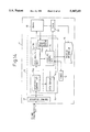
- FIG. 3 is a block diagram showing a first preferred embodiment according to the present invention.
- a first preferred embodiment of an apparatus for controlling high printing in a printer device is illustrated by incorporating a central processing unit (CPU) 13 functioning as a control unit into a printer device 11.
- CPU central processing unit
- the printer device 11 is connected to a certain processor which is not shown. Further, in the printer device 11, a two-way interface 12 is provided which transfers various data to the processor and also receives the data from the processor.
- the CPU 13 is mainly constituted by an input/output control unit 13a, a data analysis unit 13b and a printing control unit 13c.
- the input/output control unit 13a receives printing data represented in the code format or dot format which is sent from the processor via the two-way interface 12, and stores the printing data in a data buffer 14a within a main memory unit 14 which will be hereinafter described.
- the data analysis unit 13b analyzes the printing data stored in the data buffer 14a, and converts the printing data to dot-data represented in the format in which the printing data can be actually printed.
- the printing control unit 13c controls a printer mechanism 18 which is substantially equivalent to the printer 4 shown in FIG. 1 or FIG. 2, and also controls a timer 19 which notifys the CPU 13 of the completion of a process for expanding the dot-data, and the like.
- the main memory unit 14 always includes the above-mentioned input/output control unit 13a, the data analysis unit 13b, the printing control unit 13c, and the like, in a form of processing program s. Further, the main memory unit 14 includes the data buffer 14a indicating a region in which the printing data sent from the processor is stored.
- 15 denotes a bit-map memory (BMM) which corresponds to the BMM 1 shown in FIG. 1 or FIG. 2, and which stores the dot-data represented in the format in which the printing data can be actually printed.
- 16 denotes a drawing LSI (Large Scale Integrated Circuit) which corresponds to the copying unit 3 shown in FIG. 1 or FIG. 2, and which allows the dot-data expanded in a given rectangular region on the BMM 15 to be copied into any other rectangular region on the same BMM 15.
- the drawing LSI 16 operates to transfer the dot-data in the BMM 15 to the printer mechanism 18 which prints the thus transferred dot-data in papers of the designated size.
- FIG. 4 is a block diagram showing in detail a configuration of an input/output control unit in FIG. 3
- FIG. 5 is a block diagram showing in detail a configuration of a data analysis unit in FIG. 3
- FIG. 6 is a block diagram showing in detail a configuration of a printing control unit in FIG. 3.
- any component which is the same as that mentioned before will be referred to using the same reference number.
- the input/output control unit 4 includes a data reception detecting unit 130 and a data storage unit 132.
- the data reception detecting unit 130 checks whether or not printing data which has been sent from the two-way interface 12 is received. If the reception of the printing data is confirmed by the data reception detecting unit 130, the data storage unit 132 temporarily stores the printing data and then transfers the same printing data to the data buffer 14a. At the same time, the data reception detecting unit 130 informs the data analysis unit 13b that the printing data is assuredly received.
- These data reception detecting unit 130 and data storage unit 132 can be preferably realized by processing programs in the CPU 13.
- the data analysis unit 13b includes a data detecting unit 134, a data extracting unit 136, a data/dot-data conversion unit 140, and a page data analysis completion detecting unit 138.
- the page data analysis completion detecting unit 138 checks whether or not a data analysis for one page is finished and that a new page should be used. If it is confirmed that the data analysis for one page is finished, the page data analysis completion detecting unit 138 notifys the printing control unit 13c of the completion of the data analysis for one page.
- These data detecting unit 134, data extracting unit 136, data/dot-data conversion unit 140, and page data analysis completion detecting unit 138 can be preferably realized by processing programs in the CPU 13.
- the printing control unit 13c includes a timer value calculation/decision unit 142, a mechanism reception enable detecting unit 144, a BMM moving control unit 146, and a data transfer monitoring unit 148.
- the timer value calculation/decision unit 142 calculates the time required for transferring the dot-data existing within the area between a position B and a position C to the printer mechanism 18, and determines the timer value of the timer 19. Subsequently, the timer 19 is set to the thus determined timer value corresponding to the transfer time of the dot-data in the area between a position B and a position C.
- the BMM moving control unit 146 activates the drawing LSI 16, and instructs this drawing LSI 16 to copy a portion from a position A through a position C on the BMM 15 into a portion from a position B through a position D on the same BMM 15.
- the mechanism reception enable detecting unit 144 checks whether or not a printing process of the previous page is finished in the printer mechanism 18, and whether or not the dot-data existing within the area between a position B and a position D is ready to be received. When it is confirmed that the the dot-data in the area between a position B and a position D can be received by the printer mechanism 18, the dot-data transfer circuit 17 starts transferring the expanded dot-data to the printer mechanism 18.
- the data transfer monitoring unit 148 checks whether or not a time-out signal, indicating the completion of a process for transferring the dot-data in the area between a position B and a position C to the printer mechanism 18, is generated. If it is confirmed that the time-out signal is generated, printing data of the next page is converted to corresponding dot-data and expanded in the BMM 15, in the case where the unprinted data is left.
- timer value calculation/decision unit 142 can be preferably realized by processing programs in the CPU 13.
- FIG. 7 a front view of the construction of the printer mechanism 18 in FIG. 3 will be illustrated in FIG. 7.
- a printing paper is automatically picked up from a form feeding tray 70, and a heading process of the printing paper is executed. Further, the printing paper passes through an inhalation sensing unit 71 and a photoresist roller 72, and moves upward along a predetermined passage of the printing paper. Alternatively, the printing paper is thrown into a passage of the printing paper from a form feeding guide 73 by a manual operation.
- spare time is usually generated, since the printing paper has to be picked up from the form feeding tray 70 through the inside of the printer mechanism 18.
- the present invention is adapted to shorten the spare time by adjusting the time when the the printing paper is inhaled from the form feeding tray 70.
- FIG. 8 is a diagram for explaining the condition in which a bit-map memory is used in FIG. 1; and FIG. 9 is a diagram for explaining the condition in which a bit-map memory is used in FIG. 2.
- a hatched portion represents an area for printing which is to be printed, i.e., a portion in which dot-data is expanded.
- the size of a printing paper which is used for printing video data is smaller than a half of the whole area used for expanding the printing data of the current page in the BMM 15, as corresponding dot-data.
- the whole memory area indicates a memory area from a position A through a position D, corresponding to the largest (maximum) size of an available paper.
- the size of a printing paper corresponding to the hatched portion i.e., the size of a first area from a position A through a position C on the BMM 15 is smaller than the whole area which can be used for expanding the printing data of the current page, but larger than a half of the whole area.
- the whole memory area also indicates a memory area from a position A through a position D, corresponding to the maximum size of an available paper.
- the size of a printing paper is smaller than a half of the maximum size that can be treated by the printer device, as described before. Therefore, as shown in FIG. 8, the dot-data is expanded in a portion of the BMM 15 that is equal to or smaller than a memory area ranging from a position A through a position B.
- a printing control unit 13c checks whether or not a printing process of the previous page is finished in the printer mechanism 18. As soon as it is confirmed that the above-mentioned process is finished, the printing control unit 13c activates a drawing LSI 16, and instructs this drawing LSI 16 to move the expanded dot-data from a portion between a position A and a position B on the BMM 15 to a portion between a position C and a position D on the same BMM 15. Subsequently, the printing control unit 13c instructs the printer mechanism 18 to start a printing process, and waits for a notice, that the printer mechanism 18 has been ready to receive the dot-data, to be sent from the printer mechanism 18.
- the printing control unit 13c When the printing control unit 13c is notified that the printer mechanism 18 has been ready to receive the dot-data, the printing control unit 13c instructs the dot-data transfer circuit 17 to start transferring the dot-data stored in the BMM 15 to the printer mechanism 18.
- the printing control unit 13c inquires of the data analysis unit 13b whether or not there is the printing data of the next page. When it is confirmed that there is the printing data of the next page, the printing control unit 13c instructs the dot-data transfer circuit 17 and the data analysis unit 13b to carry out in parallel a process for transferring the dot-data between a position C and a position D to the printer mechanism 18 and a process for expanding the printing data of the next page in a portion between a position A and a position B on the BMM 15.
- the data analysis unit 13b can assuredly expand the printing data of the next page to a first area between a position A and a position B, which does not overlap with a second area between a position C and a position D.
- the size of a printing paper is smaller than the maximum size that can be treated by the printer device, but larger than a half of the maximum size, as described before. Therefore, as shown in FIG. 9, the dot-data is expanded in a portion of the BMM 15 that corresponds to a memory area ranging from a position A through a position C.
- a printing control unit 13c checks whether or not a printing process of the previous page is finished in the printer mechanism 18. As soon as it is confirmed that the above-mentioned process is finished, the printing control unit 13c activates a drawing LSI 16, and instructs this drawing LSI 16 to move the expanded dot-data from a portion between a position A and a position C on the BMM 15 to a portion between a position B and a position D on the same BMM 15.
- a data transfer rate in which the expanded dot-data is transferred as video data from the BMM 15 to the printer mechanism 18, is determined by the maximum speed of the printer mechanism 18. Therefore, it becomes possible to calculate in advance the transfer time required for transferring the dot-data existing between a position B and a position C on the BMM 15 .
- the printing control unit 13c can easily calculate the transfer time of the dot-data existing between a position B and a position C on the BMM 15. Subsequently, the printing control unit 13c instructs the printer mechanism 18 to start a printing process, and waits for a notice, that the printer mechanism 18 has been ready to receive the dot-data, to be issued from the printer mechanism 18 .
- the printing control unit 13c sets a timer 19 with the timer value corresponding to the precalculated transfer time required for transferring the dot-data existing between a position B and a position C. Further, the printing control unit 13c instructs the timer 19 to generate a time-out signal, in the case where the predetermined time equivalent to the above-mentioned timer value has elapsed.
- a process for transferring the dot-data stored in the BMM 15 to the printer mechanism 18 is continuously carried out.
- the timer 19 When the transfer of the dot-data existing between a position B and a position C on the BMM 15 is finished, the timer 19 generates the time-out signal to notify the printing control unit 13c of the completion of the transfer of the dot-data between a position B and a position C.
- the printing control unit 13c inquires of the data analysis unit 13b whether or not there is the printing data of the next page. When it is confirmed that there is the printing data of the next page, the printing control unit 13c instructs the data analysis unit 13b to carry out a process for expanding the printing data of the next page. In this case, the printing control unit 13c issues the above-mentioned instruction without waiting for a process for transferring the dot-data between a position C and a position D to be completed.
- the data analysis unit 13b can also expand the printing data of the next page to a first area between a position A and a position C.
- FIG. 10 is a time chart for explaining an operation of a data analysis unit and a printing control unit in the case of FIG. 9. In this case, the sequential operation in the second case will be explained with reference to FIG. 10.
- printing data of the page #1 is expanded in the BMM 15 by means of the data analysis unit 13b.
- the printing control unit 13c activates a drawing LSI 16 and instructs this drawing LSI 16 to move the expanded dot-data from a portion between a position A and a position C on the BMM 15 to a portion between a position B and a position D on the same BMM 15 (time period T2).
- a process for transferring video data from the BMM 15 to the printer mechanism 18 is executed in accordance with an instruction by the printing control unit 13c (time period T3+T1).
- the timer 19 When the transfer of the dot-data between a position B and a position C is finished, the timer 19 generates the time-out signal to notify the printing control unit 13c of the completion of the transfer of the dot-data between a position B and a position C.
- printing data of the page #2 is expanded in the BMM 15 by means of the data analysis unit 13b, in parallel with the transfer of the video data between a position C and a position D (time period T1).
- FIG. 11 is a flowchart for explaining a first part of a procedure for controlling printing in the case of FIG. 9;
- FIGS. 12A and 12B are flowcharts for respectively explaining a second part and a third part of a procedure for controlling printing in the case of FIG. 9;
- FIGS. 13A and 13B are flowcharts for respectively explaining a fourth part and a fifth part of a procedure for controlling printing in the case of FIG. 9.
- the printing control unit 13c activates a drawing LSI 16, and instructs this drawing LSI 16 to copy a portion between a position A and a position C on the BMM 15 to a portion between a position B and a position D on the same BMM 15.
- the printing control unit 13c calculates the time required for emptying a memory area between a position B and a position C on the BMM 15. Further, in a step S9, the printing control unit 13c instructs the printer mechanism 18 to start printing the video data.
- the procedure proceeds to a step S11 of FIG. 13A.
- the printing control unit 13c instructs hardware for dot-data transfer, e.g., the dot-data transfer circuit 17 to start transferring the dot-data which is stored in a portion between a position B and a position D on the BMM 15 to the printer mechanism 18.
- the printing control unit 13c sets a timer 19 with the timer value corresponding to the precalculated transfer time required for transferring the dot-data between a position B and a position C to the printer mechanism 18.
- the data analysis unit 13b determines whether or not the unprinted data, in which a printing process is not yet executed, is left. In the case where the unprinted data is left, the procedure goes back to the step S4 of FIG. 11 and repeats the above-mentioned steps S4 to S13.
- the procedure proceeds to a step S15.
- the printing control unit 13c checks whether or not the transfer of the dot-data between a position C and a position D on the BMM 15 is finished in the printer mechanism 18. When it is notified by the above-mentioned hardware that the transfer of the dot-data between a position C and a position D is finished, every procedure for controlling printing ends.
- the size of a paper which enables the printer mechanism of the printer device to maintain the maximum printing speed is designed to be smaller than the maximum size that can be treated by the printer device.
- the time required for transferring the dot-data between a position C and a position D can be applied to the time required for expanding the dot-data in the BMM 15. Therefore, it becomes possible to reduce the time required for expanding the dot-data and to improve a printing speed (a performance of printing), in comparison with the prior art.
- the maximum printing speed of the printer mechanism When the maximum printing speed of the printer mechanism is to be maintained, it should be noted that the time required for inhaling a printing paper from a form feeding tray through the inside of the printer device is not be negligible. Generally, unless the inhalation of the printing paper of the next page and the transfer of the dot-data to the printer mechanism are executed in parallel, it is difficult for the maximum printing speed of the printer mechanism to be fully utilized.
- a copying control unit 13d is provided in the CPU 13, in place of the drawing LSI of the first preferred embodiment shown in FIG. 3.
- a process for copying the dot-data is designed to be carried out.
- any other component except the copying control unit 13d and the DMA unit 20 is substantially the same as that of the first preferred embodiment. Since the DMA unit 20 is provided in the second preferred embodiment, this second embodiment is more advantageous in treating a large amount of data with high transfer rate.
- a hardware timer is used as the timer in the printer device.
- an operation equivalent to that of the hardware timer can be carried out.
- a two-way interface unit is used as the interface means between a host processor and a printer device.
- the construction of interface means of the present invention is not limited to that of the above-mentioned two-way interface unit.
- a data analysis unit may be constituted by a different independent CPU, so as to reduce the time required for expanding dot-data in the BMM.
- the present invention can be also applied to a printer device having a plurality of CPU.
Abstract
Description
Claims (14)
Applications Claiming Priority (2)
| Application Number | Priority Date | Filing Date | Title |
|---|---|---|---|
| JP5-178657 | 1993-07-20 | ||
| JP17865793A JP3290769B2 (en) | 1993-07-20 | 1993-07-20 | Printer device |
Publications (1)
| Publication Number | Publication Date |
|---|---|
| US5467431A true US5467431A (en) | 1995-11-14 |
Family
ID=16052297
Family Applications (1)
| Application Number | Title | Priority Date | Filing Date |
|---|---|---|---|
| US08/277,566 Expired - Fee Related US5467431A (en) | 1993-07-20 | 1994-07-20 | Method and apparatus for controlling high speed printing |
Country Status (2)
| Country | Link |
|---|---|
| US (1) | US5467431A (en) |
| JP (1) | JP3290769B2 (en) |
Cited By (2)
| Publication number | Priority date | Publication date | Assignee | Title |
|---|---|---|---|---|
| US6353480B1 (en) * | 1991-04-23 | 2002-03-05 | Canon Kabushiki Kaisha | Multi-mode printing control system |
| EP1409261A2 (en) * | 2001-03-09 | 2004-04-21 | Pitney Bowes Inc. | Print signal generation |
Families Citing this family (1)
| Publication number | Priority date | Publication date | Assignee | Title |
|---|---|---|---|---|
| JP4409557B2 (en) | 2006-10-24 | 2010-02-03 | シャープ株式会社 | Image forming apparatus |
Citations (9)
| Publication number | Priority date | Publication date | Assignee | Title |
|---|---|---|---|---|
| JPH02157926A (en) * | 1988-12-09 | 1990-06-18 | Fujitsu Ltd | Printing activating method for printer |
| US5033880A (en) * | 1987-06-01 | 1991-07-23 | Hitachi, Ltd. | Printer with character expansion in accordance with line pitch |
| US5204959A (en) * | 1988-06-30 | 1993-04-20 | Kabushiki Kaisha Toshiba | System for determining image size ratio of data for presentation of proper size on displays or printers from optical storage |
| US5265209A (en) * | 1989-10-30 | 1993-11-23 | Hitachi, Ltd. | Print control apparatus for printing pages having different page sizes using one or more of a plurality of same-sized page buffers |
| US5270831A (en) * | 1990-09-14 | 1993-12-14 | Eastman Kodak Company | Storage and playback of digitized images in digital database together with presentation control file to define image orientation/aspect ratio |
| US5311259A (en) * | 1992-06-19 | 1994-05-10 | Minolta Camera Kabushiki Kaisha | Image forming apparatus |
| US5316396A (en) * | 1991-06-24 | 1994-05-31 | Brother Kogyo Kabushiki Kaisha | Printer capable of printing in a desired print range |
| US5324122A (en) * | 1989-08-28 | 1994-06-28 | Brother Kogyo Kabushiki Kaisha | Page printer capable of changing page size |
| US5361329A (en) * | 1988-08-11 | 1994-11-01 | Canon Kabushiki Kaisha | Data processing apparatus |
-
1993
- 1993-07-20 JP JP17865793A patent/JP3290769B2/en not_active Expired - Fee Related
-
1994
- 1994-07-20 US US08/277,566 patent/US5467431A/en not_active Expired - Fee Related
Patent Citations (9)
| Publication number | Priority date | Publication date | Assignee | Title |
|---|---|---|---|---|
| US5033880A (en) * | 1987-06-01 | 1991-07-23 | Hitachi, Ltd. | Printer with character expansion in accordance with line pitch |
| US5204959A (en) * | 1988-06-30 | 1993-04-20 | Kabushiki Kaisha Toshiba | System for determining image size ratio of data for presentation of proper size on displays or printers from optical storage |
| US5361329A (en) * | 1988-08-11 | 1994-11-01 | Canon Kabushiki Kaisha | Data processing apparatus |
| JPH02157926A (en) * | 1988-12-09 | 1990-06-18 | Fujitsu Ltd | Printing activating method for printer |
| US5324122A (en) * | 1989-08-28 | 1994-06-28 | Brother Kogyo Kabushiki Kaisha | Page printer capable of changing page size |
| US5265209A (en) * | 1989-10-30 | 1993-11-23 | Hitachi, Ltd. | Print control apparatus for printing pages having different page sizes using one or more of a plurality of same-sized page buffers |
| US5270831A (en) * | 1990-09-14 | 1993-12-14 | Eastman Kodak Company | Storage and playback of digitized images in digital database together with presentation control file to define image orientation/aspect ratio |
| US5316396A (en) * | 1991-06-24 | 1994-05-31 | Brother Kogyo Kabushiki Kaisha | Printer capable of printing in a desired print range |
| US5311259A (en) * | 1992-06-19 | 1994-05-10 | Minolta Camera Kabushiki Kaisha | Image forming apparatus |
Cited By (3)
| Publication number | Priority date | Publication date | Assignee | Title |
|---|---|---|---|---|
| US6353480B1 (en) * | 1991-04-23 | 2002-03-05 | Canon Kabushiki Kaisha | Multi-mode printing control system |
| EP1409261A2 (en) * | 2001-03-09 | 2004-04-21 | Pitney Bowes Inc. | Print signal generation |
| EP1409261A4 (en) * | 2001-03-09 | 2007-07-25 | Pitney Bowes Inc | Print signal generation |
Also Published As
| Publication number | Publication date |
|---|---|
| JP3290769B2 (en) | 2002-06-10 |
| JPH0732667A (en) | 1995-02-03 |
Similar Documents
| Publication | Publication Date | Title |
|---|---|---|
| US4992882A (en) | Printer | |
| US7660555B2 (en) | Printing apparatus, information processing apparatus, and control method therefor | |
| JP3344268B2 (en) | Printing control device | |
| US5467431A (en) | Method and apparatus for controlling high speed printing | |
| US4975858A (en) | Controller for a printer for printing data received from an external data processor | |
| JP3438710B2 (en) | Printer and recording medium recording program for controlling the printer | |
| JP3027468B2 (en) | Printing error recovery processing method | |
| JP4085561B2 (en) | Printer | |
| JP3509840B2 (en) | Page printer | |
| JP2002127538A (en) | Printer | |
| US6438334B1 (en) | Image output apparatus and control method therefor | |
| JP4307008B2 (en) | Image forming apparatus | |
| JP2004216778A (en) | Image forming apparatus and method of controlling command therein | |
| JP3083251B2 (en) | Page printer | |
| JP3894259B2 (en) | Printer device | |
| JP2007281773A (en) | Image forming apparatus and control method thereof | |
| JPH10240476A (en) | Printing system, control method for the same and information processor | |
| JP3417426B2 (en) | Image recording device | |
| JPH08118752A (en) | Imaging processing method | |
| JP3316378B2 (en) | Printer device and printing method thereof | |
| JPH1097392A (en) | Print control device and method and storage medium storing readable program for computer | |
| JP2000238386A (en) | Print host, printer and print system comprising them | |
| JPH0930088A (en) | Printer device and control method thereof | |
| JP2002144666A (en) | Print control system, print control method and storage medium | |
| JP2001246811A (en) | Interruption printer |
Legal Events
| Date | Code | Title | Description |
|---|---|---|---|
| AS | Assignment |
Owner name: FUJITSU LIMITED, JAPAN Free format text: ASSIGNMENT OF ASSIGNORS INTEREST;ASSIGNORS:ISHIGURO, HAJIME;MORIOKA, KAZUTOSHI;SAKAI, TOORU;AND OTHERS;REEL/FRAME:007096/0638 Effective date: 19940711 Owner name: PFU LIMITED, JAPAN Free format text: ASSIGNMENT OF ASSIGNORS INTEREST;ASSIGNORS:ISHIGURO, HAJIME;MORIOKA, KAZUTOSHI;SAKAI, TOORU;AND OTHERS;REEL/FRAME:007096/0638 Effective date: 19940711 |
|
| FEPP | Fee payment procedure |
Free format text: PAYOR NUMBER ASSIGNED (ORIGINAL EVENT CODE: ASPN); ENTITY STATUS OF PATENT OWNER: LARGE ENTITY |
|
| FEPP | Fee payment procedure |
Free format text: PAYOR NUMBER ASSIGNED (ORIGINAL EVENT CODE: ASPN); ENTITY STATUS OF PATENT OWNER: LARGE ENTITY Free format text: PAYER NUMBER DE-ASSIGNED (ORIGINAL EVENT CODE: RMPN); ENTITY STATUS OF PATENT OWNER: LARGE ENTITY |
|
| FPAY | Fee payment |
Year of fee payment: 4 |
|
| FPAY | Fee payment |
Year of fee payment: 8 |
|
| REMI | Maintenance fee reminder mailed | ||
| LAPS | Lapse for failure to pay maintenance fees | ||
| STCH | Information on status: patent discontinuation |
Free format text: PATENT EXPIRED DUE TO NONPAYMENT OF MAINTENANCE FEES UNDER 37 CFR 1.362 |
|
| FP | Lapsed due to failure to pay maintenance fee |
Effective date: 20071114 |