US5465408A - AGC circuit for operating in accordance with the nature of the interference signal and method for controlling this circuit - Google Patents
AGC circuit for operating in accordance with the nature of the interference signal and method for controlling this circuit Download PDFInfo
- Publication number
- US5465408A US5465408A US08/067,211 US6721193A US5465408A US 5465408 A US5465408 A US 5465408A US 6721193 A US6721193 A US 6721193A US 5465408 A US5465408 A US 5465408A
- Authority
- US
- United States
- Prior art keywords
- signal
- level
- agc
- attenuation value
- broad
- Prior art date
- Legal status (The legal status is an assumption and is not a legal conclusion. Google has not performed a legal analysis and makes no representation as to the accuracy of the status listed.)
- Expired - Fee Related
Links
- 238000000034 method Methods 0.000 title description 6
- 230000004075 alteration Effects 0.000 claims abstract description 5
- 230000035945 sensitivity Effects 0.000 claims description 34
- 230000003321 amplification Effects 0.000 claims description 11
- 238000003199 nucleic acid amplification method Methods 0.000 claims description 11
- 238000001514 detection method Methods 0.000 claims description 8
- 238000001914 filtration Methods 0.000 claims description 3
- 230000001276 controlling effect Effects 0.000 description 11
- 238000010586 diagram Methods 0.000 description 7
- 230000007423 decrease Effects 0.000 description 5
- 230000005764 inhibitory process Effects 0.000 description 4
- 230000002238 attenuated effect Effects 0.000 description 3
- 230000001105 regulatory effect Effects 0.000 description 2
- 230000005236 sound signal Effects 0.000 description 2
- 239000003990 capacitor Substances 0.000 description 1
- 239000000919 ceramic Substances 0.000 description 1
- 230000008030 elimination Effects 0.000 description 1
- 238000003379 elimination reaction Methods 0.000 description 1
- 230000002401 inhibitory effect Effects 0.000 description 1
- 239000003607 modifier Substances 0.000 description 1
- 230000010355 oscillation Effects 0.000 description 1
- 238000011144 upstream manufacturing Methods 0.000 description 1
Images


Classifications
-
- H—ELECTRICITY
- H03—ELECTRONIC CIRCUITRY
- H03G—CONTROL OF AMPLIFICATION
- H03G3/00—Gain control in amplifiers or frequency changers
- H03G3/20—Automatic control
- H03G3/30—Automatic control in amplifiers having semiconductor devices
- H03G3/3052—Automatic control in amplifiers having semiconductor devices in bandpass amplifiers (H.F. or I.F.) or in frequency-changers used in a (super)heterodyne receiver
-
- H—ELECTRICITY
- H04—ELECTRIC COMMUNICATION TECHNIQUE
- H04B—TRANSMISSION
- H04B1/00—Details of transmission systems, not covered by a single one of groups H04B3/00 - H04B13/00; Details of transmission systems not characterised by the medium used for transmission
- H04B1/06—Receivers
- H04B1/10—Means associated with receiver for limiting or suppressing noise or interference
- H04B1/109—Means associated with receiver for limiting or suppressing noise or interference by improving strong signal performance of the receiver when strong unwanted signals are present at the receiver input
Definitions
- the present invention relates to a characteristic change of an AGC circuit in a radio receiver for receiving a broadcast wave such as FM.
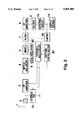
- FIG. 1 is a block diagram illustrating a constitutional example of a conventional FM radio receiver.
- the FM broadcast wave (the RF signal) sent from a broadcasting station is received by an antenna, and the received RF signal is then input to an antenna tuning circuit 2, in which a signal in a predetermined frequency range is selected.
- the output of the antenna tuning circuit 2 is input to an RF amplifier 3 and then amplified therein.
- this RF modifier 3 comprises MOSFET.
- this amplified RF signal is input to an RF tuning circuit 4, in which a signal having a predetermined frequency is selected.
- a tuning frequency in this RF tuning circuit is changable, and so the tuning frequency is changed to select a desired station.
- the output of the RF tuning circuit 4 is input to a mixer 5, and in this mixer 5, it is mixed with a signal of a local oscillation frequency from a local oscillator 6 to become a signal (an IF signal) having an intermediate frequency.
- the signal from the local oscillator 6 depends upon the signal selected in the RF tuning circuit 4, and the frequency of the output from the mixer 5 is always constant (10.7 MHz) irrespective of the frequency of the desired station to be selected.
- the thus obtained IF signal is input to an IF amplifier 8 via a filter 7 which allows the only signal having the highly selective constant frequency (10.7 MHz) to be passed therethrough.
- This filter usually comprises a ceramic filter, and it can remove most signals other than the signal of the desired station.
- the output of this filter is amplified by the IF amplifier 8, and a predetermined frequency is selected by a filter 9 again. Detection is then carried out by a detecting circuit 10 to obtain an audio signal.
- Such a radio receiver has an AGC loop in order to prevent excessively large signals from being input to circuits constituting the radio receiver such as the amplifiers 3, 8 and the mixer 5. That is, the output signal of the mixer 5 is detected by a detecting circuit 11 to monitor an output signal level of the mixer 5. This detection may be carried out for the input signal of the mixer 5. Next, this detecting circuit 11 feeds a signal regarding the detection result to an AGC circuit 12.
- this AGC circuit 12 controls an attenuator 13 by the signal from the detecting circuit 11 to lower the level of the signal to be input to the RF amplifier 3 and simultaneously controls the RF amplifier 3 to lower the output level of the RF amplifier 3.
- This attenuator 13 usually comprises a pin diode, and the value of a signal which flows to an earth side is controlled by the pin diode to lower the level of the input signal of the RF amplifier 3.
- the RF amplifier 3 comprises a dual-gate-MOSFET, and the RF signal is input through a first gate while the control signal from the AGC circuit 12 is input through a second gate to the RF amplifier 3.
- a bias voltage to be applied to the second gate of the FET is lowered to decrease an amplification ratio of the FET.
- the level of the signal to be input to the amplifier and the mixer is lowered in accordance with the level of the received signal, whereby the proper signal level can always be achieved.
- the output of the detecting circuit 10 is input to an output section 14, in which a voice corresponding to the input signal is output through a speaker or the like.
- the level of a radio wave from a station adjacent to the desired station is very high, two-signal interference occurs in the radio receiver having the above-mentioned AGC loop. That is, if a signal having the very high radio wave level is present in the vicinity of the desired station, the signal level of the output from the mixer 5 becomes high, and the RF signal is attenuated by means of the AGC circuit 12. As a result of such an attenuation, the signal of the desired station is also attenuated, so that the level of the obtained audio signal lowers inconveniently.
- radio receiver interference also includes inter modulation (IM).
- IM inter modulation
- radio receiver interference when there are two frequencies (f1, f2), a signal having a frequency of 2f2-f1 is produced. If the two frequencies f1, f2 are present at relatively near frequencies, a signal generated by the inter modulation has about the same frequency as in another broadcasting station in a certain case, so that inter modulation interference (IM interference) occurs.
- the signal generated by such an IM interference is output as the signal having the frequency of the desired station, and so it appears as the output of the detecting circuit 10. Therefore, if there is a control system for lowering the AGC sensitivity in the case that the output of the detecting circuit 10 is small as described above, the signal generated by such an IM interference is amplified and output.
- the IM interference can be prevented by attenuating the RF signal, and therefore, owing to the operation retard of the AGC circuit as described above, the radio receiver more easily undergoes this IM interference.
- the AGC sensitivity is regulated on the balance of the inhibition of this two-signal interference and the inhibition of the IM interference, but it is difficult to sufficiently inhibit both types of interference.
- An object of the present invention is to provide an AGC circuit of a radio receiver capable of suitably inhibiting interference in accordance with the kind of interference and a method for controlling the AGC circuit.
- a radio receiver regarding the present invention has an AGC circuit for operating in accordance with the kind of interference signal, and the AGC circuit comprises
- a mixing circuit for mixing an RF signal with a signal having a predetermined frequency to obtain intermediate frequency signals
- a filter means for extracting a signal of a certain frequency from these intermediate frequency signals to obtain the signal of a desired station
- a desired station signal level detecting means for detecting the level of the signal of the desired station which is the output of this filter means
- an attenuating means for attenuating the RF signal to be input to the mixing circuit
- a broad-band signal level detecting means for detecting the level of a broad-band signal prior to filtering by the filter means
- an attenuation value controlling means for controlling an attenuation value in the attenuating means on the basis of detected results of the desired station signal level detecting means and the broad-band signal level detecting means.
- the attenuation value controlling means detects a change state of the level of the desired station signal at a time when an attenuation degree is changed by the attenuating means, and it also controls the attenuation value in the attenuating means in accordance with this change state.
- the two-signal interference and the inter modulation interference can be distinguished from each other. That is, in the case of the inter modulation interference, a ratio of the change of the desired signal level to that of the attenuation degree is higher than in the case of the two-signal interference. Therefore, it is possible to Judge the presence of the interference and the kind of interference, and therefore the control can be given in accordance with the nature of the interference. As a result, a suitable signal can be achieved by the proper inhibition of the interference.
- the above-mentioned attenuation value controlling means increases the attenuation value, when the level change of the desired station signal is large at the time of the alteration of the attenuation degree.
- This constitution permits the effective inhibition of the inter modulation interference.
- the above-mentioned attenuation value controlling means contains an amplifier for the signal to be input to the broad-band signal level detecting means, and it changes an amplification degree in this amplifier to alter the level of the broad-band signal to be input to the attenuation value controlling means, thereby the attenuation value in the attenuating means is changed.
- a plurality of the amplifiers are disposed, and any one of these amplifiers is selected to change the amplification degree.
- the present invention is directed to a method for controlling the operation of an AGC circuit in a radio receiver which comprises
- a mixing circuit for mixing an RF signal with a signal having a predetermined frequency to obtain intermediate frequency signals
- a filter means for extracting a signal of a certain frequency from these intermediate frequency signals to obtain the signal of a desired station
- a desired station signal level detecting means for detecting the level of the signal of the desired station which is the output of this filter means
- an attenuating means for attenuating the RF signal to be input to the mixing circuit
- a broad-band signal level detecting means for detecting the level of a broad-band signal prior to filtering by the filter means
- This constitution permits the control of the attenuation value in accordance with the kind of interference.
- Another embodiment of the present invention further contains a step of judging whether or not the level of the desired signal is high in the case that the change ratio detected in the detecting step is 1:1, and when the level of the desired signal is high, the attenuation value is lowered to a relatively low value.
- FIG. 1 is a block diagram illustrating the constitution of a conventional radio receiver.
- FIG. 2 is a block diagram illustrating the constitution of an embodiment.
- FIG. 4 is a flow chart illustrating the setting procedure of AGC sensitivity.
- FIG. 5 is a characteristic diagram illustrating a relationship between an attenuation value for the judgment of IM interference and an output from an S-meter.
- FIG. 2 is a block diagram illustrating the overall constitution of the embodiment, and the same symbols as in FIG. 1 will be attached to the same members and the description of the same members will be omitted.
- This embodiment has an S-meter (signal meter) 50, a variable AGC circuit 60 and a switching control section 62.
- the S-meter 50 detects the level of the output of a detecting circuit, i.e., the level of a desired signal.
- This kind of S-meter is what is employed in a conventional device.
- variable AGC circuit 60 controls attenuation on-off in an attenuator 13 and the drop in an amplification ratio, i.e., attenuation in an RF amplifier 3 in accordance with the level of a broad-band signal before passing through a filter 7 which is an output from a mixer 5. Furthermore, the variable AGC circuit 60 is constituted so as to change its sensitivity in accordance with a signal from the switching control section 62. Here, “changing the sensitivity" is substantially equal to "controlling an attenuation value in accordance with the level of the broad-band signal".
- the attenuator 13 when the sensitivity is heightened, the attenuator 13 is begun even at a relatively low level of an output from the mixer 5, and the start of the attenuation due to the decrease in amplification ratio in the RF amplifier 3 is hastened and the attenuation value increases.
- control signal regarding the attenuation value in the RF amplifier 3 which is the output of the variable AGC circuit 60 and the detecting signal of the S-meter 50.
- the control signal regarding the attenuation value in the RF amplifier 3 corresponds to the broad-band signal, and as shown by a dotted line in FIG. 2, the output signal from the mixer 5 may be directly input to the switching control section 62.
- the switching control section 62 To the switching control section 62, the desired station signal which is the output of the S-meter 50 and the broad-band signal on the upstream of the filter 7 are input.
- the switching control section 62 judges the presence of the interference and its kind in accordance with the levels of the two signals. On the basis of this judgment, the switching control section 62 controls the variable AGC circuit 60, whereby the attenuation values in the RF amplifier 3 and the attenuator 13 are regulated.
- an input or output signal of the mixing circuit 5 is input to a switch 42 via a capacitor 40.
- This switch 42 is a change-over switch for switching a route for outputting the input signal, and in this embodiment, the signal to be input is fed to any of three level detectors 44a, 44b and 44c.
- level detectors 44a, 44b and 44c are each provided with amplifiers having different amplification ratios, and they output a signal regarding a level detection result of the amplified signal.
- the output sides of these level detectors 44a, 44b and 44c are connected to an AGC circuit 46, and this AGC circuit 46 operates in accordance with the signal fed from any of the level detectors 44.
- the AGC circuit 46 feeds a predetermined current to the attenuator 13 via an antenna dumping circuit 48 to release a part of the signal on the input side of the RF amplifier 3 through an earth, whereby the signal to be input to the RF amplifier 3 is reduced. Furthermore, in the case that the level of the input signal is higher than a second level, the AGC circuit 46 decreases the voltage to be input to the second gate 3b of the RF amplifier 3 and decreases the amplification ratio of the RF amplifier 3.
- one detector is selected from the three level detectors 44a to 44c by the switch 42.
- the sensitivity of AGC is changed by the switch 42. That is, when the amplification ratios of the level detector 44a, 44b and 44c are set to a low degree, a middle degree and a high degree, respectively, and when the level detector 44a is selected, the AGC sensitivity is lowest, and when the level detector 44c is selected, the AGC sensitivity is highest.
- the level of a signal of the desired station after the wave detection is detected by the S-meter 50.
- the output of this S-meter 50 is fed to a controller 54 for AGC via an AD converter 52.
- the output signal of the AGC circuit 46 is fed to the AGC controller 54 via an AD converter 56.
- This controller 54 for AGC controls the switch 42.
- the controller 54 for AGC forwards a signal to the switch 42 as initialization, and selects, for example, the level detector 44b, whereby the AGC sensitivity is set to the middle degree.
- the controller 54 for AGC receives signals from the AD converters 52, 56 to recognize the information of the desired station level and the broad-band signal level.
- the controller 54 judges from the two signals whether or not interference occurs and the kind of interference, if any.
- the controller 54 carries out the sensitivity switch of AGC, i.e., the selection of the level detector 44 on the basis of the above-mentioned judgment.
- the controller 54 for AGC sends the signal to the switch 42 to change the AGC sensitivity. That is, since the level detector 44b has been employed as the initialization, the level detector 44a or 44c is selected, whereby an attenuation value is changed in a predetermined range by the AGC circuit 46.
- a variate of the output from the S-meter 50 is inspected.
- the received signal is a signal of a desired station
- the output signal level of the S-meter 50 alters in a ratio of 1:1 as shown by a solid line in FIG. 5.
- the level detector 44c is selected by the switch 42, so that the AGC sensitivity is set to the high degree (S5), whereby the large attenuation value is set by the AGC circuit 46. Since the signal attributed to the inter modulation is attenuated three times as much as the attenuation value, it is possible to suppress the level of the input signal to the mixer 5 and prevent the IM interference from taking place.
- the output of the S-meter 50 is low in S1
- the broad-band signal level is also low, the level of the signal itself of the desired station is judged to be low, and it is Judged that the normal receive will be achieved.
- the operation transfers to S4, in which the AGC sensitivity is set to the middle degree.
- the AGC sensitivity is changed by the same procedure as in S2 and S3 to alter the attenuation value of the RF signal, thereby changing the output of the S-meter 50 (S7, S8). If a ratio of the change of the attenuation value to that of the output of the S-meter 50 is not 1:1, it is judged that the IM interference takes place, so that the operation transfers to S5 to set the AGC sensitivity to the high degree.
- the level detector 44c is selected by the switch 42, so that the AGC sensitivity is set to the high degree, whereby the signal of the desired station can be protected from excessive attenuation.
- the three level detectors 44 are disposed, and for the sake of the sensitivity change for the IM interference detection in S2 and S7 and the final sensitivity setting in S4, S5 and S9, one sensitivity is utilized.
- the five level detectors 44 are disposed and the sensitivities of these detectors are differently set.
- the six or more level detectors 44 may be disposed, and the AGC sensitivities may be set so as to be suitably switched.
- the kind of interference can be judged, and the AGC sensitivity can be switched in accordance with the IM interference or the 2-signal interference, whereby a suitable receive of an FM radio wave can be achieved.
Landscapes
- Engineering & Computer Science (AREA)
- Computer Networks & Wireless Communication (AREA)
- Signal Processing (AREA)
- Circuits Of Receivers In General (AREA)
- Control Of Amplification And Gain Control (AREA)
Abstract
Description
Claims (6)
Applications Claiming Priority (2)
| Application Number | Priority Date | Filing Date | Title |
|---|---|---|---|
| JP4137375A JPH05335855A (en) | 1992-05-29 | 1992-05-29 | Radio receiver |
| JP4-137375 | 1992-05-29 |
Publications (1)
| Publication Number | Publication Date |
|---|---|
| US5465408A true US5465408A (en) | 1995-11-07 |
Family
ID=15197219
Family Applications (1)
| Application Number | Title | Priority Date | Filing Date |
|---|---|---|---|
| US08/067,211 Expired - Fee Related US5465408A (en) | 1992-05-29 | 1993-05-26 | AGC circuit for operating in accordance with the nature of the interference signal and method for controlling this circuit |
Country Status (2)
| Country | Link |
|---|---|
| US (1) | US5465408A (en) |
| JP (1) | JPH05335855A (en) |
Cited By (28)
| Publication number | Priority date | Publication date | Assignee | Title |
|---|---|---|---|---|
| US5638141A (en) * | 1994-04-29 | 1997-06-10 | Samsung Electronics Co., Ltd. | Broadcast signal receiver having a low-noise amplifier inserted before a tuner |
| US5697081A (en) * | 1995-09-12 | 1997-12-09 | Oki Telecom, Inc. | Intermodulation distortion reduction circuit utilizing variable attenuation |
| US5722061A (en) * | 1994-12-16 | 1998-02-24 | Qualcomm Incorporated | Method and apparatus for increasing receiver immunity to interference |
| EP0847193A1 (en) * | 1996-12-06 | 1998-06-10 | Koninklijke Philips Electronics N.V. | Intermediate frequency amplifier circuit for radiowave receiver |
| FR2756988A1 (en) * | 1996-12-06 | 1998-06-12 | Philips Electronics Nv | Integrated IF amplifier circuit for TV reception |
| KR19990055485A (en) * | 1997-12-27 | 1999-07-15 | 구자홍 | Digital signal level measuring device |
| US5990746A (en) * | 1996-09-12 | 1999-11-23 | Nokia Mobile Phones Limited | Amplifier system |
| US6037999A (en) * | 1997-03-27 | 2000-03-14 | Alps Electric Co., Ltd. | Tuner for receiving television signal |
| US6078798A (en) * | 1997-03-31 | 2000-06-20 | Sanyo Electric Co., Ltd. | Radio receiver with object station sensitivity |
| US6212244B1 (en) * | 1998-01-09 | 2001-04-03 | Golden Bridge Technology, Inc. | Fast response automatic gain control |
| US6236842B1 (en) * | 1997-03-28 | 2001-05-22 | Sanyo Electric Co., Ltd. | Radio receiver |
| US6236863B1 (en) | 1997-03-31 | 2001-05-22 | Oki Telecom, Inc. | Comprehensive transmitter power control system for radio telephones |
| US6311048B1 (en) * | 1998-09-24 | 2001-10-30 | Aravind Loke | Intelligent control of receiver linearity based on interference |
| US6529718B1 (en) * | 1998-07-24 | 2003-03-04 | Pioneer Electric Corporation | Receiver with a search circuit |
| US6553214B1 (en) | 1999-05-05 | 2003-04-22 | Tenatronics Limited | Active window glass antenna system with automatic overload protection circuit |
| US20030153291A1 (en) * | 2002-02-08 | 2003-08-14 | Pioneer Corporation | AGC circuit of receiver using several local oscillation frequencies |
| US6611680B2 (en) * | 1997-02-05 | 2003-08-26 | Telefonaktiebolaget Lm Ericsson (Publ) | Radio architecture |
| US20040153879A1 (en) * | 2002-01-22 | 2004-08-05 | Junichi Fukutani | High-frequency signal reception apparatus and manufacturing method thereof |
| US20040198286A1 (en) * | 2002-04-25 | 2004-10-07 | Shahla Khorram | Signal gain adjustment within an RF integrated circuit |
| EP1691489A1 (en) * | 2003-11-26 | 2006-08-16 | Niigata Seimitsu Co., Ltd. | Automatic gain control device |
| KR100615535B1 (en) | 2004-07-26 | 2006-08-25 | 삼성전자주식회사 | RF receiver using AGC and methods thereof |
| US20070155351A1 (en) * | 2006-04-07 | 2007-07-05 | Matsushita Electric Industrial Co., Ltd. | Receiving apparatus |
| US20070274377A1 (en) * | 2004-01-30 | 2007-11-29 | Choong-Il Yeh | Apparatus and Method for Measuring Received Signal Strength Indicator, and Recording Medium Storing Program Embodying the Same Method |
| US20090201426A1 (en) * | 2008-02-11 | 2009-08-13 | Hiromichi Sano | Dynamic RF AGC switch/mixer for optimal NTSC video detection |
| US20100066427A1 (en) * | 2008-09-17 | 2010-03-18 | Lockheed Martin Corporation | Stepped delay control of integrated switches |
| WO2013091171A1 (en) * | 2011-12-20 | 2013-06-27 | 中兴通讯股份有限公司 | Method and system for realizing auto gain control |
| CN101959288B (en) * | 2009-07-15 | 2013-08-21 | 展讯通信(上海)有限公司 | Automatic gain control regulating method for received signals and signal receiving equipment |
| US10045626B1 (en) | 2014-08-25 | 2018-08-14 | Stephen H Cheetham | Portable elbow rest and method of use |
Families Citing this family (6)
| Publication number | Priority date | Publication date | Assignee | Title |
|---|---|---|---|---|
| US5722063A (en) * | 1994-12-16 | 1998-02-24 | Qualcomm Incorporated | Method and apparatus for increasing receiver immunity to interference |
| JP2004096404A (en) * | 2002-08-30 | 2004-03-25 | Toyota Industries Corp | Receiver and automatic gain control method thereof |
| JP4519451B2 (en) * | 2003-11-27 | 2010-08-04 | アルパイン株式会社 | Receiver and gain adjustment method |
| JP2007129576A (en) * | 2005-11-04 | 2007-05-24 | Mitsubishi Electric Corp | Mobile reception terminal |
| JP2009027329A (en) * | 2007-07-18 | 2009-02-05 | Niigata Seimitsu Kk | Automatic gain control circuit |
| WO2017208303A1 (en) | 2016-05-30 | 2017-12-07 | 三菱電機株式会社 | Radio interference station elimination device, receiver, and radio interference station elimination method |
Citations (3)
| Publication number | Priority date | Publication date | Assignee | Title |
|---|---|---|---|---|
| US4455681A (en) * | 1981-12-21 | 1984-06-19 | Wile Donald T | Dual threshold wide band/narrow band AGC |
| US4955073A (en) * | 1987-11-19 | 1990-09-04 | Sanyo Electric Co., Ltd. | Automatic search tuner |
| US4955077A (en) * | 1987-11-16 | 1990-09-04 | Sanyo Electric Co., Ltd. | Radio with broad band automatic gain control circuit |
-
1992
- 1992-05-29 JP JP4137375A patent/JPH05335855A/en active Pending
-
1993
- 1993-05-26 US US08/067,211 patent/US5465408A/en not_active Expired - Fee Related
Patent Citations (3)
| Publication number | Priority date | Publication date | Assignee | Title |
|---|---|---|---|---|
| US4455681A (en) * | 1981-12-21 | 1984-06-19 | Wile Donald T | Dual threshold wide band/narrow band AGC |
| US4955077A (en) * | 1987-11-16 | 1990-09-04 | Sanyo Electric Co., Ltd. | Radio with broad band automatic gain control circuit |
| US4955073A (en) * | 1987-11-19 | 1990-09-04 | Sanyo Electric Co., Ltd. | Automatic search tuner |
Cited By (42)
| Publication number | Priority date | Publication date | Assignee | Title |
|---|---|---|---|---|
| US5638141A (en) * | 1994-04-29 | 1997-06-10 | Samsung Electronics Co., Ltd. | Broadcast signal receiver having a low-noise amplifier inserted before a tuner |
| US5722061A (en) * | 1994-12-16 | 1998-02-24 | Qualcomm Incorporated | Method and apparatus for increasing receiver immunity to interference |
| US6026285A (en) * | 1995-09-12 | 2000-02-15 | Oki Telecom, Inc. | Intermodulation distortion reduction circuit utilizing variable attenuation |
| US5697081A (en) * | 1995-09-12 | 1997-12-09 | Oki Telecom, Inc. | Intermodulation distortion reduction circuit utilizing variable attenuation |
| US6104919A (en) * | 1995-09-12 | 2000-08-15 | Oki Telecom, Inc. | Intermodulation distortion reduction circuit utilizing variable attenuation |
| US5990746A (en) * | 1996-09-12 | 1999-11-23 | Nokia Mobile Phones Limited | Amplifier system |
| FR2756988A1 (en) * | 1996-12-06 | 1998-06-12 | Philips Electronics Nv | Integrated IF amplifier circuit for TV reception |
| EP0847193A1 (en) * | 1996-12-06 | 1998-06-10 | Koninklijke Philips Electronics N.V. | Intermediate frequency amplifier circuit for radiowave receiver |
| US6973290B2 (en) | 1997-02-05 | 2005-12-06 | Telefonaktiebolaget L M Ericsson (Publ) | Radio architecture |
| US6611680B2 (en) * | 1997-02-05 | 2003-08-26 | Telefonaktiebolaget Lm Ericsson (Publ) | Radio architecture |
| DE19813510C2 (en) * | 1997-03-27 | 2003-07-31 | Alps Electric Co Ltd | Tuner for television signal reception |
| US6037999A (en) * | 1997-03-27 | 2000-03-14 | Alps Electric Co., Ltd. | Tuner for receiving television signal |
| US6236842B1 (en) * | 1997-03-28 | 2001-05-22 | Sanyo Electric Co., Ltd. | Radio receiver |
| KR100427736B1 (en) * | 1997-03-31 | 2004-06-16 | 산요덴키가부시키가이샤 | Radio receiver |
| US6078798A (en) * | 1997-03-31 | 2000-06-20 | Sanyo Electric Co., Ltd. | Radio receiver with object station sensitivity |
| US6236863B1 (en) | 1997-03-31 | 2001-05-22 | Oki Telecom, Inc. | Comprehensive transmitter power control system for radio telephones |
| KR19990055485A (en) * | 1997-12-27 | 1999-07-15 | 구자홍 | Digital signal level measuring device |
| US6212244B1 (en) * | 1998-01-09 | 2001-04-03 | Golden Bridge Technology, Inc. | Fast response automatic gain control |
| US6529718B1 (en) * | 1998-07-24 | 2003-03-04 | Pioneer Electric Corporation | Receiver with a search circuit |
| US6311048B1 (en) * | 1998-09-24 | 2001-10-30 | Aravind Loke | Intelligent control of receiver linearity based on interference |
| US6553214B1 (en) | 1999-05-05 | 2003-04-22 | Tenatronics Limited | Active window glass antenna system with automatic overload protection circuit |
| US20040153879A1 (en) * | 2002-01-22 | 2004-08-05 | Junichi Fukutani | High-frequency signal reception apparatus and manufacturing method thereof |
| US7630686B2 (en) * | 2002-01-22 | 2009-12-08 | Panasonic Corporation | Radio-frequency-signal receiver and method of manufacturing the same |
| US20030153291A1 (en) * | 2002-02-08 | 2003-08-14 | Pioneer Corporation | AGC circuit of receiver using several local oscillation frequencies |
| US7035610B2 (en) * | 2002-02-08 | 2006-04-25 | Pioneer Corporation | AGC circuit of receiver using several local oscillation frequencies |
| US20040198286A1 (en) * | 2002-04-25 | 2004-10-07 | Shahla Khorram | Signal gain adjustment within an RF integrated circuit |
| US6859646B2 (en) * | 2002-04-25 | 2005-02-22 | Broadcom Corp | Signal gain adjustment within an RF integrated circuit |
| US20060217094A1 (en) * | 2003-11-26 | 2006-09-28 | Niigata Seimitsu Co., Ltd. | Automatic gain control device |
| EP1691489A1 (en) * | 2003-11-26 | 2006-08-16 | Niigata Seimitsu Co., Ltd. | Automatic gain control device |
| US7561863B2 (en) | 2003-11-26 | 2009-07-14 | Niigata Seimitsu Co., Ltd. | Automatic gain control device |
| EP1691489A4 (en) * | 2003-11-26 | 2008-07-02 | Niigata Seimitsu Co Ltd | Automatic gain control device |
| US20070274377A1 (en) * | 2004-01-30 | 2007-11-29 | Choong-Il Yeh | Apparatus and Method for Measuring Received Signal Strength Indicator, and Recording Medium Storing Program Embodying the Same Method |
| US7738544B2 (en) | 2004-01-30 | 2010-06-15 | Electronics & Telecommunications Research Institute | Apparatus and method for measuring received signal strength indicator, and recording medium storing program embodying the same method |
| KR100615535B1 (en) | 2004-07-26 | 2006-08-25 | 삼성전자주식회사 | RF receiver using AGC and methods thereof |
| US20070155351A1 (en) * | 2006-04-07 | 2007-07-05 | Matsushita Electric Industrial Co., Ltd. | Receiving apparatus |
| US20090201426A1 (en) * | 2008-02-11 | 2009-08-13 | Hiromichi Sano | Dynamic RF AGC switch/mixer for optimal NTSC video detection |
| US8456579B2 (en) | 2008-02-11 | 2013-06-04 | Sony Corporation | Dynamic RF AGC switch/mixer for optimal NTSC video detection |
| US20100066427A1 (en) * | 2008-09-17 | 2010-03-18 | Lockheed Martin Corporation | Stepped delay control of integrated switches |
| US8710899B2 (en) | 2008-09-17 | 2014-04-29 | Lockheed Martin Corporation | Stepped delay control of integrated switches |
| CN101959288B (en) * | 2009-07-15 | 2013-08-21 | 展讯通信(上海)有限公司 | Automatic gain control regulating method for received signals and signal receiving equipment |
| WO2013091171A1 (en) * | 2011-12-20 | 2013-06-27 | 中兴通讯股份有限公司 | Method and system for realizing auto gain control |
| US10045626B1 (en) | 2014-08-25 | 2018-08-14 | Stephen H Cheetham | Portable elbow rest and method of use |
Also Published As
| Publication number | Publication date |
|---|---|
| JPH05335855A (en) | 1993-12-17 |
Similar Documents
| Publication | Publication Date | Title |
|---|---|---|
| US5465408A (en) | AGC circuit for operating in accordance with the nature of the interference signal and method for controlling this circuit | |
| US5390345A (en) | Method for preventing desensitization and radio interference of radio receivers | |
| US7580690B2 (en) | High-frequency receiver having a gain switch controller | |
| US4955077A (en) | Radio with broad band automatic gain control circuit | |
| US6389272B1 (en) | Receiver with auto gain control circuit of RF signal | |
| US5722060A (en) | Radio receiver | |
| US5507022A (en) | Electric field level detecting apparatus | |
| US4598426A (en) | Variable intermediate bandwidth AM receiver | |
| US5537675A (en) | Splatter controlling noise blanker | |
| KR100414371B1 (en) | Apparatus and method for controlling operation range of receiver by using automatic gain control voltage | |
| JP2797845B2 (en) | AM tuner | |
| US4580286A (en) | Noise activated mute for FM reception in an AM/FM radio receiver | |
| JP3626350B2 (en) | Receiver | |
| JPH06291688A (en) | Receiver | |
| JP3291462B2 (en) | Radio receiver | |
| JPH057784Y2 (en) | ||
| JP3070987B2 (en) | Automatic tuning circuit | |
| JP2962380B2 (en) | Receiver | |
| JPH0779171A (en) | Receiver | |
| EP0132307A2 (en) | Receiver having a noise blanker | |
| JPH06132838A (en) | Out-band interference wave removing device | |
| JP3070988B2 (en) | Automatic tuning circuit | |
| JP2002064393A (en) | Receiving power control method and receiver | |
| JPH033425A (en) | Radio transmitter/receiver | |
| JPH0317254B2 (en) |
Legal Events
| Date | Code | Title | Description |
|---|---|---|---|
| AS | Assignment |
Owner name: SANYO ELECTRIC CO., LTD., JAPAN Free format text: ASSIGNMENT OF ASSIGNORS INTEREST;ASSIGNORS:SUGAYAMA, SAKAE;ASAMI, TAKAO;KATO, KENJI;AND OTHERS;REEL/FRAME:006609/0539 Effective date: 19930519 Owner name: NISSAN MOTOR CO., LTD., JAPAN Free format text: ASSIGNMENT OF ASSIGNORS INTEREST;ASSIGNORS:SUGAYAMA, SAKAE;ASAMI, TAKAO;KATO, KENJI;AND OTHERS;REEL/FRAME:006609/0539 Effective date: 19930519 Owner name: CLARION CO., LTD., JAPAN Free format text: ASSIGNMENT OF ASSIGNORS INTEREST;ASSIGNORS:SUGAYAMA, SAKAE;ASAMI, TAKAO;KATO, KENJI;AND OTHERS;REEL/FRAME:006609/0539 Effective date: 19930519 Owner name: TOTTORI SANYO ELECTRIC CO., LTD., JAPAN Free format text: ASSIGNMENT OF ASSIGNORS INTEREST;ASSIGNORS:SUGAYAMA, SAKAE;ASAMI, TAKAO;KATO, KENJI;AND OTHERS;REEL/FRAME:006609/0539 Effective date: 19930519 |
|
| FEPP | Fee payment procedure |
Free format text: PAYOR NUMBER ASSIGNED (ORIGINAL EVENT CODE: ASPN); ENTITY STATUS OF PATENT OWNER: LARGE ENTITY |
|
| FPAY | Fee payment |
Year of fee payment: 4 |
|
| FPAY | Fee payment |
Year of fee payment: 8 |
|
| REMI | Maintenance fee reminder mailed | ||
| LAPS | Lapse for failure to pay maintenance fees | ||
| STCH | Information on status: patent discontinuation |
Free format text: PATENT EXPIRED DUE TO NONPAYMENT OF MAINTENANCE FEES UNDER 37 CFR 1.362 |
|
| FP | Lapsed due to failure to pay maintenance fee |
Effective date: 20071107 |