US5456346A - Continuous conveyor for transporting individual hangers - Google Patents
Continuous conveyor for transporting individual hangers Download PDFInfo
- Publication number
- US5456346A US5456346A US08/255,164 US25516494A US5456346A US 5456346 A US5456346 A US 5456346A US 25516494 A US25516494 A US 25516494A US 5456346 A US5456346 A US 5456346A
- Authority
- US
- United States
- Prior art keywords
- chain
- frame
- conveyor
- conveyor according
- transport
- Prior art date
- Legal status (The legal status is an assumption and is not a legal conclusion. Google has not performed a legal analysis and makes no representation as to the accuracy of the status listed.)
- Expired - Fee Related
Links
- 230000001681 protective effect Effects 0.000 claims description 15
- 230000001154 acute effect Effects 0.000 claims description 6
- 230000006835 compression Effects 0.000 claims description 6
- 238000007906 compression Methods 0.000 claims description 6
- 208000027418 Wounds and injury Diseases 0.000 description 1
- 238000011109 contamination Methods 0.000 description 1
- 230000006378 damage Effects 0.000 description 1
- 208000014674 injury Diseases 0.000 description 1
- 239000000314 lubricant Substances 0.000 description 1
- 238000012423 maintenance Methods 0.000 description 1
- 239000002184 metal Substances 0.000 description 1
- 238000012986 modification Methods 0.000 description 1
- 230000004048 modification Effects 0.000 description 1
- 238000004806 packaging method and process Methods 0.000 description 1
- 239000010409 thin film Substances 0.000 description 1
Images
Classifications
-
- B—PERFORMING OPERATIONS; TRANSPORTING
- B65—CONVEYING; PACKING; STORING; HANDLING THIN OR FILAMENTARY MATERIAL
- B65G—TRANSPORT OR STORAGE DEVICES, e.g. CONVEYORS FOR LOADING OR TIPPING, SHOP CONVEYOR SYSTEMS OR PNEUMATIC TUBE CONVEYORS
- B65G19/00—Conveyors comprising an impeller or a series of impellers carried by an endless traction element and arranged to move articles or materials over a supporting surface or underlying material, e.g. endless scraper conveyors
- B65G19/02—Conveyors comprising an impeller or a series of impellers carried by an endless traction element and arranged to move articles or materials over a supporting surface or underlying material, e.g. endless scraper conveyors for articles, e.g. for containers
- B65G19/025—Conveyors comprising an impeller or a series of impellers carried by an endless traction element and arranged to move articles or materials over a supporting surface or underlying material, e.g. endless scraper conveyors for articles, e.g. for containers for suspended articles
-
- B—PERFORMING OPERATIONS; TRANSPORTING
- B65—CONVEYING; PACKING; STORING; HANDLING THIN OR FILAMENTARY MATERIAL
- B65G—TRANSPORT OR STORAGE DEVICES, e.g. CONVEYORS FOR LOADING OR TIPPING, SHOP CONVEYOR SYSTEMS OR PNEUMATIC TUBE CONVEYORS
- B65G2201/00—Indexing codes relating to handling devices, e.g. conveyors, characterised by the type of product or load being conveyed or handled
- B65G2201/02—Articles
- B65G2201/0229—Clothes, clothes hangers
Definitions
- the invention relates to a conveyor, and more particularly to a continuous conveyor with a driven chain for transporting individual hangers by their hooks.
- the hanger hooks can be suspended from a rotatably mounted feed screw, and a transport movement in the horizontal direction can be conferred on them by the rotation of the feed screw (DE-OS 25 06 587).
- Automatic loading of the hanger hooks onto such a spindle conveyor is not reproducible because it is not possible to predict which turn of the feed screw will engage and transport the hanger hooks.
- German Patent 22 63 330 teaches providing a vertically circulating chain with lateral pushers to transport articles of clothing hanging on hangers in the vertical direction, the hooks of the clothes hangers being suspended on the pushers. In this fashion, for example, transportation over several stories of a building is possible.
- German Patent 38 07 280 and U.S. Pat. No. 4,903,819 disclose an unloading device for support hanger conveyor carriages in which the hanger hooks are pushed individually along a sliding rod by a circulating conveyor provided with pushers, located above the hanger hooks. The pusher on the conveyor engages the hanger hooks from above. The hanger hook is guided by the sliding rod supporting it.
- DE-GM 70 11 838 discloses a roller chain with collateral transporting clamps (5).
- the transporting clamps bear upwardly projected transporting jaws (7), which are pivotally mounted.
- This type of transporting chain is used with packaging machines, for example for transporting small boxes.
- the pivotability of the jaws (7) enables the chain to be adjusted to transport boxes of different sizes. In this arrangement, the jaws will not be pivotable unless the chain is horizontal.
- DE-GM 92 10 120 which was registered in Germany as a GM on Dec. 12, 1993, after the priority date of the present application.
- An important goal of the invention is to provide a conveyor, especially a continuous conveyor, for individual hangers, which is simple in design, ensures a space-saving arrangement, and ensures safe guidance of the clothes hangers and/or clothes hanger hooks.
- a continuous conveyor for transporting articles of clothing hanging on hangers provided with hooks, comprising a circulating driven chain; a frame which guides the chain inclined by an acute angle with respect to a horizontal; individual chain links of the chain having pushers projecting from the chain for engaging and pushing the hangers.
- the tilted position of the chain of the conveyor causes the latter to travel parallel to the angled portion of a clothes hanger hook, so that contact of the conveyor with the clothing hanging on the hanger can be reliably avoided even when the hanger hook is made very short.
- the pushers may have a predetermined spacing which defines the tolerances of the conveyor, making the latter especially suitable as a transfer conveyor from one conveyor circuit to another.
- each pusher may be substantially perpendicular to the transport direction.
- the pushers may be substantially triangular.
- the pushers may further be mounted offset from a lengthwise axis of the chain.
- the eccentric arrangement of the pushers on the chain causes the hangers to arrange themselves transversely during transport, at a desirable angle to the transport direction, resulting in considerably improved guidance.
- the chain is advantageously guided in a frame divided crosswise by a dividing gap, to define front and rear frame halves, relative to the transport direction, the halves having recesses opposite one another and jointly accepting a compression spring for urging the frame halves away from each other.
- the frame may also have a pair of legs running parallel to the chain and extending from the frame for guiding the hanger hook, the heights of the legs with respect to the chain being determined for engaging and guiding the hanger hook with the hanger being substantially horizontal.
- the legs may be sloped downward at a front end of the frame with respect to the transport direction.
- the minimum number of teeth on a sprocket wheel for guiding the chain would usually be considered to be about eleven, with conventional components, since the contact between the chain and the sprocket wheel usually becomes poor if the number of teeth is less than about eleven.
- the "virtual" number of teeth calculated on the basis of the distance between the upper and lower runs of the chain is about eight.
- the use of the frame itself to guide and deflect the chain reduces the required height by about (11-8)/11, or 27.3 percent.
- a protective strip running horizontally and extending in the transport direction over a majority of the length of the upper run.
- the protective strip preferably extends over substantially the entire length of the upper run, and is desirably displaceable in substantially the vertical direction against the force of at least one spring.
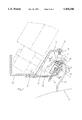
- FIG. 1 shows a cross-sectional view of the conveyor, perpendicular to the transport direction
- FIG. 2 is a side view of the conveyor, partially in cross-section
- FIG. 3 is a partial top view of the conveyor.
- the conveyor comprises a frame 7 that guides a chain 1, having two frame halves 7a and 7b. See FIG. 2.
- Chain 1 is a conventional roller chain.
- Individual chain links 2 have pushers 3 that project above chain 1 perpendicularly with respect to transport direction T. These pushers 3 have a triangular form and their front edges 3' which serve to contact the hanger hooks 20 are perpendicular to transport direction T.
- Transport direction T is defined by the circulation direction of chain 1.
- Chain 1 is driven by a drive motor 15 (FIG. 1) acting through a drive shaft 17 on drive pinion 16, said pinion being arranged in the frame half 7b (at the right in FIG. 2) in such fashion that the lower run 1" of chain 1 is guided over it.
- Frame 7 has a circumferential cut extending in its lengthwise direction in which chain 1 is guided. Chain 1 is likewise deflected at the ends of the frame 7 directly by the cut provided in frame 7.
- Frame 7 is divided into a front and a rear frame half 7a and 7b by a dividing gap 10 generally perpendicular or transverse to its lengthwise direction.
- FIG. 2 shows that each of the two frame halves 7a and 7b has a recess 5, 6 at its inner end which, as shown here, is formed by a blind hole.
- These two recesses 5 and 6 are opposite one another when the frame 7 is in the assembled state and bear a compression spring 4 whose two ends each abut one half of the frame.
- This compression spring 4 forces the two frame halves 7a and 7b apart along suitable guides, not shown here in greater detail. This produces an absolute tension on chain 1 which consequently is always driven without play.
- Pushers 3 are distributed at regular intervals on chain links 2 of chain 1. This provides a defined distance between the hangers 21 to be transported and a synchronization of the hangers 21, which is useful when, for example, transfer is to take place to another conveyor, such as the pockets of a high-speed conveyor in which only one conveyor pocket is provided for each hanger.
- the triangular pushers 3 are arranged offset relative to the lengthwise axis 18 of conveyor chain 1 in the direction of drive motor 15, as shown in FIG. 3. This means that the transporting force acting on hanger hooks 20 does not engage centrally of the hanger hooks and thereby sets hanger hooks 20 at an acute angle with respect to the chain 1 during transport, as shown in FIG. 3, which ensures improved transport stability.
- chain 1 is provided at an angle ⁇ to the horizontal A which is perpendicular to transport direction T.
- Slope angle ⁇ is advantageously chosen in such fashion that the conveyor, i.e. in particular drive pinion 16 and chain 1, is parallel to the bevel 20' of hook 20. It is advantageously 15-45 degrees. It is advantageous for the angles of incline of the chain 1 and the bevel 20' to be as close as possible. This arrangement leaves a maximum distance between drive pinion 16 and hanger 21 so that hanger hooks with a limited height can also be transported without problems, even when the hangers are swinging.
- frame 7 On its upper side, frame 7 has legs 8 and 9 surrounding the circumferential cut which run parallel to chain 1 on both sides. Legs 8 and 9 serve to support and guide hook 20. Height H 9 of leg 9, which is closer to the interior of hook 20, is greater than height H 8 of leg 8 which is closer to the tip of hook 20. The difference between heights H 8 and H 9 is chosen so that hanger 21 and/or hook 20 is guided in a horizontal plane despite the tilted position of the conveyor. End portions of the legs 8 and 9 (such as the inner edge of the leg 8 as shown in FIG. 1) may be bevelled or curved to match the curvature of the hook 20.
- the conveyor is mounted on metal brackets 22, 23 bent at an angle and integrated, in a manner not shown here in greater detail, into a conveyor system, for example the main conveyor line of the conveyor system.
- the attachment of frame 7 to bracket 23 is accomplished with several bolts 13.
- the front frame half 7a is arranged in elongated holes made in bracket 23, not shown here in greater detail.
- a protective strip 11 is mounted below a protective panel 19 that runs between the conveyor and drive motor 5.
- the protective strip 11 is mounted on protective panel 19 by several bolts 14 and compression springs 12 abutting the interior of protective strip 11 and protective panel 19, to be movable in the vertical direction.
- Protective strip 11 prevents injury to operating or maintenance personnel when the conveyor is running.
- the vertical mobility of protective strip 11 ensures that a hanger hook can be removed in simple fashion from the conveyor or, if necessary, inserted onto on the conveyor.
- Frame 7 is preferably made of plastic that exhibits self-lubricating properties with respect to chain 1. A thin film of lubricant is required only once so contamination of the articles of clothing being transported is effectively avoided and emergency running properties are improved.
Landscapes
- Engineering & Computer Science (AREA)
- Mechanical Engineering (AREA)
- Chain Conveyers (AREA)
- Structure Of Belt Conveyors (AREA)
- Intermediate Stations On Conveyors (AREA)
- Attitude Control For Articles On Conveyors (AREA)
Abstract
Description
Claims (20)
Applications Claiming Priority (2)
| Application Number | Priority Date | Filing Date | Title |
|---|---|---|---|
| DE4319164A DE4319164C2 (en) | 1993-06-09 | 1993-06-09 | Conveyors, in particular continuous conveyors for single brackets |
| DE4319164.9 | 1993-06-09 |
Publications (1)
| Publication Number | Publication Date |
|---|---|
| US5456346A true US5456346A (en) | 1995-10-10 |
Family
ID=6489995
Family Applications (1)
| Application Number | Title | Priority Date | Filing Date |
|---|---|---|---|
| US08/255,164 Expired - Fee Related US5456346A (en) | 1993-06-09 | 1994-06-07 | Continuous conveyor for transporting individual hangers |
Country Status (5)
| Country | Link |
|---|---|
| US (1) | US5456346A (en) |
| EP (1) | EP0628501B1 (en) |
| JP (1) | JPH0769426A (en) |
| AT (1) | ATE146152T1 (en) |
| DE (2) | DE4319164C2 (en) |
Cited By (7)
| Publication number | Priority date | Publication date | Assignee | Title |
|---|---|---|---|---|
| GB2331974A (en) * | 1997-12-05 | 1999-06-09 | Stockrail International Limite | Hanger conveyor system |
| US6460685B1 (en) * | 1999-03-03 | 2002-10-08 | Jensen Sweden Ab | Conveyor for garment hangers |
| US20030079641A1 (en) * | 2001-10-27 | 2003-05-01 | William Johnson | Power driven conveyor |
| US6609608B2 (en) * | 2001-07-04 | 2003-08-26 | PEP Fördertechnik GmbH | Drag catch conveyor |
| US6698575B2 (en) * | 2001-05-15 | 2004-03-02 | Franz Gartner | Installation for transporting objects on conveying paths by means of a conveying-comb-driven transporting roller |
| US20060027441A1 (en) * | 2004-08-04 | 2006-02-09 | Franz Gartner | System for transporting coat hangers |
| US11440748B2 (en) * | 2018-02-02 | 2022-09-13 | Ats Automation Tooling Systems Inc. | Linear motor conveyor system for clean/aseptic environments |
Families Citing this family (5)
| Publication number | Priority date | Publication date | Assignee | Title |
|---|---|---|---|---|
| CH689389A5 (en) * | 1995-03-31 | 1999-03-31 | Ferag Ag | Suction device. |
| DE19615773C2 (en) * | 1996-04-20 | 1998-06-04 | Duerkopp Adler Ag | Process for separating funding agencies |
| DE29621786U1 (en) | 1996-12-16 | 1997-03-27 | PEP Fördertechnik GmbH, 33609 Bielefeld | Ram pawl conveyor |
| DE102004002117B4 (en) * | 2004-01-14 | 2013-08-01 | Jostarndt Patentanwalts-Ag | Method and device for conveying workpieces in the field of processing machines |
| CN108363059B (en) * | 2017-12-28 | 2025-01-07 | 北京融创远大网络科技有限公司 | An intelligent vehicle-mounted radar device for reducing signal interference |
Citations (16)
| Publication number | Priority date | Publication date | Assignee | Title |
|---|---|---|---|---|
| US2146689A (en) * | 1937-02-12 | 1939-02-07 | Simon Abram | Belt conveyer |
| US3403767A (en) * | 1967-03-29 | 1968-10-01 | Rudolph F. Gerisch | Two-way switch means for conveyor system |
| DE7011838U (en) * | 1970-04-01 | 1971-05-19 | Loesch Gmbh Maschf | CONVEYOR CHAIN. |
| DE2121087A1 (en) * | 1970-06-01 | 1971-12-09 | Kornylac Co | Conveyor with guide tube and a conveyor belt running through the guide tube |
| DE2263330A1 (en) * | 1971-12-28 | 1973-07-12 | Cube Slide | MEMORY ARRANGEMENT |
| DE2506587A1 (en) * | 1974-02-28 | 1975-09-04 | Kornylac Co | Conveying hook shaped load carriers - has endless conveyor with transferring device engaging hooks of carriers |
| DE2606738A1 (en) * | 1975-02-19 | 1976-09-02 | Kornylac Co | ENDLESS CONVEYORS |
| DE3336190A1 (en) * | 1983-10-05 | 1985-05-02 | Fraunhofer-Gesellschaft zur Förderung der angewandten Forschung e.V., 8000 München | STOCK CHAIN CONVEYOR FOR HANGING STUECKGUETER |
| DE8809769U1 (en) * | 1988-08-01 | 1988-10-06 | Pavel, Wilfried, 33790 Halle | Chain conveyor for individual objects |
| EP0362936A1 (en) * | 1988-10-05 | 1990-04-11 | Geerts-Veen, Catharina Afien | Cable conveyor for light loads, in particular garments |
| DE9001627U1 (en) * | 1990-02-13 | 1990-04-26 | Wilfried Pavel Maschinenbau, 4802 Halle | Steep conveyors for individual objects, especially items of clothing to be transported hanging on hangers |
| DE9003620U1 (en) * | 1990-03-28 | 1990-07-26 | Banss Maschinenfabrik Gmbh & Co Kg, 35216 Biedenkopf | Slaughterhouse or meat cold storage conveyor |
| DE3929158A1 (en) * | 1989-09-02 | 1991-03-14 | Duerkopp Adler Ag | CONVEYOR |
| DE3929156A1 (en) * | 1989-09-02 | 1991-04-04 | Duerkopp Adler Ag | STORAGE CONVEYOR |
| DE9002594U1 (en) * | 1990-03-06 | 1991-06-20 | Veit Transpo GmbH, 86899 Landsberg | Overhead conveyor system |
| DE9210120U1 (en) * | 1992-07-28 | 1993-12-02 | Gärtner, Franz, 97656 Oberelsbach | Conveyor |
Family Cites Families (2)
| Publication number | Priority date | Publication date | Assignee | Title |
|---|---|---|---|---|
| US1639758A (en) * | 1925-02-12 | 1927-08-23 | Jervis B Webb | Overhead loading mechanism |
| DE3807280C1 (en) * | 1988-03-05 | 1989-05-24 | Sussman, Jennewein Bekleidungstechnik Gmbh, 6082 Moerfelden-Walldorf, De |
-
1993
- 1993-06-09 DE DE4319164A patent/DE4319164C2/en not_active Expired - Fee Related
-
1994
- 1994-03-25 DE DE59401238T patent/DE59401238D1/en not_active Expired - Lifetime
- 1994-03-25 EP EP94104754A patent/EP0628501B1/en not_active Expired - Lifetime
- 1994-03-25 AT AT94104754T patent/ATE146152T1/en not_active IP Right Cessation
- 1994-06-07 US US08/255,164 patent/US5456346A/en not_active Expired - Fee Related
- 1994-06-08 JP JP6126579A patent/JPH0769426A/en not_active Withdrawn
Patent Citations (16)
| Publication number | Priority date | Publication date | Assignee | Title |
|---|---|---|---|---|
| US2146689A (en) * | 1937-02-12 | 1939-02-07 | Simon Abram | Belt conveyer |
| US3403767A (en) * | 1967-03-29 | 1968-10-01 | Rudolph F. Gerisch | Two-way switch means for conveyor system |
| DE7011838U (en) * | 1970-04-01 | 1971-05-19 | Loesch Gmbh Maschf | CONVEYOR CHAIN. |
| DE2121087A1 (en) * | 1970-06-01 | 1971-12-09 | Kornylac Co | Conveyor with guide tube and a conveyor belt running through the guide tube |
| DE2263330A1 (en) * | 1971-12-28 | 1973-07-12 | Cube Slide | MEMORY ARRANGEMENT |
| DE2506587A1 (en) * | 1974-02-28 | 1975-09-04 | Kornylac Co | Conveying hook shaped load carriers - has endless conveyor with transferring device engaging hooks of carriers |
| DE2606738A1 (en) * | 1975-02-19 | 1976-09-02 | Kornylac Co | ENDLESS CONVEYORS |
| DE3336190A1 (en) * | 1983-10-05 | 1985-05-02 | Fraunhofer-Gesellschaft zur Förderung der angewandten Forschung e.V., 8000 München | STOCK CHAIN CONVEYOR FOR HANGING STUECKGUETER |
| DE8809769U1 (en) * | 1988-08-01 | 1988-10-06 | Pavel, Wilfried, 33790 Halle | Chain conveyor for individual objects |
| EP0362936A1 (en) * | 1988-10-05 | 1990-04-11 | Geerts-Veen, Catharina Afien | Cable conveyor for light loads, in particular garments |
| DE3929158A1 (en) * | 1989-09-02 | 1991-03-14 | Duerkopp Adler Ag | CONVEYOR |
| DE3929156A1 (en) * | 1989-09-02 | 1991-04-04 | Duerkopp Adler Ag | STORAGE CONVEYOR |
| DE9001627U1 (en) * | 1990-02-13 | 1990-04-26 | Wilfried Pavel Maschinenbau, 4802 Halle | Steep conveyors for individual objects, especially items of clothing to be transported hanging on hangers |
| DE9002594U1 (en) * | 1990-03-06 | 1991-06-20 | Veit Transpo GmbH, 86899 Landsberg | Overhead conveyor system |
| DE9003620U1 (en) * | 1990-03-28 | 1990-07-26 | Banss Maschinenfabrik Gmbh & Co Kg, 35216 Biedenkopf | Slaughterhouse or meat cold storage conveyor |
| DE9210120U1 (en) * | 1992-07-28 | 1993-12-02 | Gärtner, Franz, 97656 Oberelsbach | Conveyor |
Cited By (11)
| Publication number | Priority date | Publication date | Assignee | Title |
|---|---|---|---|---|
| GB2331974A (en) * | 1997-12-05 | 1999-06-09 | Stockrail International Limite | Hanger conveyor system |
| GB2331974B (en) * | 1997-12-05 | 2002-05-15 | Stockrail Internat Ltd | Improvements relating to conveyor systems |
| US6460685B1 (en) * | 1999-03-03 | 2002-10-08 | Jensen Sweden Ab | Conveyor for garment hangers |
| US6698575B2 (en) * | 2001-05-15 | 2004-03-02 | Franz Gartner | Installation for transporting objects on conveying paths by means of a conveying-comb-driven transporting roller |
| US6609608B2 (en) * | 2001-07-04 | 2003-08-26 | PEP Fördertechnik GmbH | Drag catch conveyor |
| US20030079641A1 (en) * | 2001-10-27 | 2003-05-01 | William Johnson | Power driven conveyor |
| US6889615B2 (en) | 2001-10-27 | 2005-05-10 | Bridgewater Products, Inc. | Power driven conveyor |
| WO2003095340A1 (en) * | 2002-05-10 | 2003-11-20 | Bridgewater Products, Inc. | Power driven conveyor |
| US20060027441A1 (en) * | 2004-08-04 | 2006-02-09 | Franz Gartner | System for transporting coat hangers |
| US7478722B2 (en) * | 2004-08-04 | 2009-01-20 | Gaertner Franz | System for transporting coat hangers |
| US11440748B2 (en) * | 2018-02-02 | 2022-09-13 | Ats Automation Tooling Systems Inc. | Linear motor conveyor system for clean/aseptic environments |
Also Published As
| Publication number | Publication date |
|---|---|
| DE4319164A1 (en) | 1994-12-15 |
| JPH0769426A (en) | 1995-03-14 |
| DE4319164C2 (en) | 1996-03-21 |
| DE59401238D1 (en) | 1997-01-23 |
| EP0628501B1 (en) | 1996-12-11 |
| ATE146152T1 (en) | 1996-12-15 |
| EP0628501A1 (en) | 1994-12-14 |
Similar Documents
| Publication | Publication Date | Title |
|---|---|---|
| US5456346A (en) | Continuous conveyor for transporting individual hangers | |
| US4802571A (en) | Apparatus for conveying suspended bottles | |
| US6109426A (en) | Oriented bottle conveyor | |
| US6991090B2 (en) | Suspension-conveyor diverter | |
| US5501316A (en) | Routing apparatus for a train of containers of glass or the like | |
| US4832179A (en) | Conveyor systems | |
| WO1997005049A1 (en) | Article combiner | |
| US5078262A (en) | Conveyor | |
| EP0275564B1 (en) | Conveyor assembly | |
| AU2017203325A1 (en) | Carriage for a rail-guided conveying system and conveying system comprising such a carriage | |
| EP0671349B1 (en) | Sorting device for discharging goods | |
| EP0132639B1 (en) | Conveyor apparatus | |
| US5064054A (en) | Overlapping flat surface transport carrier conveyor | |
| EP1187779B1 (en) | Conveyor for garment hangers | |
| US6029800A (en) | Conveyor for articles with wave-shaped rollers | |
| JPH10503160A (en) | Chain conveyor | |
| EP1161390B1 (en) | Conveyor for garment hanger | |
| AU2002301060B2 (en) | Device to assemble printed products by insertion | |
| US6168011B1 (en) | Accumulation conveyor system | |
| US6702276B2 (en) | Apparatus for reducing a stack of flat, flexible articles | |
| GB2128954A (en) | Apparatus for transforming a plurality of rows of articles, such as bottles, into a single row | |
| US6164438A (en) | Adjustable control roller apparatus and method | |
| US4090603A (en) | Collecting arrangement | |
| GR3005878T3 (en) | ||
| GB2074968A (en) | Improvements in or relating to a flexible conveyor belt supporting structure |
Legal Events
| Date | Code | Title | Description |
|---|---|---|---|
| AS | Assignment |
Owner name: DURKOPP ADLER AG A FOREIGN CORPORATION, GERMAN DE Free format text: ASSIGNMENT OF ASSIGNORS INTEREST;ASSIGNORS:SCHILLING, GERHARD;SCHNEUING, RALF;JANZEN, PAUL;REEL/FRAME:007094/0836;SIGNING DATES FROM 19940606 TO 19940630 |
|
| FEPP | Fee payment procedure |
Free format text: PAYOR NUMBER ASSIGNED (ORIGINAL EVENT CODE: ASPN); ENTITY STATUS OF PATENT OWNER: LARGE ENTITY |
|
| FPAY | Fee payment |
Year of fee payment: 4 |
|
| FEPP | Fee payment procedure |
Free format text: PAYOR NUMBER ASSIGNED (ORIGINAL EVENT CODE: ASPN); ENTITY STATUS OF PATENT OWNER: LARGE ENTITY Free format text: PAYER NUMBER DE-ASSIGNED (ORIGINAL EVENT CODE: RMPN); ENTITY STATUS OF PATENT OWNER: LARGE ENTITY |
|
| FPAY | Fee payment |
Year of fee payment: 8 |
|
| REMI | Maintenance fee reminder mailed | ||
| LAPS | Lapse for failure to pay maintenance fees | ||
| STCH | Information on status: patent discontinuation |
Free format text: PATENT EXPIRED DUE TO NONPAYMENT OF MAINTENANCE FEES UNDER 37 CFR 1.362 |
|
| FP | Lapsed due to failure to pay maintenance fee |
Effective date: 20071010 |