US5448323A - Close-up lens assembly incorporating a photo-ranging system - Google Patents
Close-up lens assembly incorporating a photo-ranging system Download PDFInfo
- Publication number
- US5448323A US5448323A US08/178,388 US17838893A US5448323A US 5448323 A US5448323 A US 5448323A US 17838893 A US17838893 A US 17838893A US 5448323 A US5448323 A US 5448323A
- Authority
- US
- United States
- Prior art keywords
- exposure
- camera
- light
- lens
- flash
- Prior art date
- Legal status (The legal status is an assumption and is not a legal conclusion. Google has not performed a legal analysis and makes no representation as to the accuracy of the status listed.)
- Expired - Lifetime
Links
Images


Classifications
-
- G—PHYSICS
- G03—PHOTOGRAPHY; CINEMATOGRAPHY; ANALOGOUS TECHNIQUES USING WAVES OTHER THAN OPTICAL WAVES; ELECTROGRAPHY; HOLOGRAPHY
- G03B—APPARATUS OR ARRANGEMENTS FOR TAKING PHOTOGRAPHS OR FOR PROJECTING OR VIEWING THEM; APPARATUS OR ARRANGEMENTS EMPLOYING ANALOGOUS TECHNIQUES USING WAVES OTHER THAN OPTICAL WAVES; ACCESSORIES THEREFOR
- G03B15/00—Special procedures for taking photographs; Apparatus therefor
- G03B15/02—Illuminating scene
- G03B15/03—Combinations of cameras with lighting apparatus; Flash units
- G03B15/05—Combinations of cameras with electronic flash apparatus; Electronic flash units
-
- G—PHYSICS
- G03—PHOTOGRAPHY; CINEMATOGRAPHY; ANALOGOUS TECHNIQUES USING WAVES OTHER THAN OPTICAL WAVES; ELECTROGRAPHY; HOLOGRAPHY
- G03B—APPARATUS OR ARRANGEMENTS FOR TAKING PHOTOGRAPHS OR FOR PROJECTING OR VIEWING THEM; APPARATUS OR ARRANGEMENTS EMPLOYING ANALOGOUS TECHNIQUES USING WAVES OTHER THAN OPTICAL WAVES; ACCESSORIES THEREFOR
- G03B19/00—Cameras
- G03B19/02—Still-picture cameras
- G03B19/04—Roll-film cameras
- G03B19/07—Roll-film cameras having more than one objective
-
- G—PHYSICS
- G03—PHOTOGRAPHY; CINEMATOGRAPHY; ANALOGOUS TECHNIQUES USING WAVES OTHER THAN OPTICAL WAVES; ELECTROGRAPHY; HOLOGRAPHY
- G03B—APPARATUS OR ARRANGEMENTS FOR TAKING PHOTOGRAPHS OR FOR PROJECTING OR VIEWING THEM; APPARATUS OR ARRANGEMENTS EMPLOYING ANALOGOUS TECHNIQUES USING WAVES OTHER THAN OPTICAL WAVES; ACCESSORIES THEREFOR
- G03B2215/00—Special procedures for taking photographs; Apparatus therefor
- G03B2215/05—Combinations of cameras with electronic flash units
- G03B2215/0503—Built-in units
-
- G—PHYSICS
- G03—PHOTOGRAPHY; CINEMATOGRAPHY; ANALOGOUS TECHNIQUES USING WAVES OTHER THAN OPTICAL WAVES; ELECTROGRAPHY; HOLOGRAPHY
- G03B—APPARATUS OR ARRANGEMENTS FOR TAKING PHOTOGRAPHS OR FOR PROJECTING OR VIEWING THEM; APPARATUS OR ARRANGEMENTS EMPLOYING ANALOGOUS TECHNIQUES USING WAVES OTHER THAN OPTICAL WAVES; ACCESSORIES THEREFOR
- G03B2215/00—Special procedures for taking photographs; Apparatus therefor
- G03B2215/05—Combinations of cameras with electronic flash units
- G03B2215/0564—Combinations of cameras with electronic flash units characterised by the type of light source
- G03B2215/0571—With second light source
Definitions
- This invention is related to a camera for close-up photography using a photo-ranging system to insure that the subject to be photographed is properly focused.
- the ranging system is used in combination with a selected one of a plurality of fixed focus lenses mounted at the front of the camera.
- Cameras having the capacity to take close-up photographs are not new.
- An example of a camera used for close-up photography is the Acmel Macro Auto V6 camera manufactured by Acmel Corporation of Tokyo, Japan which involves a highly complicated system involving focal beams and a plurality of detachable lenses for different focal lengths. Each detachable lens is designed for a single subject distance.
- the resulting camera serves its purpose but is altogether too complicated for easy use by a camera operator. It is both bulky and heavy, weighing about 41/2 pounds.
- U.S. Pat. No. 4,777,501 discloses a single pair of laser ranging lights of different wavelengths mounted to project converging light beams at the focal point of a single fixed focus exposure lens of the associated camera.
- U.S. Pat. No. 4,914,460 discloses a single pair of light sources each of which projects a plurality of light beams in a particular pattern.
- the pattern is displayed on a surface which allows an observer to determine the topography of the surface and its distance from an associated camera.
- the camera is mounted equidistant between the two light sources.
- U.S. Pat. No. 5,142,299 discloses an underwater camera mounted between a pair of light sources.
- the light sources project light beams to converge at the focal point of a single fixed focus lens system of the associated camera.
- This invention solves that problem, in that, it incorporates a plurality of exposure lenses in a turret mounted on the front of the camera.
- the turret is mounted to rotate about an axis generally perpendicular to a line extending from the focal point of the exposure lens to the center of the exposure lens itself (i.e., the optical axis of the exposure lens).
- Each of the plurality of exposure lenses is of a different fixed focal length and magnification, from the other exposure lenses.
- the selected focal lengths listed subsequently are believed to be most frequently desirable for typical close-up photography for which this camera is designed.
- Each exposure lens in the camera is combined with a pair of combination ranging light lens and prisms which are located on the turret diagonally across from each other on each side of the associated exposure lens.
- a combination of said transversely mounted prism-lenses and ranging lights are permanently focused and oriented to direct beams of light which intersect the axis of the exposure lens system.
- the two converging light beams may be observed visually at the sharpest subject focus distance of the exposure lens system.
- the photographer may simply observe the impinging beams of light from the two transversely mounted ranging lights as they impinge on the subject.
- a single spot of light existing on the subject formed by the two converging light beams indicates the subject is in focus through the exposure lens system.
- Two spots of light or a noncircular or oblong pattern indicates the subject is out of focus. Getting the subject in proper focus is achieved by moving the camera and/or rotating the turret to align a different exposure lens together with their associated ranging light lenses and prisms.
- Each pair of ranging lights is coordinated with a single fixed focus exposure lens such that convergence of the light beams of the ranging lights occurs at the sharpest subject focus distance of the associated exposure lens.
- the photographer may manually select a desired focus distance by selecting the appropriate exposure lens and selection is made by rotating the turret.
- the combined pair of lenses for directing the ranging light beams are fixed in place on the turret and automatically move into operative position as the turret stops at the selected exposure lens.
- FIG. 1 is a perspective view of a camera having a plurality of exposure lenses and ranging light lenses mounted for selective use on a turret according to this invention
- FIG. 2 is a fragmentary perspective view of the turret, light and lens orientation of the camera of FIG. 1;
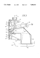
- FIG. 3 is a fragmentary sectional view of the general orientation of the camera, adjustable turret, lens and lighting combination of the invention.
- FIG. 4 is a block diagram of the manual select switch and turret position control of the strobe lights in the close-up camera of the present invention.
- This invention includes a camera 10 having an upper housing 12 and a lower housing 14 as shown in FIG. 1.
- the upper housing 12 encloses the lenses, lighting and the like.
- the lower housing 14 is preferably mounted to the upper housing 12 by a hinge (not shown) to allow it to swing away from the upper housing 12 for insertion of a cassette of film units to be mounted therein for later exposure.
- FIG. 1 shows an outlet slot 16 in lower housing 14 which is suitable for the expulsion of exposed film units of the instant photography type
- this invention is not limited to instant photography. It is however specifically intended for close-up photography involving flash units and converging light beams to serve as the ranging system for proper focus of the exposure lens.
- FIG. 1 illustrates the camera 10 having a pair of hand grips 18 (only one being shown) to allow easy manual support for the camera.
- the front 20 of the camera 10 includes a plurality of apertures including a pair of rectangular openings 22, 24 to accommodate lenses 26, 28.
- Lenses 26, 28 focus beams of light 30, 32 (FIG. 3), respectively, at a particular point forward of camera front 20 corresponding to the sharpest subject focus distance of an exposure lens 34 mounted in opening 36 equidistant between a pair of flash or strobe units 38, 40.
- a turret 42 is mounted adjacent front face 20 for adjusting the camera to a desired focus distance.
- An adjusting dial or knob 44 projects upwardly from the top of upper housing 12 and is in suitable position for easy manual operation. Rotation of dial 44 rotates the light beam focusing lenses 26, 28 and the exposure lenses 34 about an axis 46 which allows for the placement of the desired light beam focusing lenses and exposure lens combination into a desired position. It will be observed that the flash units 38, 40 remain stationary in opening 36 while each set of three lenses shifts into operative position. That is, there are five different exposure lenses 34 which may be adjusted into operable position by rotating knob 44 and each lens 34 has a different fixed focal length.
- Each exposure lens 34 is supported in combination equidistant between a pair of light focusing ranging lenses 26, 28.
- Each pair of ranging lenses 26, 28 is coordinated with its associated exposure lens 34 such that the directed beams of light 30, 32 converge at the sharpest subject focus distance of the associated exposure lens 34.
- light beams 30, 32 are circular in their projection and at the focus of the associated exposure lens 34, the beams converge to a single circular pattern.
- the camera operator views the subject to be photographed through an eyepiece 48 oriented with a viewing optical system 50 and a pair of mirrors 52, 54 such that the operator sees the subject to be photographed along a viewing path coaxial with the optical axis of the exposure lens 34. Should the operator observe the ranging lights forming an egg shaped pattern or two separate circles, the camera must be moved closer or further away from the subject to get to the focus point where the pattern becomes a single circular spot and a subject thereat will be in focus.
- a photographic film unit 56 in lower housing 14 is aligned with a passageway 58 in camera 10 having a mirror 60 oriented to reflect light entering the camera through exposure lens 34 onto a light sensitive surface of the film unit 56.
- FIG. 3 illustration shows a pivotable shutter 62 blocking the light passageway 58 between film unit 56 and exposure lens 34.
- Shutter 62 supports mirror 54 to reflect light into the viewing passageway 50 toward eyepiece 48.
- a conventional mechanism automatically deflects shutter 62 upward and then back to its initial light blocking position to generate an exposure interval whenever the shutter is actuated.
- Such structure is not illustrated as it is well known in the art.
- Ranging light sources 64, 66 are illustrated as being stationary such that only two are needed. To get the proper focus, prisms 68 are formed in ranging light ranging lenses 26, 28 to direct beams 30, 32 correctly. In fact, the ranging lights 64, 66 may be oriented such that ranging lens 26, 28 are unnecessary in use with one of the five exposure lens 34, whereas, the other four sets of ranging light focusing lenses require specially structured lenses to property focus the ranging lights 64, 66.
- the ranging lenses 26, 28 are shown as fresnel lenses for compactness and ease of manufacture.
- the source of light for ranging lenses 26, 28 may be a single light or a plurality of lights if desired but, the preferred embodiment uses two sources as illustrated.
- the levels of magnification and their associated subject distances for exposure lens 34 are 3 ⁇ @3.4 in.; 2 ⁇ @5.1 in.; 1 ⁇ @10.2 in.; 0.4 ⁇ @25.8 in.; and 0.2 ⁇ @51.7 in. It will be quite clear that these magnifications and subject distances are only preferred examples and any desirable different parameters may be used without departing from the inventive concept.
- the structure illustrating the invention shows the axis 46 of the turret to be vertical. It could as easily be horizontal.
- the duration of the light output from the pair of strobe lights 38, 40 is dependent upon the particular subject distance and relative aperture (f-number) of an exposure lens 34 which is in operative position at the time of taking a photograph.
- the duration of lighting by the strobe lights 38, 40 is controlled automatically when the desired exposure lens 34 is positioned to its operative position by rotating knob 44 and no separate adjustment is necessary, it being controlled within the camera mechanism itself in a manner well known in the art as functionality depicted in the block diagram of FIG. 4.
- a photographer observes the subject to be photographed through eyepiece 48 after an adjustment has been made of the knob 44 to place the appropriate exposure lens 34 in operative position.
- the desired exposure lens 34 is based on subject distance and the degree of magnification desired by the photographer.
- indicia associated with knob 44 assists the photographer in this determination.
- Adjusting the desired exposure lens 34 into operative position automatically locates the proper pair of ranging light focusing lenses 26, 28 into proper position to direct light beams 30, 32 to converge at the sharpest subject focus distance of exposure lens 34.
- the operator views the subject through eyepiece 48 and may also observe the light pattern from light beams 30, 32 impinging on the subject. If the light pattern is a single circle, the subject is in focus with exposure lens 34 and the shutter 62 may be actuated.
- Strobe lights 38, 40 operate in the manner built into the camera structure and may or may not be based on a quenching or adjustable duration of light. Indeed, as shown in FIG. 4, the preferred embodiment may include a switch to disenable one or both of strobe lights 38, 40 at the discretion of the photographer. This may be a desirable feature depending upon the effect the photographer is trying to achieve.
- the particular feature of this invention which distinguishes it from products on the market is its simplicity and low cost for close-up photography.
- the turret mechanism described herein allows a plurality of different fixed focal length exposure lenses 34 together with their corresponding light beam focusing lenses of a photo-imaging system to be adjusted into and out of operative position by an easy manual operation not elsewhere available.
Abstract
Description
Claims (15)
Priority Applications (6)
| Application Number | Priority Date | Filing Date | Title |
|---|---|---|---|
| US08/178,388 US5448323A (en) | 1993-12-23 | 1993-12-23 | Close-up lens assembly incorporating a photo-ranging system |
| JP6319822A JPH0850228A (en) | 1993-12-23 | 1994-12-22 | Camera with close-up lens assembly in which optical range finder is incorporated |
| EP94309881A EP0661584B1 (en) | 1993-12-23 | 1994-12-22 | Lens assembly incorporating a photo-ranging system |
| DE69423324T DE69423324T2 (en) | 1993-12-23 | 1994-12-22 | Lens arrangement with distance measuring system |
| CA002138908A CA2138908C (en) | 1993-12-23 | 1994-12-22 | Close-up lens assembly incorporating a photo-ranging system |
| ES94309881T ES2142914T3 (en) | 1993-12-23 | 1994-12-22 | LENSES ARRANGEMENT INCORPORATED IN A PHOTO-DETERMINATION SYSTEM. |
Applications Claiming Priority (1)
| Application Number | Priority Date | Filing Date | Title |
|---|---|---|---|
| US08/178,388 US5448323A (en) | 1993-12-23 | 1993-12-23 | Close-up lens assembly incorporating a photo-ranging system |
Publications (1)
| Publication Number | Publication Date |
|---|---|
| US5448323A true US5448323A (en) | 1995-09-05 |
Family
ID=22652357
Family Applications (1)
| Application Number | Title | Priority Date | Filing Date |
|---|---|---|---|
| US08/178,388 Expired - Lifetime US5448323A (en) | 1993-12-23 | 1993-12-23 | Close-up lens assembly incorporating a photo-ranging system |
Country Status (6)
| Country | Link |
|---|---|
| US (1) | US5448323A (en) |
| EP (1) | EP0661584B1 (en) |
| JP (1) | JPH0850228A (en) |
| CA (1) | CA2138908C (en) |
| DE (1) | DE69423324T2 (en) |
| ES (1) | ES2142914T3 (en) |
Cited By (26)
| Publication number | Priority date | Publication date | Assignee | Title |
|---|---|---|---|---|
| US5697003A (en) * | 1996-06-28 | 1997-12-09 | Eastman Kodak Company | Camera with combination multi-lamp flash source and exposure counter |
| US5729773A (en) * | 1996-06-28 | 1998-03-17 | Eastman Kodak Company | Camera with multi-lamp flash wheel |
| US5956536A (en) * | 1996-08-21 | 1999-09-21 | Polaroid Corporation | Camera optical accessories therefor and method of use |
| US6184534B1 (en) | 1998-08-04 | 2001-02-06 | Eastman Kodak Company | Method of pulsing light emitting diodes for reading fluorescent indicia, data reader, and system |
| US6191406B1 (en) | 1998-07-24 | 2001-02-20 | Eastman Kodak Company | Data reader and reader system having visible centerless targeting |
| US6339680B1 (en) * | 2000-01-10 | 2002-01-15 | Jaquelynne Mauvais | Selectable multi-lens disposable camera |
| US6700613B1 (en) | 1998-06-16 | 2004-03-02 | Eastman Kodak Company | Data-reading image capture apparatus, camera, and method of use |
| US20040201980A1 (en) * | 2003-04-11 | 2004-10-14 | Ultradent Products, Inc. | Illumination apparatus for enhancing visibility of oral tissues |
| US6890175B2 (en) | 2002-12-18 | 2005-05-10 | Ultradent Products, Inc. | Cooling system for hand-held curing light |
| US6940659B2 (en) | 2002-01-11 | 2005-09-06 | Ultradent Products, Inc. | Cone-shaped lens having increased forward light intensity and kits incorporating such lenses |
| US6994546B2 (en) | 2002-12-18 | 2006-02-07 | Ultradent Products, Inc. | Light curing device with detachable power supply |
| US7056116B2 (en) | 2004-10-26 | 2006-06-06 | Ultradent Products, Inc. | Heat sink for dental curing light comprising a plurality of different materials |
| US7074040B2 (en) | 2004-03-30 | 2006-07-11 | Ultradent Products, Inc. | Ball lens for use with a dental curing light |
| US7106523B2 (en) | 2002-01-11 | 2006-09-12 | Ultradent Products, Inc. | Optical lens used to focus led light |
| US20060263081A1 (en) * | 2005-05-20 | 2006-11-23 | Polaroid Corporation | Photographic strobe diffuser |
| US7144250B2 (en) | 2003-12-17 | 2006-12-05 | Ultradent Products, Inc. | Rechargeable dental curing light |
| US20070020578A1 (en) * | 2005-07-19 | 2007-01-25 | Scott Robert R | Dental curing light having a short wavelength LED and a fluorescing lens for converting wavelength light to curing wavelengths and related method |
| US7192276B2 (en) | 2003-08-20 | 2007-03-20 | Ultradent Products, Inc. | Dental curing light adapted to emit light at a desired angle |
| US7195482B2 (en) | 2003-12-30 | 2007-03-27 | Ultradent Products, Inc. | Dental curing device having a heat sink for dissipating heat |
| US20090091651A1 (en) * | 2007-10-09 | 2009-04-09 | Eyal Artsiely | Dual camera apparatus |
| US20100123819A1 (en) * | 2008-11-14 | 2010-05-20 | Primax Electronics Ltd. | Portable camera having lens assembly switching mechanism |
| US20110058800A1 (en) * | 2009-09-07 | 2011-03-10 | Samsung Electronics Co., Ltd. | Humanoid robot recognizing objects using a camera module and method thereof |
| US8568140B2 (en) | 1998-01-20 | 2013-10-29 | Jozef Kovac | Apparatus and method for curing materials with radiation |
| US9066777B2 (en) | 2009-04-02 | 2015-06-30 | Kerr Corporation | Curing light device |
| US9072572B2 (en) | 2009-04-02 | 2015-07-07 | Kerr Corporation | Dental light device |
| CN105223685A (en) * | 2015-10-29 | 2016-01-06 | 国网北京市电力公司 | A kind of view finder extends eyepiece |
Families Citing this family (1)
| Publication number | Priority date | Publication date | Assignee | Title |
|---|---|---|---|---|
| EP2185954A1 (en) * | 2007-09-07 | 2010-05-19 | Datalogic Scanning Group S.r.l. | Image acquisition device and optical component thereof |
Citations (6)
| Publication number | Priority date | Publication date | Assignee | Title |
|---|---|---|---|---|
| US3416426A (en) * | 1966-09-29 | 1968-12-17 | Polaroid Corp | Photographic apparatus with rangefinder-aperture control |
| US3418908A (en) * | 1966-09-06 | 1968-12-31 | Polaroid Corp | Range finding-focusing apparatus for a photographic camera |
| US4777501A (en) * | 1987-04-20 | 1988-10-11 | Harbor Branch Oceanographic Institution, Inc. | Underwater optical methods and apparatus |
| US4828383A (en) * | 1985-11-11 | 1989-05-09 | Olympus Optical Co., Ltd. | Range-finding optical system |
| US4914460A (en) * | 1987-05-29 | 1990-04-03 | Harbor Branch Oceanographic Institution Inc. | Apparatus and methods of determining distance and orientation |
| US5142299A (en) * | 1991-10-15 | 1992-08-25 | Braun Photo-Aquatic Systems | Hand held system for close-range underwater photography composing and focusing |
Family Cites Families (5)
| Publication number | Priority date | Publication date | Assignee | Title |
|---|---|---|---|---|
| US3185061A (en) * | 1962-08-13 | 1965-05-25 | Leonard F Westphalen | Multifocal camera |
| JPS5325422A (en) * | 1976-08-20 | 1978-03-09 | West Electric Co | Variable focal length flash camera |
| US4887107A (en) * | 1986-07-29 | 1989-12-12 | Minolta Camera Kabushiki Kaisha | Camera |
| JPH0293443A (en) * | 1988-09-29 | 1990-04-04 | Asahi Optical Co Ltd | Stroboscopic driving device for zoom lens camera |
| US5019845A (en) * | 1989-06-23 | 1991-05-28 | Olympus Optical Co., Ltd. | Flash device for camera |
-
1993
- 1993-12-23 US US08/178,388 patent/US5448323A/en not_active Expired - Lifetime
-
1994
- 1994-12-22 CA CA002138908A patent/CA2138908C/en not_active Expired - Fee Related
- 1994-12-22 JP JP6319822A patent/JPH0850228A/en active Pending
- 1994-12-22 ES ES94309881T patent/ES2142914T3/en not_active Expired - Lifetime
- 1994-12-22 EP EP94309881A patent/EP0661584B1/en not_active Expired - Lifetime
- 1994-12-22 DE DE69423324T patent/DE69423324T2/en not_active Expired - Fee Related
Patent Citations (6)
| Publication number | Priority date | Publication date | Assignee | Title |
|---|---|---|---|---|
| US3418908A (en) * | 1966-09-06 | 1968-12-31 | Polaroid Corp | Range finding-focusing apparatus for a photographic camera |
| US3416426A (en) * | 1966-09-29 | 1968-12-17 | Polaroid Corp | Photographic apparatus with rangefinder-aperture control |
| US4828383A (en) * | 1985-11-11 | 1989-05-09 | Olympus Optical Co., Ltd. | Range-finding optical system |
| US4777501A (en) * | 1987-04-20 | 1988-10-11 | Harbor Branch Oceanographic Institution, Inc. | Underwater optical methods and apparatus |
| US4914460A (en) * | 1987-05-29 | 1990-04-03 | Harbor Branch Oceanographic Institution Inc. | Apparatus and methods of determining distance and orientation |
| US5142299A (en) * | 1991-10-15 | 1992-08-25 | Braun Photo-Aquatic Systems | Hand held system for close-range underwater photography composing and focusing |
Cited By (35)
| Publication number | Priority date | Publication date | Assignee | Title |
|---|---|---|---|---|
| US5729773A (en) * | 1996-06-28 | 1998-03-17 | Eastman Kodak Company | Camera with multi-lamp flash wheel |
| US5697003A (en) * | 1996-06-28 | 1997-12-09 | Eastman Kodak Company | Camera with combination multi-lamp flash source and exposure counter |
| US5956536A (en) * | 1996-08-21 | 1999-09-21 | Polaroid Corporation | Camera optical accessories therefor and method of use |
| US9622839B2 (en) | 1998-01-20 | 2017-04-18 | Kerr Corporation | Apparatus and method for curing materials with radiation |
| US8568140B2 (en) | 1998-01-20 | 2013-10-29 | Jozef Kovac | Apparatus and method for curing materials with radiation |
| US9572643B2 (en) | 1998-01-20 | 2017-02-21 | Kerr Corporation | Apparatus and method for curing materials with radiation |
| US6700613B1 (en) | 1998-06-16 | 2004-03-02 | Eastman Kodak Company | Data-reading image capture apparatus, camera, and method of use |
| US6191406B1 (en) | 1998-07-24 | 2001-02-20 | Eastman Kodak Company | Data reader and reader system having visible centerless targeting |
| US6184534B1 (en) | 1998-08-04 | 2001-02-06 | Eastman Kodak Company | Method of pulsing light emitting diodes for reading fluorescent indicia, data reader, and system |
| US6339680B1 (en) * | 2000-01-10 | 2002-01-15 | Jaquelynne Mauvais | Selectable multi-lens disposable camera |
| US6940659B2 (en) | 2002-01-11 | 2005-09-06 | Ultradent Products, Inc. | Cone-shaped lens having increased forward light intensity and kits incorporating such lenses |
| US7106523B2 (en) | 2002-01-11 | 2006-09-12 | Ultradent Products, Inc. | Optical lens used to focus led light |
| US6890175B2 (en) | 2002-12-18 | 2005-05-10 | Ultradent Products, Inc. | Cooling system for hand-held curing light |
| US6994546B2 (en) | 2002-12-18 | 2006-02-07 | Ultradent Products, Inc. | Light curing device with detachable power supply |
| US6957907B2 (en) | 2003-04-11 | 2005-10-25 | Ultradent Products, Inc. | Illumination apparatus having a light-converting lens for increasing visual contrast between different oral tissues |
| US20040201980A1 (en) * | 2003-04-11 | 2004-10-14 | Ultradent Products, Inc. | Illumination apparatus for enhancing visibility of oral tissues |
| US7192276B2 (en) | 2003-08-20 | 2007-03-20 | Ultradent Products, Inc. | Dental curing light adapted to emit light at a desired angle |
| US7144250B2 (en) | 2003-12-17 | 2006-12-05 | Ultradent Products, Inc. | Rechargeable dental curing light |
| US7195482B2 (en) | 2003-12-30 | 2007-03-27 | Ultradent Products, Inc. | Dental curing device having a heat sink for dissipating heat |
| US7074040B2 (en) | 2004-03-30 | 2006-07-11 | Ultradent Products, Inc. | Ball lens for use with a dental curing light |
| US7056116B2 (en) | 2004-10-26 | 2006-06-06 | Ultradent Products, Inc. | Heat sink for dental curing light comprising a plurality of different materials |
| US20060263081A1 (en) * | 2005-05-20 | 2006-11-23 | Polaroid Corporation | Photographic strobe diffuser |
| US7257322B2 (en) | 2005-05-20 | 2007-08-14 | Staller Norman D | Photographic strobe diffuser |
| US20070020578A1 (en) * | 2005-07-19 | 2007-01-25 | Scott Robert R | Dental curing light having a short wavelength LED and a fluorescing lens for converting wavelength light to curing wavelengths and related method |
| US8279327B2 (en) * | 2007-10-09 | 2012-10-02 | Eyal Artsiely | Dual camera apparatus |
| US20090091651A1 (en) * | 2007-10-09 | 2009-04-09 | Eyal Artsiely | Dual camera apparatus |
| US20100123819A1 (en) * | 2008-11-14 | 2010-05-20 | Primax Electronics Ltd. | Portable camera having lens assembly switching mechanism |
| US8077254B2 (en) * | 2008-11-14 | 2011-12-13 | Primax Electronics Ltd. | Portable camera having lens assembly switching mechanism |
| US9066777B2 (en) | 2009-04-02 | 2015-06-30 | Kerr Corporation | Curing light device |
| US9072572B2 (en) | 2009-04-02 | 2015-07-07 | Kerr Corporation | Dental light device |
| US9693846B2 (en) | 2009-04-02 | 2017-07-04 | Kerr Corporation | Dental light device |
| US9730778B2 (en) | 2009-04-02 | 2017-08-15 | Kerr Corporation | Curing light device |
| US9987110B2 (en) | 2009-04-02 | 2018-06-05 | Kerr Corporation | Dental light device |
| US20110058800A1 (en) * | 2009-09-07 | 2011-03-10 | Samsung Electronics Co., Ltd. | Humanoid robot recognizing objects using a camera module and method thereof |
| CN105223685A (en) * | 2015-10-29 | 2016-01-06 | 国网北京市电力公司 | A kind of view finder extends eyepiece |
Also Published As
| Publication number | Publication date |
|---|---|
| DE69423324D1 (en) | 2000-04-13 |
| DE69423324T2 (en) | 2000-07-27 |
| EP0661584A1 (en) | 1995-07-05 |
| EP0661584B1 (en) | 2000-03-08 |
| CA2138908A1 (en) | 1995-06-24 |
| JPH0850228A (en) | 1996-02-20 |
| ES2142914T3 (en) | 2000-05-01 |
| CA2138908C (en) | 1999-01-26 |
Similar Documents
| Publication | Publication Date | Title |
|---|---|---|
| US5448323A (en) | Close-up lens assembly incorporating a photo-ranging system | |
| JP2666142B2 (en) | Automatic focus detection device for camera | |
| US7391966B2 (en) | Selective focus system for use in photography | |
| US5382988A (en) | Stereoscopic retinal camera with focus detection system | |
| US4081809A (en) | Viewfinder system for a large camera | |
| EP1094349B1 (en) | Focusing apparatus for image recording system | |
| US4757372A (en) | SLR zoom camera | |
| US4487490A (en) | Instantaneous three-dimensional camera | |
| US3622242A (en) | Stereoscopic rangefinder with movable reticles | |
| JPS62118328A (en) | Automatic power varying camera | |
| US3914034A (en) | Camera system, especially motion picture camera system with interchangeable lenses | |
| US4429964A (en) | Mirror-reflex camera with electronic rangefinder | |
| US4908640A (en) | Apparatus for taking photograph with monitoring system | |
| US4198144A (en) | Eye fundus camera | |
| JPH0264513A (en) | Camera with viewing line inputting device | |
| US4428653A (en) | Mirror reflex camera with an electronic range finder | |
| JPH0772765B2 (en) | Camera automatic focusing device | |
| JPH04267230A (en) | Camera having line-of-sight detecting device | |
| US3519342A (en) | Range finder focusing device | |
| JPS5928424Y2 (en) | Stereo photography lens device that can be attached to and detached from the camera body | |
| EP0793136B1 (en) | Optical apparatus such as a camera | |
| JP3272636B2 (en) | Camera viewfinder device | |
| JP3272635B2 (en) | Camera viewfinder device | |
| JPH05333405A (en) | Finder device | |
| JPH05188431A (en) | Finder complying with panoramic photographing |
Legal Events
| Date | Code | Title | Description |
|---|---|---|---|
| AS | Assignment |
Owner name: POLAROID CORPORATION, MASSACHUSETTS Free format text: ASSIGNMENT OF ASSIGNORS INTEREST;ASSIGNORS:SORLI, DUNCAN C.;CLARK, PETER P.;REEL/FRAME:006925/0918;SIGNING DATES FROM 19940207 TO 19940208 |
|
| STCF | Information on status: patent grant |
Free format text: PATENTED CASE |
|
| FPAY | Fee payment |
Year of fee payment: 4 |
|
| AS | Assignment |
Owner name: MORGAN GUARANTY TRUST COMPANY OF NEW YORK, NEW YOR Free format text: SECURITY AGREEMENT;ASSIGNOR:POLAROID CORPORATION;REEL/FRAME:011658/0699 Effective date: 20010321 |
|
| FPAY | Fee payment |
Year of fee payment: 8 |
|
| AS | Assignment |
Owner name: OEP IMAGINIG OPERATING CORPORATION, NEW YORK Free format text: ASSIGNMENT OF ASSIGNORS INTEREST;ASSIGNOR:POLAROID CORPORATION;REEL/FRAME:016427/0144 Effective date: 20020731 Owner name: POLAROID CORPORATION, NEW YORK Free format text: CHANGE OF NAME;ASSIGNOR:OEP IMAGING OPERATING CORPORATION;REEL/FRAME:016470/0006 Effective date: 20020801 Owner name: OEP IMAGINIG OPERATING CORPORATION,NEW YORK Free format text: ASSIGNMENT OF ASSIGNORS INTEREST;ASSIGNOR:POLAROID CORPORATION;REEL/FRAME:016427/0144 Effective date: 20020731 Owner name: POLAROID CORPORATION,NEW YORK Free format text: CHANGE OF NAME;ASSIGNOR:OEP IMAGING OPERATING CORPORATION;REEL/FRAME:016470/0006 Effective date: 20020801 |
|
| AS | Assignment |
Owner name: WILMINGTON TRUST COMPANY, AS COLLATERAL AGENT, DEL Free format text: ASSIGNMENT OF ASSIGNORS INTEREST;ASSIGNORS:POLAROLD HOLDING COMPANY;POLAROID CORPORATION;POLAROID ASIA PACIFIC LLC;AND OTHERS;REEL/FRAME:016602/0332 Effective date: 20050428 Owner name: JPMORGAN CHASE BANK,N.A,AS ADMINISTRATIVE AGENT, W Free format text: SECURITY INTEREST;ASSIGNORS:POLAROID HOLDING COMPANY;POLAROID CORPORATION;POLAROID ASIA PACIFIC LLC;AND OTHERS;REEL/FRAME:016602/0603 Effective date: 20050428 Owner name: WILMINGTON TRUST COMPANY, AS COLLATERAL AGENT,DELA Free format text: SECURITY AGREEMENT;ASSIGNORS:POLAROLD HOLDING COMPANY;POLAROID CORPORATION;POLAROID ASIA PACIFIC LLC;AND OTHERS;REEL/FRAME:016602/0332 Effective date: 20050428 Owner name: JPMORGAN CHASE BANK,N.A,AS ADMINISTRATIVE AGENT,WI Free format text: SECURITY INTEREST;ASSIGNORS:POLAROID HOLDING COMPANY;POLAROID CORPORATION;POLAROID ASIA PACIFIC LLC;AND OTHERS;REEL/FRAME:016602/0603 Effective date: 20050428 Owner name: WILMINGTON TRUST COMPANY, AS COLLATERAL AGENT, DEL Free format text: SECURITY AGREEMENT;ASSIGNORS:POLAROLD HOLDING COMPANY;POLAROID CORPORATION;POLAROID ASIA PACIFIC LLC;AND OTHERS;REEL/FRAME:016602/0332 Effective date: 20050428 |
|
| AS | Assignment |
Owner name: POLAROID CORPORATION (F/K/A OEP IMAGING OPERATING Free format text: U.S. BANKRUPTCY COURT DISTRICT OF DELAWARE ORDER AUTHORIZING RELEASE OF ALL LIENS;ASSIGNOR:JPMORGAN CHASE BANK, N.A. (F/K/A MORGAN GUARANTY TRUST COMPANY OF NEW YORK);REEL/FRAME:016621/0377 Effective date: 20020418 |
|
| AS | Assignment |
Owner name: OEP IMAGING OPERATING CORPORATION,NEW YORK Free format text: ASSIGNMENT OF ASSIGNORS INTEREST;ASSIGNOR:POLAROID CORPORATION;REEL/FRAME:018584/0600 Effective date: 20020731 Owner name: OEP IMAGING OPERATING CORPORATION, NEW YORK Free format text: ASSIGNMENT OF ASSIGNORS INTEREST;ASSIGNOR:POLAROID CORPORATION;REEL/FRAME:018584/0600 Effective date: 20020731 |
|
| AS | Assignment |
Owner name: POLAROID CORPORATION (FMR OEP IMAGING OPERATING CO Free format text: SUPPLEMENTAL ASSIGNMENT OF PATENTS;ASSIGNOR:PRIMARY PDC, INC. (FMR POLAROID CORPORATION);REEL/FRAME:019077/0001 Effective date: 20070122 |
|
| REMI | Maintenance fee reminder mailed | ||
| FPAY | Fee payment |
Year of fee payment: 12 |
|
| SULP | Surcharge for late payment |
Year of fee payment: 11 |
|
| AS | Assignment |
Owner name: POLAROID HOLDING COMPANY, MASSACHUSETTS Free format text: RELEASE OF SECURITY INTEREST IN PATENTS;ASSIGNOR:WILMINGTON TRUST COMPANY;REEL/FRAME:019699/0512 Effective date: 20070425 Owner name: POLAROID CORPORATION, MASSACHUSETTS Free format text: RELEASE OF SECURITY INTEREST IN PATENTS;ASSIGNOR:WILMINGTON TRUST COMPANY;REEL/FRAME:019699/0512 Effective date: 20070425 Owner name: POLAROID CAPITAL LLC, MASSACHUSETTS Free format text: RELEASE OF SECURITY INTEREST IN PATENTS;ASSIGNOR:WILMINGTON TRUST COMPANY;REEL/FRAME:019699/0512 Effective date: 20070425 Owner name: POLAROID ASIA PACIFIC LLC, MASSACHUSETTS Free format text: RELEASE OF SECURITY INTEREST IN PATENTS;ASSIGNOR:WILMINGTON TRUST COMPANY;REEL/FRAME:019699/0512 Effective date: 20070425 Owner name: POLAROID EYEWEAR LLC, MASSACHUSETTS Free format text: RELEASE OF SECURITY INTEREST IN PATENTS;ASSIGNOR:WILMINGTON TRUST COMPANY;REEL/FRAME:019699/0512 Effective date: 20070425 Owner name: POLOROID INTERNATIONAL HOLDING LLC, MASSACHUSETTS Free format text: RELEASE OF SECURITY INTEREST IN PATENTS;ASSIGNOR:WILMINGTON TRUST COMPANY;REEL/FRAME:019699/0512 Effective date: 20070425 Owner name: POLAROID INVESTMENT LLC, MASSACHUSETTS Free format text: RELEASE OF SECURITY INTEREST IN PATENTS;ASSIGNOR:WILMINGTON TRUST COMPANY;REEL/FRAME:019699/0512 Effective date: 20070425 Owner name: POLAROID LATIN AMERICA I CORPORATION, MASSACHUSETT Free format text: RELEASE OF SECURITY INTEREST IN PATENTS;ASSIGNOR:WILMINGTON TRUST COMPANY;REEL/FRAME:019699/0512 Effective date: 20070425 Owner name: POLAROID NEW BEDFORD REAL ESTATE LLC, MASSACHUSETT Free format text: RELEASE OF SECURITY INTEREST IN PATENTS;ASSIGNOR:WILMINGTON TRUST COMPANY;REEL/FRAME:019699/0512 Effective date: 20070425 Owner name: POLAROID NORWOOD REAL ESTATE LLC, MASSACHUSETTS Free format text: RELEASE OF SECURITY INTEREST IN PATENTS;ASSIGNOR:WILMINGTON TRUST COMPANY;REEL/FRAME:019699/0512 Effective date: 20070425 Owner name: POLAROID WALTHAM REAL ESTATE LLC, MASSACHUSETTS Free format text: RELEASE OF SECURITY INTEREST IN PATENTS;ASSIGNOR:WILMINGTON TRUST COMPANY;REEL/FRAME:019699/0512 Effective date: 20070425 Owner name: PETTERS CONSUMER BRANDS, LLC, MASSACHUSETTS Free format text: RELEASE OF SECURITY INTEREST IN PATENTS;ASSIGNOR:WILMINGTON TRUST COMPANY;REEL/FRAME:019699/0512 Effective date: 20070425 Owner name: PETTERS CONSUMER BRANDS INTERNATIONAL, LLC, MASSAC Free format text: RELEASE OF SECURITY INTEREST IN PATENTS;ASSIGNOR:WILMINGTON TRUST COMPANY;REEL/FRAME:019699/0512 Effective date: 20070425 Owner name: ZINK INCORPORATED, MASSACHUSETTS Free format text: RELEASE OF SECURITY INTEREST IN PATENTS;ASSIGNOR:WILMINGTON TRUST COMPANY;REEL/FRAME:019699/0512 Effective date: 20070425 Owner name: POLAROID HOLDING COMPANY,MASSACHUSETTS Free format text: RELEASE OF SECURITY INTEREST IN PATENTS;ASSIGNOR:WILMINGTON TRUST COMPANY;REEL/FRAME:019699/0512 Effective date: 20070425 Owner name: POLAROID CORPORATION,MASSACHUSETTS Free format text: RELEASE OF SECURITY INTEREST IN PATENTS;ASSIGNOR:WILMINGTON TRUST COMPANY;REEL/FRAME:019699/0512 Effective date: 20070425 Owner name: POLAROID CAPITAL LLC,MASSACHUSETTS Free format text: RELEASE OF SECURITY INTEREST IN PATENTS;ASSIGNOR:WILMINGTON TRUST COMPANY;REEL/FRAME:019699/0512 Effective date: 20070425 Owner name: POLAROID ASIA PACIFIC LLC,MASSACHUSETTS Free format text: RELEASE OF SECURITY INTEREST IN PATENTS;ASSIGNOR:WILMINGTON TRUST COMPANY;REEL/FRAME:019699/0512 Effective date: 20070425 Owner name: POLAROID EYEWEAR LLC,MASSACHUSETTS Free format text: RELEASE OF SECURITY INTEREST IN PATENTS;ASSIGNOR:WILMINGTON TRUST COMPANY;REEL/FRAME:019699/0512 Effective date: 20070425 Owner name: POLOROID INTERNATIONAL HOLDING LLC,MASSACHUSETTS Free format text: RELEASE OF SECURITY INTEREST IN PATENTS;ASSIGNOR:WILMINGTON TRUST COMPANY;REEL/FRAME:019699/0512 Effective date: 20070425 Owner name: POLAROID INVESTMENT LLC,MASSACHUSETTS Free format text: RELEASE OF SECURITY INTEREST IN PATENTS;ASSIGNOR:WILMINGTON TRUST COMPANY;REEL/FRAME:019699/0512 Effective date: 20070425 Owner name: POLAROID LATIN AMERICA I CORPORATION,MASSACHUSETTS Free format text: RELEASE OF SECURITY INTEREST IN PATENTS;ASSIGNOR:WILMINGTON TRUST COMPANY;REEL/FRAME:019699/0512 Effective date: 20070425 Owner name: POLAROID NEW BEDFORD REAL ESTATE LLC,MASSACHUSETTS Free format text: RELEASE OF SECURITY INTEREST IN PATENTS;ASSIGNOR:WILMINGTON TRUST COMPANY;REEL/FRAME:019699/0512 Effective date: 20070425 Owner name: POLAROID NORWOOD REAL ESTATE LLC,MASSACHUSETTS Free format text: RELEASE OF SECURITY INTEREST IN PATENTS;ASSIGNOR:WILMINGTON TRUST COMPANY;REEL/FRAME:019699/0512 Effective date: 20070425 Owner name: POLAROID WALTHAM REAL ESTATE LLC,MASSACHUSETTS Free format text: RELEASE OF SECURITY INTEREST IN PATENTS;ASSIGNOR:WILMINGTON TRUST COMPANY;REEL/FRAME:019699/0512 Effective date: 20070425 Owner name: PETTERS CONSUMER BRANDS, LLC,MASSACHUSETTS Free format text: RELEASE OF SECURITY INTEREST IN PATENTS;ASSIGNOR:WILMINGTON TRUST COMPANY;REEL/FRAME:019699/0512 Effective date: 20070425 Owner name: PETTERS CONSUMER BRANDS INTERNATIONAL, LLC,MASSACH Free format text: RELEASE OF SECURITY INTEREST IN PATENTS;ASSIGNOR:WILMINGTON TRUST COMPANY;REEL/FRAME:019699/0512 Effective date: 20070425 Owner name: ZINK INCORPORATED,MASSACHUSETTS Free format text: RELEASE OF SECURITY INTEREST IN PATENTS;ASSIGNOR:WILMINGTON TRUST COMPANY;REEL/FRAME:019699/0512 Effective date: 20070425 |
|
| AS | Assignment |
Owner name: POLAROID HOLDING COMPANY, MASSACHUSETTS Free format text: RELEASE OF SECURITY INTEREST IN PATENTS;ASSIGNOR:JPMORGAN CHASE BANK, N.A.;REEL/FRAME:020733/0001 Effective date: 20080225 Owner name: POLAROID INTERNATIONAL HOLDING LLC, MASSACHUSETTS Free format text: RELEASE OF SECURITY INTEREST IN PATENTS;ASSIGNOR:JPMORGAN CHASE BANK, N.A.;REEL/FRAME:020733/0001 Effective date: 20080225 Owner name: POLAROID INVESTMENT LLC, MASSACHUSETTS Free format text: RELEASE OF SECURITY INTEREST IN PATENTS;ASSIGNOR:JPMORGAN CHASE BANK, N.A.;REEL/FRAME:020733/0001 Effective date: 20080225 Owner name: POLAROID LATIN AMERICA I CORPORATION, MASSACHUSETT Free format text: RELEASE OF SECURITY INTEREST IN PATENTS;ASSIGNOR:JPMORGAN CHASE BANK, N.A.;REEL/FRAME:020733/0001 Effective date: 20080225 Owner name: POLAROID NEW BEDFORD REAL ESTATE LLC, MASSACHUSETT Free format text: RELEASE OF SECURITY INTEREST IN PATENTS;ASSIGNOR:JPMORGAN CHASE BANK, N.A.;REEL/FRAME:020733/0001 Effective date: 20080225 Owner name: POLAROID NORWOOD REAL ESTATE LLC, MASSACHUSETTS Free format text: RELEASE OF SECURITY INTEREST IN PATENTS;ASSIGNOR:JPMORGAN CHASE BANK, N.A.;REEL/FRAME:020733/0001 Effective date: 20080225 Owner name: POLAROID WALTHAM REAL ESTATE LLC, MASSACHUSETTS Free format text: RELEASE OF SECURITY INTEREST IN PATENTS;ASSIGNOR:JPMORGAN CHASE BANK, N.A.;REEL/FRAME:020733/0001 Effective date: 20080225 Owner name: POLAROID CONSUMER ELECTRONICS, LLC, (FORMERLY KNOW Free format text: RELEASE OF SECURITY INTEREST IN PATENTS;ASSIGNOR:JPMORGAN CHASE BANK, N.A.;REEL/FRAME:020733/0001 Effective date: 20080225 Owner name: POLAROID CONSUMER ELECTRONICS INTERNATIONAL, LLC, Free format text: RELEASE OF SECURITY INTEREST IN PATENTS;ASSIGNOR:JPMORGAN CHASE BANK, N.A.;REEL/FRAME:020733/0001 Effective date: 20080225 Owner name: ZINK INCORPORATED, MASSACHUSETTS Free format text: RELEASE OF SECURITY INTEREST IN PATENTS;ASSIGNOR:JPMORGAN CHASE BANK, N.A.;REEL/FRAME:020733/0001 Effective date: 20080225 Owner name: POLAROID CORPORATION, MASSACHUSETTS Free format text: RELEASE OF SECURITY INTEREST IN PATENTS;ASSIGNOR:JPMORGAN CHASE BANK, N.A.;REEL/FRAME:020733/0001 Effective date: 20080225 Owner name: POLAROID ASIA PACIFIC LLC, MASSACHUSETTS Free format text: RELEASE OF SECURITY INTEREST IN PATENTS;ASSIGNOR:JPMORGAN CHASE BANK, N.A.;REEL/FRAME:020733/0001 Effective date: 20080225 Owner name: POLAROID CAPITAL LLC, MASSACHUSETTS Free format text: RELEASE OF SECURITY INTEREST IN PATENTS;ASSIGNOR:JPMORGAN CHASE BANK, N.A.;REEL/FRAME:020733/0001 Effective date: 20080225 Owner name: PLLAROID EYEWEAR I LLC, MASSACHUSETTS Free format text: RELEASE OF SECURITY INTEREST IN PATENTS;ASSIGNOR:JPMORGAN CHASE BANK, N.A.;REEL/FRAME:020733/0001 Effective date: 20080225 Owner name: POLAROID HOLDING COMPANY,MASSACHUSETTS Free format text: RELEASE OF SECURITY INTEREST IN PATENTS;ASSIGNOR:JPMORGAN CHASE BANK, N.A.;REEL/FRAME:020733/0001 Effective date: 20080225 Owner name: POLAROID INTERNATIONAL HOLDING LLC,MASSACHUSETTS Free format text: RELEASE OF SECURITY INTEREST IN PATENTS;ASSIGNOR:JPMORGAN CHASE BANK, N.A.;REEL/FRAME:020733/0001 Effective date: 20080225 Owner name: POLAROID INVESTMENT LLC,MASSACHUSETTS Free format text: RELEASE OF SECURITY INTEREST IN PATENTS;ASSIGNOR:JPMORGAN CHASE BANK, N.A.;REEL/FRAME:020733/0001 Effective date: 20080225 Owner name: POLAROID LATIN AMERICA I CORPORATION,MASSACHUSETTS Free format text: RELEASE OF SECURITY INTEREST IN PATENTS;ASSIGNOR:JPMORGAN CHASE BANK, N.A.;REEL/FRAME:020733/0001 Effective date: 20080225 Owner name: POLAROID NEW BEDFORD REAL ESTATE LLC,MASSACHUSETTS Free format text: RELEASE OF SECURITY INTEREST IN PATENTS;ASSIGNOR:JPMORGAN CHASE BANK, N.A.;REEL/FRAME:020733/0001 Effective date: 20080225 Owner name: POLAROID NORWOOD REAL ESTATE LLC,MASSACHUSETTS Free format text: RELEASE OF SECURITY INTEREST IN PATENTS;ASSIGNOR:JPMORGAN CHASE BANK, N.A.;REEL/FRAME:020733/0001 Effective date: 20080225 Owner name: POLAROID WALTHAM REAL ESTATE LLC,MASSACHUSETTS Free format text: RELEASE OF SECURITY INTEREST IN PATENTS;ASSIGNOR:JPMORGAN CHASE BANK, N.A.;REEL/FRAME:020733/0001 Effective date: 20080225 Owner name: ZINK INCORPORATED,MASSACHUSETTS Free format text: RELEASE OF SECURITY INTEREST IN PATENTS;ASSIGNOR:JPMORGAN CHASE BANK, N.A.;REEL/FRAME:020733/0001 Effective date: 20080225 Owner name: POLAROID CORPORATION,MASSACHUSETTS Free format text: RELEASE OF SECURITY INTEREST IN PATENTS;ASSIGNOR:JPMORGAN CHASE BANK, N.A.;REEL/FRAME:020733/0001 Effective date: 20080225 Owner name: POLAROID ASIA PACIFIC LLC,MASSACHUSETTS Free format text: RELEASE OF SECURITY INTEREST IN PATENTS;ASSIGNOR:JPMORGAN CHASE BANK, N.A.;REEL/FRAME:020733/0001 Effective date: 20080225 Owner name: POLAROID CAPITAL LLC,MASSACHUSETTS Free format text: RELEASE OF SECURITY INTEREST IN PATENTS;ASSIGNOR:JPMORGAN CHASE BANK, N.A.;REEL/FRAME:020733/0001 Effective date: 20080225 Owner name: PLLAROID EYEWEAR I LLC,MASSACHUSETTS Free format text: RELEASE OF SECURITY INTEREST IN PATENTS;ASSIGNOR:JPMORGAN CHASE BANK, N.A.;REEL/FRAME:020733/0001 Effective date: 20080225 |
|
| AS | Assignment |
Owner name: SENSHIN CAPITAL, LLC, DELAWARE Free format text: ASSIGNMENT OF ASSIGNORS INTEREST;ASSIGNOR:POLAROID CORPORATION;REEL/FRAME:021040/0001 Effective date: 20080415 Owner name: SENSHIN CAPITAL, LLC,DELAWARE Free format text: ASSIGNMENT OF ASSIGNORS INTEREST;ASSIGNOR:POLAROID CORPORATION;REEL/FRAME:021040/0001 Effective date: 20080415 |
|
| FEPP | Fee payment procedure |
Free format text: PAYOR NUMBER ASSIGNED (ORIGINAL EVENT CODE: ASPN); ENTITY STATUS OF PATENT OWNER: LARGE ENTITY Free format text: PAYER NUMBER DE-ASSIGNED (ORIGINAL EVENT CODE: RMPN); ENTITY STATUS OF PATENT OWNER: LARGE ENTITY |
|
| AS | Assignment |
Owner name: INTELLECTUAL VENTURES I LLC, DELAWARE Free format text: MERGER;ASSIGNOR:SENSHIN CAPITAL, LLC;REEL/FRAME:030639/0279 Effective date: 20130212 |