US5428362A - Substrate integrated antenna - Google Patents
Substrate integrated antenna Download PDFInfo
- Publication number
- US5428362A US5428362A US08/192,529 US19252994A US5428362A US 5428362 A US5428362 A US 5428362A US 19252994 A US19252994 A US 19252994A US 5428362 A US5428362 A US 5428362A
- Authority
- US
- United States
- Prior art keywords
- antenna
- quarter
- feed
- wavelength
- substrate
- Prior art date
- Legal status (The legal status is an assumption and is not a legal conclusion. Google has not performed a legal analysis and makes no representation as to the accuracy of the status listed.)
- Expired - Lifetime
Links
Images
Classifications
-
- H—ELECTRICITY
- H01—ELECTRIC ELEMENTS
- H01Q—ANTENNAS, i.e. RADIO AERIALS
- H01Q9/00—Electrically-short antennas having dimensions not more than twice the operating wavelength and consisting of conductive active radiating elements
- H01Q9/04—Resonant antennas
- H01Q9/30—Resonant antennas with feed to end of elongated active element, e.g. unipole
- H01Q9/32—Vertical arrangement of element
- H01Q9/36—Vertical arrangement of element with top loading
-
- H—ELECTRICITY
- H01—ELECTRIC ELEMENTS
- H01Q—ANTENNAS, i.e. RADIO AERIALS
- H01Q1/00—Details of, or arrangements associated with, antennas
- H01Q1/12—Supports; Mounting means
- H01Q1/22—Supports; Mounting means by structural association with other equipment or articles
- H01Q1/24—Supports; Mounting means by structural association with other equipment or articles with receiving set
- H01Q1/241—Supports; Mounting means by structural association with other equipment or articles with receiving set used in mobile communications, e.g. GSM
- H01Q1/246—Supports; Mounting means by structural association with other equipment or articles with receiving set used in mobile communications, e.g. GSM specially adapted for base stations
-
- H—ELECTRICITY
- H01—ELECTRIC ELEMENTS
- H01Q—ANTENNAS, i.e. RADIO AERIALS
- H01Q1/00—Details of, or arrangements associated with, antennas
- H01Q1/36—Structural form of radiating elements, e.g. cone, spiral, umbrella; Particular materials used therewith
- H01Q1/38—Structural form of radiating elements, e.g. cone, spiral, umbrella; Particular materials used therewith formed by a conductive layer on an insulating support
Definitions
- This invention relates to radio communication systems and more specifically to antennas for radio communication systems.
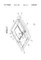
- FIG. 1 shows a drawing of a radio in accordance with the present invention.
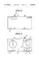
- FIG. 2 shows a drawing of a first surface of an antenna in accordance with the present invention.
- FIG. 3 shows a drawing of a second surface of an antenna in accordance with the present invention.
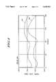
- FIG. 4 shows a graph of radiation patterns comparing a standard quarter-wavelength stub antenna to the antenna as described by the present invention.
- a radio 100 such as a CT-2 base station, is shown in FIG. 1 of the accompanying drawings.
- the base station 100 is comprised of a housing 101 which includes a controller board 116 covered by an outer perimeter controller shield 102.
- the controller shield 102 is attached to the controller board 116 by a series of ground (GND) clips 112 to provide a ground plane to the shield.
- the base station also includes a transceiver board 118 mated to the controller board 116 within the perimeter of the controller shield 102 through a multi-pin connector (not shown).
- the transceiver board 118 is covered by a radio frequency (RF) shield 104 having a series of GND clips 114 that mate the RF shield to the ground of the controller shield 102.
- RF radio frequency
- the compact CT-2 public base stations require two antennas 110 and 126, for the purpose of diversity, confined in a space of 3.5 inches (8.9 cm) by 7 inches (17.8 cm) located at the top of the metallic shields 102 and 104 within the housing 101. While the drawings show two substantially identical antennas, 110 and 126, disposed on a substrate 108, only one antenna 110 will be described by the invention.
- the transceiver board 118 includes two sets of substantially identical contacts, one set for antenna 110 and the other set for antenna 126. Only one set of contacts, the set for antenna 110, will be described by the invention.
- the set of contacts for antenna 110 includes three contact sockets (not shown) located on the transceiver board 118, one as an RF socket for transmitting or receiving an RF signal and the other two as mechanical sockets for providing a means of mechanical support to the substrate 108 connected to the top portion of the transceiver board.
- the RF socket provides an electrical contact between the transceiver board 118 and the antenna 110 contained within the substrate 108 for transmitting or receiving an RF signal.
- the substrate 108 includes corresponding antenna feed point 122 and mechanical feed points 124 to mate with the RF socket and mechanical sockets.
- the antenna feed point 122 and mechanical feed points 124 are antenna feed pin 122 and mechanical feed pins 124 respectively.
- Antenna feed pin 122 mates to the RF socket forming an electrical contact between the transceiver board 118 and the antenna 110 while mechanical feed pins 124 mate to the mechanical sockets to maintain the mechanical support for the substrate 108 once connected to the transceiver board 118.
- the antenna feed pin 122 is a low impedance point of approximately 50 ohms when mated to the transceiver board 118 at the RF socket.
- the impedance of antenna 110 is affected by surrounding metallic objects so matching of the antenna is typically done with the antenna located at the top end of the shields 102 and 104.
- the antenna 110 is located within non-conductive substrate 108 having two opposing surfaces. By printing traces of a conductive material, such as copper or gold, onto the substrate 108, the antenna 110 is formed.
- the substrate 108 in the preferred embodiment, comprises a printed circuit board of fire retarding glass epoxy material (FR4) having dielectric constant 4.7 and thickness of 31 mils (0.79 mm).
- the antenna 110 includes a feed section for providing the RF signal.
- the feed section comprises the antenna feed pin 122, located on the first surface of substrate 108, a quarter-wave feed section 202 and a coupling section 206, both located on the second surface of the substrate.
- the substrate 108 contains antenna feed pin 122 for coupling to the RF socket, located within transceiver board 118, and also for coupling to the first end of the quarter-wave feed 202.
- the quarter-wave feed 202 is formed from a meandered trace of 70 mils (1.78 mm) width and 3650 mils (9.27 cm) length that starts at antenna feed pin 122 and converts the low impedance point located at antenna feed pin 122 to a first high impedance region 203 along the top section of the trace 202.
- the first high impedance region 203 is then capacitively coupled through the board 108 to coupling section 206 on the opposing side of the board.
- the first high impedance region 203 is substantially in register with the coupling section 206. In the preferred embodiment, this capacitive coupling is achieved by locating the high impedance region 203 of the quarter-wave feed 202 directly underneath the coupling section 206 on the opposite side of the board 108.
- the coupling section 206 is fed into-an isolator means, which in the preferred embodiment comprises a substantially circular loop. 208, having a perimeter of approximately half a Wavelength and located on the second surface of the substrate 108.
- the circular loop 208 includes a first feed point 210 coupled to the coupling section 206, and a second feed point 212.
- the first feed point 210 and second feed point 212 are displaced approximately 180° opposite from each other within the circular loop 208.
- a quarter-wavelength radiator 214 located on the second surface of substrate 108 and coupled to the second feed point 212, provides a second high impedance region.
- the quarter-wavelength radiator 214 includes two sections, a vertical section 215 coupled to the second feed point 212 of the circular loop 208, and a horizontal top section 217 coupled to the vertical section.
- the quarter-wavelength radiator 214 is top loaded and provides an equivalent electrical distance of one quarter-wavelength.
- the circular loop 208 provides isolation between the first feed point 210 and the second feed point 212 thereby providing a reduction in the effects of the electric fields generated by the metallic shields 102 and 104 on the second high impedance region.
- the Circular loop 208 isolates, physically and electrically, the quarter-wavelength radiator 214 from shields 102, 104 and minimizes the distortion caused by the shields. Tuning of the antenna operating frequency is accomplished by selecting the appropriate length of the quarter-wavelength radiator 214.
- Antenna 110 uses quarter-wavelength radiator 214 to either transmit or receive an RF signal.
- a tuning stub 216 extending from the first feed point 210 of the circular loop.
- the tuning stub 216 is used to fine-tune the impedance of the antenna 110 by selecting the appropriate length.
- the antenna 110 described by the invention is tuned for 866 mega-hertz (MHz) and has a bandwidth of approximately 60 MHz with a minimum return loss of 10 dB across the band.
- the antenna 110 is formed by disposing the different sections of the antenna (antenna feed point 122, quarter-wave feed 202, coupling section 206, isolator means 208, tuning stub 216, and quarter-wavelength radiator 214) onto the substrate 108 as printed traces.
- the substrate material and layout of the printed circuit board used for manufacturing the antenna 110 is more easily manufactured than a coil style antenna that would comprise more mechanical parts. Repeatability of measurement is ensured by the inherent characteristics of the substrate material and the tolerance of the width of the traces.
- the antenna 110 transmits an average power approximately equal to that of a half-wavelength reference dipole antenna mounted to the same contact sockets, located on transceiver board 118, however the half-wavelength reference dipole antenna does not fit within housing 101.
- FIG. 4 A graph comparing the radiation pattern of a standard quarter-wavelength stub antenna that fits inside the housing 101 and the antenna as described by the invention is shown in FIG. 4.
- the pattern 402 represents the matched quarter-wavelength stub antenna and pattern 404 represents the antenna 110.
- the patterns measured over 360° in azimuth show the quarter-wavelength stub having peaks and dips associated with having a high impedance point next to the shields.
- the antenna 110 with pattern 404 provides a more consistent pattern with less variation in the signal level as well as an overall increase in radiated power of approximately 4.4 dB.
- the invention could be applied in other fashions to achieve similar results.
- the capacitive coupling could be accomplished on one surface of the substrate 108 by running the feed section and the coupling section side by side and in parallel rather than on opposing surfaces.
- the isolator means 208 could be formed by an elliptical radiator, such as an oval radiator, in order to achieve the half wavelength transfer.
- Other substrate materials could be used other than FR4 with trace width and board thickness adjusted for the dielectric constant of the material. If fine tuning of the impedance is not required the tuning stub 216 could be eliminated.
- a variety of different meandered line configurations could be employed to achieve the quarter-wave for the feed section and the quarter-wave radiator to accommodate various shapes and sizes of substrates.
- the antenna 110 as described by the invention has proven to be an effective means of providing an antenna which exhibits reduced radiation effects from shields held in close proximity to the antenna.
- This antenna 110 is easy to manufacture and excellent results can be obtained using inexpensive substrate materials.
Landscapes
- Engineering & Computer Science (AREA)
- Computer Networks & Wireless Communication (AREA)
- Details Of Aerials (AREA)
Abstract
Description
Claims (12)
Priority Applications (2)
| Application Number | Priority Date | Filing Date | Title |
|---|---|---|---|
| US08/192,529 US5428362A (en) | 1994-02-07 | 1994-02-07 | Substrate integrated antenna |
| EP95101034A EP0666610A1 (en) | 1994-02-07 | 1995-01-26 | Substrate integrated antenna |
Applications Claiming Priority (1)
| Application Number | Priority Date | Filing Date | Title |
|---|---|---|---|
| US08/192,529 US5428362A (en) | 1994-02-07 | 1994-02-07 | Substrate integrated antenna |
Publications (1)
| Publication Number | Publication Date |
|---|---|
| US5428362A true US5428362A (en) | 1995-06-27 |
Family
ID=22710055
Family Applications (1)
| Application Number | Title | Priority Date | Filing Date |
|---|---|---|---|
| US08/192,529 Expired - Lifetime US5428362A (en) | 1994-02-07 | 1994-02-07 | Substrate integrated antenna |
Country Status (2)
| Country | Link |
|---|---|
| US (1) | US5428362A (en) |
| EP (1) | EP0666610A1 (en) |
Cited By (6)
| Publication number | Priority date | Publication date | Assignee | Title |
|---|---|---|---|---|
| US5585806A (en) * | 1993-12-28 | 1996-12-17 | Mitsumi Electric Co., Ltd. | Flat antenna apparatus having a shielded circuit board |
| US5874920A (en) * | 1996-01-26 | 1999-02-23 | Fujitsu Limited | Portable radio equipment, and built-in antenna mounting structure and shielding structure for the portable radio equipment |
| US6204825B1 (en) * | 1997-04-10 | 2001-03-20 | Intermec Ip Corp. | Hybrid printed circuit board shield and antenna |
| US6326920B1 (en) | 2000-03-09 | 2001-12-04 | Avaya Technology Corp. | Sheet-metal antenna |
| US20040125039A1 (en) * | 2001-04-11 | 2004-07-01 | Hideki Sasaki | Data processing terminal, terminal designing device and method, computer program, and information storing medium |
| USD492671S1 (en) | 2003-03-26 | 2004-07-06 | Mitsumi Electric Co., Ltd. | Antenna |
Families Citing this family (1)
| Publication number | Priority date | Publication date | Assignee | Title |
|---|---|---|---|---|
| US10608330B2 (en) * | 2017-11-14 | 2020-03-31 | Gm Global Technology Operations, Llc | Method and apparatus to conceal near transparent conductors |
Citations (6)
| Publication number | Priority date | Publication date | Assignee | Title |
|---|---|---|---|---|
| JPS56134804A (en) * | 1980-03-25 | 1981-10-21 | Mitsubishi Electric Corp | Tracking antenna |
| JPS59169207A (en) * | 1983-03-16 | 1984-09-25 | Mitsubishi Electric Corp | Antenna feeding circuit |
| EP0246026A2 (en) * | 1986-05-09 | 1987-11-19 | Uniden Corporation | Antenna for wireless communication equipment |
| US4847626A (en) * | 1987-07-01 | 1989-07-11 | Motorola, Inc. | Microstrip balun-antenna |
| JPH039602A (en) * | 1989-06-06 | 1991-01-17 | C S R:Kk | Microwave receiver |
| US5349364A (en) * | 1992-06-26 | 1994-09-20 | Acvo Corporation | Electromagnetic power distribution system comprising distinct type couplers |
Family Cites Families (2)
| Publication number | Priority date | Publication date | Assignee | Title |
|---|---|---|---|---|
| FR2559623B1 (en) * | 1984-02-10 | 1986-06-20 | Malcombe Jean Claude | TRANSMISSION ANTENNA AND MINIATURE OMNIDIRECTIONAL GAIN |
| EP0186455A3 (en) * | 1984-12-20 | 1987-11-25 | The Marconi Company Limited | A dipole array |
-
1994
- 1994-02-07 US US08/192,529 patent/US5428362A/en not_active Expired - Lifetime
-
1995
- 1995-01-26 EP EP95101034A patent/EP0666610A1/en not_active Withdrawn
Patent Citations (6)
| Publication number | Priority date | Publication date | Assignee | Title |
|---|---|---|---|---|
| JPS56134804A (en) * | 1980-03-25 | 1981-10-21 | Mitsubishi Electric Corp | Tracking antenna |
| JPS59169207A (en) * | 1983-03-16 | 1984-09-25 | Mitsubishi Electric Corp | Antenna feeding circuit |
| EP0246026A2 (en) * | 1986-05-09 | 1987-11-19 | Uniden Corporation | Antenna for wireless communication equipment |
| US4847626A (en) * | 1987-07-01 | 1989-07-11 | Motorola, Inc. | Microstrip balun-antenna |
| JPH039602A (en) * | 1989-06-06 | 1991-01-17 | C S R:Kk | Microwave receiver |
| US5349364A (en) * | 1992-06-26 | 1994-09-20 | Acvo Corporation | Electromagnetic power distribution system comprising distinct type couplers |
Cited By (7)
| Publication number | Priority date | Publication date | Assignee | Title |
|---|---|---|---|---|
| US5585806A (en) * | 1993-12-28 | 1996-12-17 | Mitsumi Electric Co., Ltd. | Flat antenna apparatus having a shielded circuit board |
| US5874920A (en) * | 1996-01-26 | 1999-02-23 | Fujitsu Limited | Portable radio equipment, and built-in antenna mounting structure and shielding structure for the portable radio equipment |
| US6204825B1 (en) * | 1997-04-10 | 2001-03-20 | Intermec Ip Corp. | Hybrid printed circuit board shield and antenna |
| US6326920B1 (en) | 2000-03-09 | 2001-12-04 | Avaya Technology Corp. | Sheet-metal antenna |
| US20040125039A1 (en) * | 2001-04-11 | 2004-07-01 | Hideki Sasaki | Data processing terminal, terminal designing device and method, computer program, and information storing medium |
| US7002529B2 (en) * | 2001-04-11 | 2006-02-21 | Nec Corporation | Data processing terminal, terminal designing apparatus and method, computer program, and information storing medium |
| USD492671S1 (en) | 2003-03-26 | 2004-07-06 | Mitsumi Electric Co., Ltd. | Antenna |
Also Published As
| Publication number | Publication date |
|---|---|
| EP0666610A1 (en) | 1995-08-09 |
Similar Documents
| Publication | Publication Date | Title |
|---|---|---|
| US5451966A (en) | Ultra-high frequency, slot coupled, low-cost antenna system | |
| EP0637094B1 (en) | Antenna for mobile communication | |
| US6603430B1 (en) | Handheld wireless communication devices with antenna having parasitic element | |
| US6801169B1 (en) | Multi-band printed monopole antenna | |
| US6424300B1 (en) | Notch antennas and wireless communicators incorporating same | |
| US6404394B1 (en) | Dual polarization slot antenna assembly | |
| EP1079463B1 (en) | Asymmetric dipole antenna assembly | |
| CA2617756C (en) | Printed circuit notch antenna | |
| KR100638726B1 (en) | Antenna module and electronic device having same | |
| US20050035919A1 (en) | Multi-band printed dipole antenna | |
| US6348894B1 (en) | Radio frequency antenna | |
| US20040104849A1 (en) | Dual band antenna | |
| US5914695A (en) | Omnidirectional dipole antenna | |
| JP2001339226A (en) | Antenna system | |
| KR20000010756A (en) | Antenna device having a matching means | |
| US20040046697A1 (en) | Dual band antenna | |
| US5428362A (en) | Substrate integrated antenna | |
| JPH11340726A (en) | Antenna device | |
| JP4125118B2 (en) | Wideband built-in antenna | |
| US12107352B2 (en) | Antenna for sending and/or receiving electromagnetic signals | |
| EP0929116B1 (en) | Antenna device | |
| CN118712716B (en) | An electronic device | |
| US7598912B2 (en) | Planar antenna structure | |
| US6323812B1 (en) | Secondary antenna ground element | |
| KR100416885B1 (en) | Small antenna of wireless data communication |
Legal Events
| Date | Code | Title | Description |
|---|---|---|---|
| AS | Assignment |
Owner name: MOTOROLA, INC. A CORP. OF DELAWARE, ILLINOIS Free format text: ASSIGNMENT OF ASSIGNORS INTEREST;ASSIGNORS:CHATZIPETROS, ARGYRIOS;MARKO, PAUL;KRAYESKI, PAUL;REEL/FRAME:006881/0640 Effective date: 19940127 |
|
| STCF | Information on status: patent grant |
Free format text: PATENTED CASE |
|
| FPAY | Fee payment |
Year of fee payment: 4 |
|
| FPAY | Fee payment |
Year of fee payment: 8 |
|
| FPAY | Fee payment |
Year of fee payment: 12 |
|
| AS | Assignment |
Owner name: MOTOROLA MOBILITY, INC, ILLINOIS Free format text: ASSIGNMENT OF ASSIGNORS INTEREST;ASSIGNOR:MOTOROLA, INC;REEL/FRAME:025673/0558 Effective date: 20100731 |
|
| AS | Assignment |
Owner name: WI-LAN INC., CANADA Free format text: ASSIGNMENT OF ASSIGNORS INTEREST;ASSIGNOR:MOTOROLA MOBILITY, INC.;REEL/FRAME:026916/0718 Effective date: 20110127 |
|
| AS | Assignment |
Owner name: QUARTERHILL INC., CANADA Free format text: MERGER AND CHANGE OF NAME;ASSIGNORS:WI-LAN INC.;QUARTERHILL INC.;REEL/FRAME:042902/0932 Effective date: 20170601 |
|
| AS | Assignment |
Owner name: WI-LAN INC., CANADA Free format text: ASSIGNMENT OF ASSIGNORS INTEREST;ASSIGNOR:QUARTERHILL INC.;REEL/FRAME:043167/0233 Effective date: 20170601 |