US5421570A - Cartridge for feeding oversized paper stock from a standard size tray - Google Patents
Cartridge for feeding oversized paper stock from a standard size tray Download PDFInfo
- Publication number
- US5421570A US5421570A US08/010,205 US1020593A US5421570A US 5421570 A US5421570 A US 5421570A US 1020593 A US1020593 A US 1020593A US 5421570 A US5421570 A US 5421570A
- Authority
- US
- United States
- Prior art keywords
- stack
- cartridge
- improvement
- sheet stock
- tray
- Prior art date
- Legal status (The legal status is an assumption and is not a legal conclusion. Google has not performed a legal analysis and makes no representation as to the accuracy of the status listed.)
- Expired - Fee Related
Links
- 230000007246 mechanism Effects 0.000 claims description 12
- 238000012986 modification Methods 0.000 description 3
- 230000004048 modification Effects 0.000 description 3
- 238000005452 bending Methods 0.000 description 1
- 238000010276 construction Methods 0.000 description 1
- 230000007423 decrease Effects 0.000 description 1
- 230000002708 enhancing effect Effects 0.000 description 1
- 238000003780 insertion Methods 0.000 description 1
- 230000037431 insertion Effects 0.000 description 1
- 238000005192 partition Methods 0.000 description 1
Images


Classifications
-
- B—PERFORMING OPERATIONS; TRANSPORTING
- B65—CONVEYING; PACKING; STORING; HANDLING THIN OR FILAMENTARY MATERIAL
- B65H—HANDLING THIN OR FILAMENTARY MATERIAL, e.g. SHEETS, WEBS, CABLES
- B65H1/00—Supports or magazines for piles from which articles are to be separated
Definitions
- This invention relates to a cartridge inserted into a printer or copier paper tray.
- the invention relates to a cartridge which is placeable into a standard sized paper stock feeding tray which will allow the use of oversized paper stock in the standard sized tray.
- the invention more particularly relates to a cartridge which folds the oversized paper stock to allow its insertion into a standard sized paper tray.
- printers and copiers in particular, but not exclusively xerographic or like copiers, utilize more than one paper stock to provide a variety of duplication functions.
- These printers and copiers may have one or more trays that can accommodate standard size stock (media).
- printers and/or copiers are often equipped with only one tray to accommodate oversized paper stock.
- the Xerox 5090 copy machine is designed with two standard size trays, but only one oversized paper tray.
- the operator must either run the job uncollated and reload the oversized tray at different points during the job or partition the job by stock characteristics, run in uncollated mode and collate off-line. Each of these operations is inefficient.
- a further object of this invention is to provide a new cartridge for feeding oversized paper stock which can be accommodated by a standard size paper feed tray.
- the cartridge of this invention comprises a housing having an outlet opening which can be positioned in alignment with the discharge opening of a paper feeding tray.
- the cartridge is formed such that a stack of sheet stock is positioned with one edge located at or passing through the outlet opening.
- the stack of sheet stock is folded upon itself and enclosed in the cartridge housing.
- a means is provided in the housing for maintaining the sheet stock in an aligned and folded position while allowing removal of successive sheets from the sheet stock through the housing outlet and subsequently the discharge opening.
- the cartridge assembly will hold the sheet stock in a C or S-shaped pattern. More preferably, the cartridge assembly will hold the sheet stock in a J-shaped pattern.
- the cartridge assembly include an internal guide for maintaining the stack of sheet stock in a folded and aligned position. More preferably, the internal guide is comprised of a roller about which the stack of sheet stock is folded, allowing ease of movement when individual sheets are removed from the cartridge assembly.
- FIG. 1 is a perspective view of a S-shaped cartridge.
- FIG. 2 is a perspective view of a C-shaped cartridge.
- FIG. 3 is a perspective view of a J-shaped cartridge.
- FIG. 4 is a perspective view of the J-shaped cartridge in an opened loading position.
- FIG. 5 is a perspective view of the J-shaped cartridge loaded with paper prior to closing.
- FIG. 6 is a side plan view of a cartridge which reduces the feedstock length by bending.
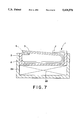
- FIG. 7 shows a tray and an elevator mechanism moving the cartridge.
- the cartridge 1 is designed to position a stack of printer or copier stock paper 5 in the feeder tray (not shown) of a printer or copier. It is also apparent that the cartridge 1 facilitates the use of oversized sheets of paper, such as 11" ⁇ 17" sheets, in a standard sized tray. As utilized herein, standard size generally refers to 81/2" ⁇ 11", 9" ⁇ 11", 81/2" ⁇ 14", and A4 sized paper. Oversized stock generally refers to "11 ⁇ 17" or A3 sizes. It should be understood that the invention is not limited to these specific paper sizes, in that, it applies to the use of copier or printer paper stock larger than that which can be accommodated by the copier or printer feeder tray. It should also be understood that as utilized herein, length of sheet stock generally refers to the axis of the paper parallel to the machine feed direction. This definition is exemplified in FIG. 5 by "l" which lies parallel to the feed direction.
- FIGS. 1 and 2 demonstrate a cartridge housing 2 including an outlet 3 sufficient for passage of sheet stock 5 therethrough.
- outlet 3 will locate the paper stock 5 on ledge 6 which can be aligned with the discharge opening of the tray to make the sheet stock 5 available to the printer or copier sheet feeding mechanism.
- the preferably flat ledge 6 provides easy access to a printer or copier sheet feeding mechanism.
- a tray and sheet feeding mechanism for which cartridge 1 is adaptable is exemplified in U.S. Pat. Nos. 4,589,647; 4,699,369 and 5,079,723 incorporated herein by reference.
- sheet stock 5 is held in cartridge housing 2 in a folded alignment.
- this alignment is achieved by the shape of the cartridge housing 2 in combination with prongs 7.
- Prongs 7 maintain the sheet stock 5 within cartridge 1 in an aligned and folded position.
- Prongs 7 are also positioned to allow removal of successive sheets when engaged by the printer or copier sheet feeding mechanism while maintaining alignment of the stack generally.
- Prongs 7 are positioned to hold down the feed edge 9 and keep the remaining sheets 5 from uncurling into the printer or copier equipment.
- prongs 7 are low friction or spring loaded at the tips.
- the tip may be a roller, a ratcheted roller, a low friction pad or a curved surface. It should be noted that the terminal end of prongs 7 in contact with the sheet stock 5 are rounded.
- a fold generally means at least a partial overlap of at least one sheet by a related portion of the same sheet. It is not necessary that this overlap lead to physical contact of the sheet upon itself as can be seen by the gap or gaps between the layers of paper in FIGS. 1 and 2. Alternatively, the fold may be a roll.
- the required level of folding must be sufficient to enable the sheet stock and cartridge housing to fit within the available tray.
- the paper is curved. This is appropriate when the paper is not significantly longer than the paper tray. Accordingly, a slight bend or curve to the paper stock shortens the required tray length.
- the cartridge 21 includes a shaped or molded portion 22 which holds the paper stock 5 in a curved position. A stop means 23 is optional. Paper stock 5 is removed from cartridge 21 at lip 24.
- FIG. 3 demonstrates a cartridge 1 having a preferred cartridge housing 10 which forms a J-shaped paper stack 5.
- the J-shape of FIG. 3 represents an alternative style of cartridge feed, in that, paper exits cartridge 10 from the lower fold of sheet stock 5. This design eliminates friction created by the weight of the uppermost portions of paper stock 5 upon the sheet being withdrawn in the S- and C-shaped cartridges, wherein the weight of the paper upon itself may cause binding at the bend area during withdrawal.
- FIG. 3 also demonstrates a more elaborate prong mechanism 11 with end means 13.
- FIG. 3 also shows a preferred roller mechanism 15 for enhancing the folding of the sheets.
- roller 15 establishes a low coefficient of friction in sliding sheet stock 5 through cartridge 10 and insures that the trail edge of the sheet stock is kept from being pulled into the feeder mechanism prematurely, causing a misfeed.
- Roller 15 is attached to prongs 11 via angle bracket 17.
- FIG. 4 provides a view of the combined angle bracket 17 and roller 15.
- cartridge 10 includes upright member 12 located adjacent the roller, running generally axial thereto.
- Member 12 elevates sheet stock 5, maintaining alignment.
- Member 12 could be rounded if desired.
- member 12 could be a curved surface extending from wall 20 to the base of cartridge 10.
- Member 12 can contact the base anywhere between wall 20 and roller 15. Generally, the curve would be convex to support paper stock 5.
- Further preferred embodiments include adding a finger or tab (not shown) on the cartridge to activate the empty switch on the paper tray to indicate when the cartridge is empty. This is necessary because the presence of the cartridge will simulate a full tray.
- FIG. 2 demonstrates a beveled corner 8 within cartridge housing 2.
- the beveled corner offsets a first edge 14 of sheet stock 5.
- the feed edge 9, opposite the end abutting the corner, is thereby adjusted for the longer curvature path traveled by the outside of sheet stock 5. This functions to keep feed edge 9 aligned.
- the loading of a cartridge is particular for each design.
- the J-cartridge of FIG. 3 would be opened as shown in FIG. 4.
- Prongs 11 and roller 15 tilt by hinges shown generally at 19 to open the cartridge and allow paper 5 to be laid flat into open cartridge 10 as shown in FIG. 5.
- paper stock 5 is supported by prongs 11 and flat ledge 6.
- the paper will be folded into the position shown in FIG. 3.
- FIGS. 1 and 2 can also be provided with a opening means to allow easy access for paper loading within the cartridge.
- the cartridge of the current invention is effective in storing sheet stock paper for feed via a tray to a printer or copier.
- This invention is particularly effective for oversized feed.
- the cartridge significantly decreases the length of the sheet and accordingly the required length of the tray.
- the cartridge of this invention provides a low cost alternative to adding a second oversized paper stock tray.
Abstract
Description
Claims (21)
Priority Applications (4)
| Application Number | Priority Date | Filing Date | Title |
|---|---|---|---|
| US08/010,205 US5421570A (en) | 1993-01-28 | 1993-01-28 | Cartridge for feeding oversized paper stock from a standard size tray |
| EP94300344A EP0609002B1 (en) | 1993-01-28 | 1994-01-18 | Cartridge for feeding oversized paper stock from a standard size tray |
| DE69407315T DE69407315T2 (en) | 1993-01-28 | 1994-01-18 | Enclosure for pulling an oversized sheet from a stack from a standard output bin |
| JP00490094A JP3436318B2 (en) | 1993-01-28 | 1994-01-21 | Cartridge for feeding extra-large paper from standard size tray |
Applications Claiming Priority (1)
| Application Number | Priority Date | Filing Date | Title |
|---|---|---|---|
| US08/010,205 US5421570A (en) | 1993-01-28 | 1993-01-28 | Cartridge for feeding oversized paper stock from a standard size tray |
Publications (1)
| Publication Number | Publication Date |
|---|---|
| US5421570A true US5421570A (en) | 1995-06-06 |
Family
ID=21744491
Family Applications (1)
| Application Number | Title | Priority Date | Filing Date |
|---|---|---|---|
| US08/010,205 Expired - Fee Related US5421570A (en) | 1993-01-28 | 1993-01-28 | Cartridge for feeding oversized paper stock from a standard size tray |
Country Status (4)
| Country | Link |
|---|---|
| US (1) | US5421570A (en) |
| EP (1) | EP0609002B1 (en) |
| JP (1) | JP3436318B2 (en) |
| DE (1) | DE69407315T2 (en) |
Cited By (6)
| Publication number | Priority date | Publication date | Assignee | Title |
|---|---|---|---|---|
| US5967680A (en) * | 1998-01-20 | 1999-10-19 | Eastman Kodak Company | Compact printer with curved supply tray |
| US20060232000A1 (en) * | 2005-04-15 | 2006-10-19 | Toshiaki Takahashi | Method and apparatus for image forming capable of effectively supporting a recording medium |
| US20070040317A1 (en) * | 2005-08-18 | 2007-02-22 | Bakker Johan P | Low-profile document feeding machine with hopper extension |
| US20070040318A1 (en) * | 2005-08-18 | 2007-02-22 | Bakker Johan P | Low-profile document feeding machine with hopper floor for column forming documents |
| US20090080957A1 (en) * | 2007-09-26 | 2009-03-26 | Oki Data Corporation | Medium holding apparatus and image forming apparatus that employs the medium holding apparatus |
| US7641190B2 (en) * | 2002-07-12 | 2010-01-05 | Oki Data Corporation | Medium tray and image recording apparatus using the same |
Families Citing this family (1)
| Publication number | Priority date | Publication date | Assignee | Title |
|---|---|---|---|---|
| NL1017652C2 (en) * | 2001-03-20 | 2002-09-23 | Ocu Technologies B V | Method for packaging a collection of image-receiving material and a collection of image-receiving material enclosed by a holder. |
Citations (3)
| Publication number | Priority date | Publication date | Assignee | Title |
|---|---|---|---|---|
| JPS61254430A (en) * | 1985-05-04 | 1986-11-12 | Top Jimuki Kk | Copying sheet accommodating method in sheet feed cassette and sheet feed cassette thereof |
| JPH0336122A (en) * | 1989-07-03 | 1991-02-15 | Fuji Photo Film Co Ltd | Paper feeding cassette and jig |
| US5145163A (en) * | 1989-11-24 | 1992-09-08 | Medrad, Inc. | Film sheet load magazine |
Family Cites Families (3)
| Publication number | Priority date | Publication date | Assignee | Title |
|---|---|---|---|---|
| DE2807354A1 (en) * | 1978-02-21 | 1979-08-23 | Nuenninghoff Heinrich | Paper sheet storage container - is spiral-shaped with stop at right angles to inner end of spiral |
| US5172903A (en) * | 1990-09-28 | 1992-12-22 | Konica Corporation | Paper feed cassette |
| GB9300806D0 (en) * | 1993-01-16 | 1993-03-10 | Keegan Roger N | Print tray adaptor |
-
1993
- 1993-01-28 US US08/010,205 patent/US5421570A/en not_active Expired - Fee Related
-
1994
- 1994-01-18 DE DE69407315T patent/DE69407315T2/en not_active Expired - Fee Related
- 1994-01-18 EP EP94300344A patent/EP0609002B1/en not_active Expired - Lifetime
- 1994-01-21 JP JP00490094A patent/JP3436318B2/en not_active Expired - Fee Related
Patent Citations (3)
| Publication number | Priority date | Publication date | Assignee | Title |
|---|---|---|---|---|
| JPS61254430A (en) * | 1985-05-04 | 1986-11-12 | Top Jimuki Kk | Copying sheet accommodating method in sheet feed cassette and sheet feed cassette thereof |
| JPH0336122A (en) * | 1989-07-03 | 1991-02-15 | Fuji Photo Film Co Ltd | Paper feeding cassette and jig |
| US5145163A (en) * | 1989-11-24 | 1992-09-08 | Medrad, Inc. | Film sheet load magazine |
Cited By (9)
| Publication number | Priority date | Publication date | Assignee | Title |
|---|---|---|---|---|
| US5967680A (en) * | 1998-01-20 | 1999-10-19 | Eastman Kodak Company | Compact printer with curved supply tray |
| US7641190B2 (en) * | 2002-07-12 | 2010-01-05 | Oki Data Corporation | Medium tray and image recording apparatus using the same |
| US20060232000A1 (en) * | 2005-04-15 | 2006-10-19 | Toshiaki Takahashi | Method and apparatus for image forming capable of effectively supporting a recording medium |
| US20070040317A1 (en) * | 2005-08-18 | 2007-02-22 | Bakker Johan P | Low-profile document feeding machine with hopper extension |
| US20070040318A1 (en) * | 2005-08-18 | 2007-02-22 | Bakker Johan P | Low-profile document feeding machine with hopper floor for column forming documents |
| US7887047B2 (en) * | 2005-08-18 | 2011-02-15 | Burroughs Payment Systems, Inc. | Low-profile document feeding machine with hopper floor for column forming documents |
| US7887046B2 (en) * | 2005-08-18 | 2011-02-15 | Burroughs Payment Systems, Inc. | Low-profile document feeding machine with hopper extension |
| US20090080957A1 (en) * | 2007-09-26 | 2009-03-26 | Oki Data Corporation | Medium holding apparatus and image forming apparatus that employs the medium holding apparatus |
| US8401456B2 (en) * | 2007-09-26 | 2013-03-19 | Oki Data Corporation | Medium holding apparatus and image forming apparatus that employs the medium holding apparatus |
Also Published As
| Publication number | Publication date |
|---|---|
| DE69407315T2 (en) | 1998-07-16 |
| DE69407315D1 (en) | 1998-01-29 |
| EP0609002B1 (en) | 1997-12-17 |
| JPH06271089A (en) | 1994-09-27 |
| EP0609002A2 (en) | 1994-08-03 |
| EP0609002A3 (en) | 1995-03-01 |
| JP3436318B2 (en) | 2003-08-11 |
Similar Documents
| Publication | Publication Date | Title |
|---|---|---|
| US4946152A (en) | Sorter-finisher | |
| US5321479A (en) | Electrophotographic apparatus | |
| US8020857B2 (en) | Paper sheet processing apparatus, and paper sheet processing method | |
| US5826158A (en) | Finisher and method of stapling by using the same | |
| JPH0885663A (en) | Inverting and stacking system for sheet | |
| JPS59190128A (en) | Paper feed device of copying machine and paper feed cassette used for copying machine | |
| US5421570A (en) | Cartridge for feeding oversized paper stock from a standard size tray | |
| US4579328A (en) | Copy paper feeding device for electrophotographic copying machine | |
| US5456456A (en) | Paper feeding device having paper inverting means | |
| US4886259A (en) | Sorter-finisher system | |
| US6328298B1 (en) | Image forming apparatus and finisher therefor | |
| JPS61254430A (en) | Copying sheet accommodating method in sheet feed cassette and sheet feed cassette thereof | |
| EP0441562A1 (en) | Sheet delivering mechanism | |
| JP2001072303A (en) | Sheet loading device and image forming device | |
| JPH054727A (en) | Sheet loading device | |
| US5452072A (en) | Transfer unit mounted on a pivotal upper cover | |
| US5317365A (en) | Supply hopper for fanfold paper stacks | |
| JP2000318845A (en) | Cassette tray, and image forming device | |
| JP3521039B2 (en) | Paper feed mechanism | |
| JP4756751B2 (en) | Sheet stacking apparatus, sheet post-processing apparatus and image forming apparatus provided with the apparatus | |
| JPH023184B2 (en) | ||
| JP3452631B2 (en) | Sheet storage device for image forming apparatus | |
| JPS6312107Y2 (en) | ||
| JPH09309626A (en) | Sheet feeding tray of image forming device | |
| JPH01251045A (en) | Electrophotographic copying machine |
Legal Events
| Date | Code | Title | Description |
|---|---|---|---|
| AS | Assignment |
Owner name: XEROX CORPORATION, CONNECTICUT Free format text: ASSIGNMENT OF ASSIGNORS INTEREST.;ASSIGNORS:HUBE, RANDALL R.;FARRELL, MICHAEL E.;REEL/FRAME:006421/0626 Effective date: 19930125 |
|
| FPAY | Fee payment |
Year of fee payment: 4 |
|
| FEPP | Fee payment procedure |
Free format text: PAYOR NUMBER ASSIGNED (ORIGINAL EVENT CODE: ASPN); ENTITY STATUS OF PATENT OWNER: LARGE ENTITY |
|
| AS | Assignment |
Owner name: BANK ONE, NA, AS ADMINISTRATIVE AGENT, ILLINOIS Free format text: SECURITY INTEREST;ASSIGNOR:XEROX CORPORATION;REEL/FRAME:013153/0001 Effective date: 20020621 |
|
| FPAY | Fee payment |
Year of fee payment: 8 |
|
| AS | Assignment |
Owner name: JPMORGAN CHASE BANK, AS COLLATERAL AGENT, TEXAS Free format text: SECURITY AGREEMENT;ASSIGNOR:XEROX CORPORATION;REEL/FRAME:015134/0476 Effective date: 20030625 Owner name: JPMORGAN CHASE BANK, AS COLLATERAL AGENT,TEXAS Free format text: SECURITY AGREEMENT;ASSIGNOR:XEROX CORPORATION;REEL/FRAME:015134/0476 Effective date: 20030625 |
|
| REMI | Maintenance fee reminder mailed | ||
| LAPS | Lapse for failure to pay maintenance fees | ||
| STCH | Information on status: patent discontinuation |
Free format text: PATENT EXPIRED DUE TO NONPAYMENT OF MAINTENANCE FEES UNDER 37 CFR 1.362 |
|
| FP | Lapsed due to failure to pay maintenance fee |
Effective date: 20070606 |
|
| AS | Assignment |
Owner name: XEROX CORPORATION, CONNECTICUT Free format text: RELEASE BY SECURED PARTY;ASSIGNOR:JPMORGAN CHASE BANK, N.A. AS SUCCESSOR-IN-INTEREST ADMINISTRATIVE AGENT AND COLLATERAL AGENT TO JPMORGAN CHASE BANK;REEL/FRAME:066728/0193 Effective date: 20220822 |