US542004A - nordberg - Google Patents
nordberg Download PDFInfo
- Publication number
- US542004A US542004A US542004DA US542004A US 542004 A US542004 A US 542004A US 542004D A US542004D A US 542004DA US 542004 A US542004 A US 542004A
- Authority
- US
- United States
- Prior art keywords
- chamber
- water
- steam
- tubes
- heater
- Prior art date
- Legal status (The legal status is an assumption and is not a legal conclusion. Google has not performed a legal analysis and makes no representation as to the accuracy of the status listed.)
- Expired - Lifetime
Links
- XLYOFNOQVPJJNP-UHFFFAOYSA-N water Substances O XLYOFNOQVPJJNP-UHFFFAOYSA-N 0.000 description 34
- 238000005192 partition Methods 0.000 description 7
- 239000012535 impurity Substances 0.000 description 5
- 241000239290 Araneae Species 0.000 description 2
- 239000013049 sediment Substances 0.000 description 2
- 229910001369 Brass Inorganic materials 0.000 description 1
- RYGMFSIKBFXOCR-UHFFFAOYSA-N Copper Chemical compound [Cu] RYGMFSIKBFXOCR-UHFFFAOYSA-N 0.000 description 1
- 239000010951 brass Substances 0.000 description 1
- 230000005494 condensation Effects 0.000 description 1
- 238000009833 condensation Methods 0.000 description 1
- 239000004020 conductor Substances 0.000 description 1
- 238000010276 construction Methods 0.000 description 1
- 239000010949 copper Substances 0.000 description 1
- 229910052802 copper Inorganic materials 0.000 description 1
- 238000010168 coupling process Methods 0.000 description 1
- 238000005859 coupling reaction Methods 0.000 description 1
- 238000007689 inspection Methods 0.000 description 1
- 230000008439 repair process Effects 0.000 description 1
- 230000000630 rising effect Effects 0.000 description 1
Images

Classifications
-
- F—MECHANICAL ENGINEERING; LIGHTING; HEATING; WEAPONS; BLASTING
- F28—HEAT EXCHANGE IN GENERAL
- F28F—DETAILS OF HEAT-EXCHANGE AND HEAT-TRANSFER APPARATUS, OF GENERAL APPLICATION
- F28F9/00—Casings; Header boxes; Auxiliary supports for elements; Auxiliary members within casings
- F28F9/001—Casings in the form of plate-like arrangements; Frames enclosing a heat exchange core
-
- Y—GENERAL TAGGING OF NEW TECHNOLOGICAL DEVELOPMENTS; GENERAL TAGGING OF CROSS-SECTIONAL TECHNOLOGIES SPANNING OVER SEVERAL SECTIONS OF THE IPC; TECHNICAL SUBJECTS COVERED BY FORMER USPC CROSS-REFERENCE ART COLLECTIONS [XRACs] AND DIGESTS
- Y10—TECHNICAL SUBJECTS COVERED BY FORMER USPC
- Y10S—TECHNICAL SUBJECTS COVERED BY FORMER USPC CROSS-REFERENCE ART COLLECTIONS [XRACs] AND DIGESTS
- Y10S165/00—Heat exchange
- Y10S165/051—Heat exchange having expansion and contraction relieving or absorbing means
- Y10S165/052—Heat exchange having expansion and contraction relieving or absorbing means for cylindrical heat exchanger
- Y10S165/053—Flexible or movable header or header element
- Y10S165/054—Movable header, e.g. floating header
- Y10S165/055—Movable header, e.g. floating header including guiding means for movable header
Definitions
- Return and outlet pipe E passing centrally through the tube D, is secured at its lower end by a nut e to the bottom a of the lower chamber A and at its upper end by a nut e to the upper tubehead.
- the upper end of said pipe E is elevated and held above the bottom of chamber B by a sleeve 6 and a spider e interposed between the nut e and the upper tube-head, the spider e affording free communication between said chamber and the tube D.
- the pipe E thus serves to bind the upper and lower heads together, and thereby counteracts the tendency of the steam to lift the upper head and loosen the joints between the tubes 0 and D and the upper and lower heads, in which they are secured.
- a branch pipe E connected by a T-coupling with the pipe E in the lower chamber A, passes horizontally out through the wall of said chamber to the boiler or other apparatus with which the heater is connected.
- Y 2 In a water heater, the combination of a hollow base provided with steam inlet and outlet connections, a hollow head, tubes connecting said head with the base, water supply and discharge connections passing through the base and communicating, one with the water chamber therein and the other with the chamber in said hollow head, and a steam jacket surrounding. said tubes, independent of all external steam and water connections of the heater, substantially as and for the purposes set forth.
- a base having a Water chamber and a steam space or belt around it with inlet and outlet connections, anupper head and chamber, tubes connecting said upper head and chamber with the chamber in the base, a jacket surrounding said tubes, and removable independently of all external connections of the heater and partitions in said steam belt and the space above it between the inlet and outlet steam connections, substantially as and for the purposes set forth.
- a base having an inner water chamber and a steam space around it, said steam space having inlet and outlet connections on opposite sides and intermediate partitions, an upper tube-head and chamber connected by tubes with the water chamber in the base, a supply pipe leading into the chamber in the base an outlet pipe leading from the upper part of the upper chamber out through the base, and a removable steam jacket surrounding said ICO tubes independent of all external steam and Water inlet and outlet connections of the heater substantially as and for the purposes set forth.
- a base having an inner Water chamber provided with a removable bottom and an annular steam belt around said chamber provided on opposite sides with inlet and outlet connections and intermediate partitions, an upper chamber connected by tubes with the chamber in the base and provided with a removable cover, a water supply or inlet pipe leadin g into the chamber in the base, a Water outlet pipe leading from the upper part of the upper chamber through the lower chamber and secured on the upper side of the upper tube head and on the under side of the bottom of the lower chamber and a branch pipe connected with said outlet pipe and leading laterally out through the base of the heater, substantially as and for the purposes set forth.
- a water heater the combination of the base having a chamber with a removable bottom, and a steam space or belt around said chamberprovided on opposite sides with inlet and outlet openings and with intermediate partitions, an upper chamber provided with a removable cover, tubes connecting said chambers, a pipe passing through the central tube and the lower'chamber and secured at its ends by nuts on the under side of the base and on the upper side of theupper tube head, a branch pipe connected with said pipe in the lower chamber and. leading laterally out through the base, a water inlet or supply pipe leading into the upper part of the chamber in the base, and a steam jacket inclosing said tubes and the upper chamber and detachably secured to the base independently of the steam and water connections therewith, substantially as and for the purposes set forth.
Landscapes
- Engineering & Computer Science (AREA)
- Physics & Mathematics (AREA)
- Thermal Sciences (AREA)
- Mechanical Engineering (AREA)
- General Engineering & Computer Science (AREA)
- Commercial Cooking Devices (AREA)
Description
(N0 Modl.) 2 sheets-sneer 1.
' B. V.'N'ORDBERG. FEED WATERIHBATER- No. 542,004. Patented July 2 1895.
(No Model.) I m RTNORDBERG. FEED WATER HEATER.
No. 542,004. Patented July 2, 1895.
:5 Sheets-Sheet 2.
Wifizeaaes: fwarpibzx Unwrap TATES PATENT Orrrcn.
BRUNO V. NORDBERG, OF MILWAUKEE, WISCONSIN, ASSIGNOR TO THE BRUNO NORDBERG COMPANY, OF SAMEPLACE. I
FEED-WATER HEATER.
SPECIFICATION forming part of Letters Patent No. 542,004, dated July 2, 1895..
Applicatio fil d August 23, 1892. Serial No. 443.339- No model.)
T0 00% whom it may concern.-
Be it known that I, BRUNO V. NORDBERG, of Milwaukee, in the county of Milwaukee and State of WVisconsin, haveinvented certain new and useful Improvements in Feed Water Heaters; and I do hereby declare that the following is a full, clear, and exact description of the invention, which will enable others skilled in the art to which it pertains to make and use the same, reference being had to the accompanying drawings, and to the letters of reference marked thereon,which form a part. of this specification.
The main objects of my invention are to provide for easy access to the interior of the heater and of the upper and lower tube-heads for the purpose of inspection, repairs, and removal of impurities without disturbing the connections of the heater; to counteract the lifting tendency of the steam on the upper head, and thus prevent straining and loosening the joints betweent-he tubes and the heads in which they are secured at the ends; to prevent back-pressure through the exhaust or steam inlet; to distribute the steam among the water-tubes, and thereby utilizeto the greatest possible extent the heat contained in the steam for raising the temperature of the water; to separate impurities from the water entering the heater and to facilitate their removal therefrom.
It consists of certain novel features in the construction and arrangement of parts hereinafter particularly described, and pointed out in the claims.
In the accompanying drawings like letters designate the same parts in the several figures.
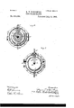
Figure l is a vertical medial section of my improved heater. Fig. 2 is a side elevation of the same, a section thereof being removed and a portion of the jacket or shell being broken away at its upper end. Fig. 3 is a vertical medial section of the base of the heater, taken in a plane at right angles to that of Fig. 1. Fig. at is a horizontal cross-section of the base on the line 4 4, Fig. 2; and Fig. 5 is a similar section on the line 5 5, Fig. 2.
A is the lower tube-head and chamber, which is formed with an annular belt or space at around its sides and with a removable bottom a and constitutes therewith the base of the heater. The outer walls of the annular steam belt or space a are formed on opposite sides with inlet and outlet exhaust or steam openings and pipe connections a and a B is the upper tube-head and chamber, which is formed with a removable cover Z) and connected by tubes 0 C and a larger central tube D (which are preferably made of brass or copper or some other good conductor of heat) with the lower head A. Return and outlet pipe E, passing centrally through the tube D, is secured at its lower end by a nut e to the bottom a of the lower chamber A and at its upper end by a nut e to the upper tubehead. The upper end of said pipe E is elevated and held above the bottom of chamber B by a sleeve 6 and a spider e interposed between the nut e and the upper tube-head, the spider e affording free communication between said chamber and the tube D. The pipe E thus serves to bind the upper and lower heads together, and thereby counteracts the tendency of the steam to lift the upper head and loosen the joints between the tubes 0 and D and the upper and lower heads, in which they are secured. A branch pipe E, connected by a T-coupling with the pipe E in the lower chamber A, passes horizontally out through the wall of said chamber to the boiler or other apparatus with which the heater is connected.
F is the water inlet or supply pipe, connected with the opposite side of chamber A, preferably near the top.
G is a drain-pipe provided with a suitable cook or valve (not shown) leading out of the lower portion of the annular steam space or belt a for the purpose of removing from time to time the water of condensation and sediment collecting therein. The bottom a of the lower chamber is provided with a handholeand cover a for the purpose of access to the interior of chamber A without removing the bottom a.
H is the shell or jacket of the heater, surrounding the upper head and tubes 0 O, and detachably secured to the base in the usual or any suitable manner. per end at the proper distance from the up per head B by studs or bolts 71. h, secured in and projecting radially from said head, as
It is held at the up-' ICO shown in Figs. 1 and 2. The annular steam belt or space a in the base is divided on opposite sides between the inlet and outlet openings a and a by partitions J J, and above these partitions thespace between the tubes 0 O and the jacket H is closed by partition-plates K K, extending upwardly to a point near the upper head 13. The steam entering the inlet-opening at on one side of the heater is thus compelled to pass upwardly and between the tubes before it can escape through the outlet-opening a on the opposite side of the heater.
My improved heater operates as follows: Water entering the upper portion of lower chamber A through pipe F (shown in Fig. 3) passes thence upwardly, as indicated by arrows, through the tubes 0 O and D into the upper chamber B, and, rising therein to the level of the upper end of pipe E, descends through said pipe and passes out of the heater through the branch E to the boiler or other apparatus to be supplied. Steam entering the annular belt a in the base through the inlet-openinga therein expands and fills said belt on that side of the heater, transmitting a portion of its heat to the walls of chamber A, which in turn transmit it to the water contained therein. The steam being prevented by the partitions J J from passing around said belt a to 'the outlet-opening a on the opposite side of the heater is compelled to risein the space between the tubes G and shell H, and, passing upwardly and between said tubes, gives 06 its heat, which is transmitted through the walls of the tubes to the water contained therein. The partition-plates K K compel the steam as it rises above chamber A to pass upwardly and across the heater between the tubes 0 O and D before it can escape through the outlet-opening a and thereby give off the greatest possible amount of heat which it contains to said tubes, to be transmitted thereby to the water passing through them. As the water enters the upper portion of chamberA the flow is checked and any impurities contained therein are allowed to settle to the bottom, from which they may be readily removed through the hand-hole a The water thus freed from a portion of the impurities contained therein passes from the upper portion of chamber A through tubes 0 O and D into the bottom of chamber B, where its flow is again retarded and remaining impurities are allowed to settle. From the upper part of chamber B the purer clarified portion of the water which has been heated by its passage through the tubes 0 and D exposed to the steam is drawn off through the base by the return and outlet pipe E E. While water is passing through the upper and lower chambers and the tubes connecting them the jacket H may pairs, and the removal of sediment, access is readily had to the interior of chambersA and B and to the open ends of tubes 0 C and D by removing the bottom a, of the lower head and the cover I) of the upper head. To remove the bottom a it is only necessary to unscrew the nut e on the lower end of pipe E and take out the bolts by which the bottom is secured to the base. To remove the cover I) itis necessary to first remove the shell H and then the bolts by whichsaid cover is atsaid connections,substantially as and for the purposes set forth.
Y 2. In a water heater, the combination of a hollow base provided with steam inlet and outlet connections, a hollow head, tubes connecting said head with the base, water supply and discharge connections passing through the base and communicating, one with the water chamber therein and the other with the chamber in said hollow head, and a steam jacket surrounding. said tubes, independent of all external steam and water connections of the heater, substantially as and for the purposes set forth.
3. In a water heater the combination of upper and lower chambers and tube heads, tubes connecting said heads and chambers and a return pipe passing through and secured on opposite sides of the upper and lower heads, substantially as and for the purposes set forth.
4. In a water heater, the combination of a base having a Water chamber and a steam space or belt around it with inlet and outlet connections, anupper head and chamber, tubes connecting said upper head and chamber with the chamber in the base, a jacket surrounding said tubes, and removable independently of all external connections of the heater and partitions in said steam belt and the space above it between the inlet and outlet steam connections, substantially as and for the purposes set forth.
5. In a water heater, the combination of a base having an inner water chamber and a steam space around it, said steam space having inlet and outlet connections on opposite sides and intermediate partitions, an upper tube-head and chamber connected by tubes with the water chamber in the base, a supply pipe leading into the chamber in the base an outlet pipe leading from the upper part of the upper chamber out through the base, and a removable steam jacket surrounding said ICO tubes independent of all external steam and Water inlet and outlet connections of the heater substantially as and for the purposes set forth. a
6. In a water heater, the combination of a base having an inner Water chamber provided with a removable bottom and an annular steam belt around said chamber provided on opposite sides with inlet and outlet connections and intermediate partitions, an upper chamber connected by tubes with the chamber in the base and provided with a removable cover, a water supply or inlet pipe leadin g into the chamber in the base, a Water outlet pipe leading from the upper part of the upper chamber through the lower chamber and secured on the upper side of the upper tube head and on the under side of the bottom of the lower chamber and a branch pipe connected with said outlet pipe and leading laterally out through the base of the heater, substantially as and for the purposes set forth.
7. In a water heater, the combination of upper and lower tube heads and chambers, tubes connecting said chambers, an annular steam space or belt around the lower chamber provided on opposite sides with inlet and outlet portion of the upper chamber through alarger tube into the lower chamberand outthrough the base of the heater, substantially as and for the purposes set forth.
8. In a water heater, the combination of the base having a chamber with a removable bottom, and a steam space or belt around said chamberprovided on opposite sides with inlet and outlet openings and with intermediate partitions, an upper chamber provided with a removable cover, tubes connecting said chambers, a pipe passing through the central tube and the lower'chamber and secured at its ends by nuts on the under side of the base and on the upper side of theupper tube head, a branch pipe connected with said pipe in the lower chamber and. leading laterally out through the base, a water inlet or supply pipe leading into the upper part of the chamber in the base, and a steam jacket inclosing said tubes and the upper chamber and detachably secured to the base independently of the steam and water connections therewith, substantially as and for the purposes set forth.
In testimony that I claim the foregoing as my own I aifix my signature in presence of two witnesses.
BRUNO V. NORDBERG.
Witnesses:
CHAS. L. Goss, E. C. AsMUs.
Publications (1)
| Publication Number | Publication Date |
|---|---|
| US542004A true US542004A (en) | 1895-07-02 |
Family
ID=2610759
Family Applications (1)
| Application Number | Title | Priority Date | Filing Date |
|---|---|---|---|
| US542004D Expired - Lifetime US542004A (en) | nordberg |
Country Status (1)
| Country | Link |
|---|---|
| US (1) | US542004A (en) |
-
0
- US US542004D patent/US542004A/en not_active Expired - Lifetime
Similar Documents
| Publication | Publication Date | Title |
|---|---|---|
| US542004A (en) | nordberg | |
| US675276A (en) | Separator. | |
| US586498A (en) | Feed-water heater and purifier | |
| US360207A (en) | Feed-water heater and purifier | |
| US677798A (en) | Heater. | |
| US719229A (en) | Feed-water heater. | |
| US450437A (en) | Feed-water purifier | |
| US537363A (en) | Feed-water heater and purifier | |
| US514814A (en) | Feed-water heater and purifier | |
| US872299A (en) | Feed-water distributing-pan mechanism. | |
| US134450A (en) | Improvement in feed-water heaters and filters | |
| US298825A (en) | Petroleum-still | |
| US339983A (en) | Edwaed green | |
| US729400A (en) | Feed-water heater. | |
| US378495A (en) | Bdwaed g | |
| US1124096A (en) | Evaporating apparatus. | |
| US263615A (en) | Steam-generator | |
| US351360A (en) | Feed-water heater | |
| US1188893A (en) | Purifier. | |
| US250995A (en) | Feed-water heater and purifier | |
| US208479A (en) | Improvement in water-heaters for steam-boilers | |
| US634272A (en) | Boiler feeder and purifier. | |
| US132170A (en) | Improvement in feed-water heaters and purifiers | |
| US543690A (en) | Feed-water heater | |
| US771339A (en) | Feed-water purifier. |