US5413402A - Sequenced tailgate lock - Google Patents
Sequenced tailgate lock Download PDFInfo
- Publication number
- US5413402A US5413402A US08/053,907 US5390793A US5413402A US 5413402 A US5413402 A US 5413402A US 5390793 A US5390793 A US 5390793A US 5413402 A US5413402 A US 5413402A
- Authority
- US
- United States
- Prior art keywords
- tailgate
- cylinder assembly
- locking
- cylinder
- fluid
- Prior art date
- Legal status (The legal status is an assumption and is not a legal conclusion. Google has not performed a legal analysis and makes no representation as to the accuracy of the status listed.)
- Expired - Lifetime
Links
Images

Classifications
-
- B—PERFORMING OPERATIONS; TRANSPORTING
- B65—CONVEYING; PACKING; STORING; HANDLING THIN OR FILAMENTARY MATERIAL
- B65F—GATHERING OR REMOVAL OF DOMESTIC OR LIKE REFUSE
- B65F3/00—Vehicles particularly adapted for collecting refuse
-
- B—PERFORMING OPERATIONS; TRANSPORTING
- B65—CONVEYING; PACKING; STORING; HANDLING THIN OR FILAMENTARY MATERIAL
- B65F—GATHERING OR REMOVAL OF DOMESTIC OR LIKE REFUSE
- B65F3/00—Vehicles particularly adapted for collecting refuse
- B65F3/02—Vehicles particularly adapted for collecting refuse with means for discharging refuse receptacles thereinto
- B65F3/0213—Means for facilitating the separation of discharging means from collecting vehicles
-
- Y—GENERAL TAGGING OF NEW TECHNOLOGICAL DEVELOPMENTS; GENERAL TAGGING OF CROSS-SECTIONAL TECHNOLOGIES SPANNING OVER SEVERAL SECTIONS OF THE IPC; TECHNICAL SUBJECTS COVERED BY FORMER USPC CROSS-REFERENCE ART COLLECTIONS [XRACs] AND DIGESTS
- Y10—TECHNICAL SUBJECTS COVERED BY FORMER USPC
- Y10S—TECHNICAL SUBJECTS COVERED BY FORMER USPC CROSS-REFERENCE ART COLLECTIONS [XRACs] AND DIGESTS
- Y10S292/00—Closure fasteners
- Y10S292/23—Vehicle door latches
Definitions
- the invention relates to locking mechanisms, and in particular, to a tailgate locking mechanism for a refuse collection vehicle.
- Refuse collection vehicles with which the present invention is concerned are of the type that include a wheel-supported vehicle chassis, a refuse container body mounted on the vehicle chassis and having an open end, and a tailgate mounted to the body so as to close the open end.
- the open end is the rear end of the refuse container body.
- the tailgate has an upper edge that is pivotally mounted to the top of the container body and can be swung upwardly to uncover the open rear end to allow refuse to be discharged from the container body.
- Locking mechanisms for locking the tailgate in a closed position against the rear end of the body are known in the art.
- One type of locking mechanism comprises a screw threaded member pivotally mounted on each side of the container body and manually rotated into position with an apertured bracket positioned on each side of the tailgate.
- This arrangement has the disadvantage of requiring the vehicle operator to manually lock or unlock first one side of the tailgate and then walk around to the other side to perform the locking/unlocking procedure, resulting in a time-consuming and cumbersome procedure.
- an object of the present invention to provide a tailgate locking mechanism that does not require visual inspection of a remote or hidden lock cylinder to determine the locking position.
- Another object of the invention is to provide a completely hydraulic locking mechanism that does not require any separate sensors.
- Another object of the invention is to provide a hydraulic tailgate locking mechanism that operates sequentially so that a second hydraulic latch, which is visible to the operator, is not actuated until the first latch, which is on the opposite side and not visible to the operator, has been actuated.
- a further object of the invention is to provide a locking mechanism that is simple, reliable, and cost effective.
- a tailgate lock mechanism for a refuse collection vehicle of the type having a container body with an open end and a tailgate mounted to the container body so that the tailgate can be moved between a closed position, when the tailgate covers the open end, and an open position, when the tailgate is opened to uncover the open end.
- the locking mechanism includes first and second means for locking the tailgate into the closed position, the first and second locking means being moveable between a tailgate locked position and a tailgate unlocked position.
- First and second means for selectively moving the first and second locking means are provided so that the second locking means is moved to its tailgate locked position only after the first locking means is moved to its tailgate locked position.
- first and second means for locking comprise first and second fluid operated piston and cylinder assemblies, each of which includes a piston assembly comprising a piston and a piston rod.
- the piston and cylinder assemblies are mounted on the tailgate and positioned so that the piston rod of the first piston and cylinder assembly projects into a first apertured latch bracket when the piston is fully extended and the piston rod of a second piston and cylinder assembly projects into the second apertured latch bracket when the piston is fully extended to lock the tailgate into the closed position.
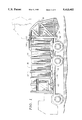
- FIG. 1 is a side view of a rear-loading refuse collection vehicle on which the tailgate locking mechanism of the present invention is utilized;
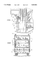
- FIG. 2 is a rear view of the rear-loading refuse collection vehicle of FIG. 1, partially cut away to illustrate the tailgate locking mechanism of the present invention
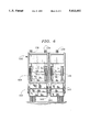
- FIG. 3 is a detailed side view of the tailgate locking mechanism of the present invention.
- FIG. 4 is a schematic diagram of the tailgate locking mechanism of the present invention showing the locking cylinders in an unlatched position
- FIG. 5 is a schematic diagram of the tailgate locking mechanism of the present invention showing the first locking cylinder in a latched position
- FIG. 6 is a rear view of an alternative refuse collection vehicle, partially cut away to illustrate an alternative embodiment of the present invention.
- a rear-loading refuse collection vehicle includes a wheel-supported truck chassis 10 on which is mounted a refuse container body 12.
- the container body has side walls 14 and 16, a top wall 18, a bottom wall 20, and an open rear end, the periphery of which is shown at 22.
- a rear-loading vehicle is illustrated, it will be appreciated that the present invention can be used with other types of refuse collection vehicles.
- a tailgate 30 is mounted on the top wall 18 of the container body by pivotal mountings 32.
- the pivotal mountings are positioned at the upper edge of the tailgate, with two pivotal mountings being provided, one at each side of the tailgate.
- the tailgate is swung upwardly about the pivotal mountings from a closed position, shown in FIG. 1, to a raised or open position, shown in phantom in FIG. 1, by the actuation of a pair of lifting cylinders 34.
- One end of each lifting cylinder is mounted to the top wall 18 of the container body, while the other end is mounted to the upper end of the tailgate 30.
- the tailgate need not be mounted to the top wall of the container, but can be mounted to the container body at other locations, such as the sides of the container body.
- the refuse collection vehicle is provided with a tailgate locking mechanism 36.
- the locking mechanism 36 includes a pair of hydraulic locking cylinders 38, 39 mounted adjacent to the rear end of the container body, with one hydraulic cylinder being provided at each side of the vehicle.
- the hydraulic cylinders 38, 39 latch the lower end of the tailgate 30 to the rear end of the container body 12 except when the tailgate is specifically released.
- the hydraulic locking cylinders 38, 39 operate sequentially so that the remote hydraulic cylinder 38, which is not visible to the vehicle's operator from the vehicle's driver side, is actuated first, and the second, visible hydraulic cylinder 39 is activated only after the remote cylinder has been latched or unlatched.
- the sequential operation insures that the hidden hydraulic cylinder is latched or unlatched before the visible cylinder moves, thus eliminating the need to visibly inspect the remote cylinder, or employ sensing devices to detect the position of the remote cylinder.
- the hydraulic locking cylinder 39 includes a piston assembly 40 comprising a piston rod 42 and a piston 44 (FIGS. 4 and 5).
- the piston assembly is disposed within a cylinder barrel 46.
- the cylinder assembly is mounted, at its base end, to the tailgate 30 by a mounting pin and bracket assembly 48, and at its rod end, by an apertured guide bracket 54.
- the hydraulic locking cylinder is positioned so that, when the piston rod 42 is fully extended, it is engaged with an apertured latch bracket 52, mounted to the container body 12, to lock the tailgate 30 to the container body.
- the piston rod is retracted, it is withdrawn from the latch bracket 52, as shown by broken lines in FIG. 3, to unlock the tailgate.
- the hydraulic locking cylinder 38 is similar in construction to the hydraulic locking cylinder 39, and includes a piston assembly 55 comprising a piston rod 56 and a piston 58.
- the piston assembly is disposed within a cylinder barrel 70 which is divided into a lower chamber 74 and an upper chamber 82.
- the lower chamber is defined, within the cylinder barrel 70, by a base end wall 76 and the piston 58, and the upper chamber 82 is defined, within the cylinder barrel, by the piston 58 and a rod end wall 80.
- the cylinder barrel 46 of the hydraulic locking cylinder 39 is divided into a lower chamber 92 and an upper chamber 98.
- the lower chamber is defined by a base end wall 94 and the piston 44
- the upper chamber 98 is defined by the piston 44 and a rod end wall 96.
- Hydraulic fluid from a fluid supply tank (not shown) is directed by a conventional directional control valve 62 to a line 64.
- the valve 62 is controlled by a control means 65 which is remote from the hydraulic locking cylinders.
- the control means can be positioned at the front lower corner of the container body.
- the line 64 directs the flow of fluid to a port 72 at the base of the hydraulic locking cylinder 38.
- a check valve 66 is positioned in the supply line 64 to insure that hydraulic fluid is prevented from reaching the hydraulic locking cylinder 39.
- the hydraulic fluid passes through the port 72 into the lower chamber 74, where the piston 58 blocks a port 102.
- hydraulic fluid in the upper chamber is exhausted out through a port 104 and is returned to the fluid supply tank by a line 106.
- the port 102 When the piston assembly 55 is fully extended into the latched position shown in FIG. 5, the port 102 is uncovered, allowing hydraulic fluid to pass out of the port and through a line 108 to a port 112 at the base of the hydraulic locking cylinder 39.
- the hydraulic fluid passes through the port 112 into the lower chamber 92, and fluid is exhausted from the upper chamber 98 through a port 114.
- the exhausted fluid passes through a one way check valve 116 and is returned to the fluid supply tank by the line 106. Hydraulic fluid continues to enter the lower chamber 92 until the piston assembly 40 is fully extended into the latched position.
- hydraulic fluid from the fluid supply tank is directed by the directional control valve 62 to the line 106 which directs the flow of fluid to the port 104.
- the one-way check valve 116 in the line 106 prevents the fluid from reaching the hydraulic locking cylinder 39, thus insuring that all the fluid is directed to the port 104.
- the hydraulic fluid passes through the port 104 into the upper chamber 82, where the piston 58 blocks a port 120.
- the piston 58 retracts and hydraulic fluid is exhausted from the lower chamber 74 through port 72 and line 64 back to the fluid supply tank.
- the port 120 is uncovered, allowing hydraulic fluid to pass through a line 122 to the port 114 in the hydraulic locking cylinder 39.
- the hydraulic fluid passes through the port 114 into the upper chamber 98, and fluid is exhausted from the lower chamber 92 through the port 112.
- the exhausted fluid passes through the one-way check valve 66 and is returned to the fluid supply tank by the line 64.
- the tailgate locking mechanism of the present invention operates fluidically in a sequential fashion to insure that the downstream visible hydraulic locking cylinder will latch or unlatch only after the upstream remote, or non-visible, hydraulic locking cylinder has latched or unlatched.
- the sequential operation thus eliminates the need to visibly inspect the remote locking cylinder, and eliminates the need for electronic sensors to detect the position of the remote locking cylinder.
- FIG. 6 there is shown the rear of a refuse vehicle, similar to the refuse vehicle of FIG. 1, except that the refuse container body 132 has a vertical divider (not shown) which divides the container body into left and right body compartments.
- a left and a right tailgate 134, 136, respectively, for closing the open rear ends of the left and right body compartments respectively, are pivotally mounted to the top wall of the container body 132.
- the tailgates are swung upwardly about their pivotal mountings from a closed position, shown in FIG. 6, to a raised or open position.
- the left tailgate 134 is raised and lowered by the actuation of a pair of lifting cylinders 138, 139, while the actuation of a single lifting cylinder 140 raises the right tailgate 136.
- Each of the tailgates 134 and 136 is locked in the closed position by a tailgate locking mechanism like that described in connection with FIGS. 1-5.
- Inner and outer hydraulic locking cylinders 142 and 143, respectively, are provided adjacent the inner and outer sides, respectively, of the tailgate 134, while inner and outer hydraulic locking cylinders 144 and 145, respectively, are provided adjacent the inner and outer sides, respectively, of the tailgate 136. Because the inner hydraulic locking cylinders 142 and 144 are hidden from view when the tailgates 134 and 136 are closed, it is virtually impossible to see whether the inner cylinders are locked or unlocked.
- the hydraulic locking cylinders 142, 143, 144 and 145 are therefore sequenced in the manner described in connection with FIGS. 4 and 5, so that the inner locking cylinders 142, 144 are actuated first. Only after the inner locking cylinders have been fully extended or retracted do the outer, visible locking cylinders 143 and 145 begin to move.
- the inner and outer locking cylinders 142 and 143 for the tailgate 134 are operated on one hydraulic circuit, while the inner and outer locking cylinders 144, 145 for the tailgate 136 are operated on a second, independent hydraulic circuit.
- This arrangement permits the tailgate 134 to be locked or unlocked separately from the tailgate 136.
- the hydraulic locking cylinders may be operated in series on the same hydraulic circuit, with each of the locking cylinders fluidically connected to the others.
- the hydraulic locking cylinders are sequenced so that either of the two inner locking cylinders 142 or 144 is actuated first, the other inner locking cylinder is second, the outer locking cylinder 145 is third, and the outer locking cylinder 143, which is visible to the vehicle operator, is actuated last.
- the sequencing mechanism is like that described in connection with FIGS. 4 and 5, so that the first actuated inner cylinder must be fully extended before fluid can be directed to the second inner cylinder, the second inner cylinder must be fully extended before the outer locking cylinder 145 receives the fluid, and the outer locking cylinder 145 must be fully extended before the visible outer locking cylinder 143 receives the fluid.
- the same sequence occurs when the cylinders are retracted.
- the present invention provides a simple and effective mechanism for locking the tailgate to the body of a refuse vehicle, without the need to inspect the remote or hidden locking cylinder or to employ multiple sensors to determine the locking position.
- the locking mechanism disclosed herein may be embodied in other specific forms without departing from the spirit or central characteristics thereof.
- the hydraulic locking cylinders illustrated in FIGS. 1-6 are mounted vertically on the refuse collection vehicle, it will be appreciated by those skilled in the art that the hydraulic locking cylinders can be mounted horizontally.
- the locking mechanism can be mounted so that the hydraulic locking cylinders are mounted on the container body and the apertured latch brackets are mounted on the tailgate.
- FIGS. 1 and 2 it may be desirable to employ three hydraulic locking cylinders, rather than two, for the single tailgate illustrated in FIGS. 1 and 2.
- the cylinders are mounted adjacent the rear end of the container body with one cylinder at each side of the body and one cylinder in the middle.
- the locking cylinders are sequenced so that the locking cylinder which is visible to an operator operating the control means receives hydraulic fluid last, only after the other two locking cylinders have been fully extended or retracted.
Landscapes
- Engineering & Computer Science (AREA)
- Mechanical Engineering (AREA)
- Lock And Its Accessories (AREA)
- Refuse-Collection Vehicles (AREA)
Abstract
Description
Claims (21)
Priority Applications (6)
| Application Number | Priority Date | Filing Date | Title |
|---|---|---|---|
| US08/053,907 US5413402A (en) | 1993-04-27 | 1993-04-27 | Sequenced tailgate lock |
| AU69039/94A AU6903994A (en) | 1993-04-27 | 1994-04-26 | Sequenced tailgate lock |
| EP94917270A EP0695242A4 (en) | 1993-04-27 | 1994-04-26 | Sequenced tailgate lock |
| CA002161090A CA2161090C (en) | 1993-04-27 | 1994-04-26 | Sequenced tailgate lock |
| PCT/US1994/004524 WO1994025308A1 (en) | 1993-04-27 | 1994-04-26 | Sequenced tailgate lock |
| US08/334,600 US5520443A (en) | 1993-04-27 | 1994-11-04 | Series hydraulic circuit tailgate locking mechanism |
Applications Claiming Priority (1)
| Application Number | Priority Date | Filing Date | Title |
|---|---|---|---|
| US08/053,907 US5413402A (en) | 1993-04-27 | 1993-04-27 | Sequenced tailgate lock |
Related Child Applications (1)
| Application Number | Title | Priority Date | Filing Date |
|---|---|---|---|
| US08/334,600 Continuation-In-Part US5520443A (en) | 1993-04-27 | 1994-11-04 | Series hydraulic circuit tailgate locking mechanism |
Publications (1)
| Publication Number | Publication Date |
|---|---|
| US5413402A true US5413402A (en) | 1995-05-09 |
Family
ID=21987348
Family Applications (2)
| Application Number | Title | Priority Date | Filing Date |
|---|---|---|---|
| US08/053,907 Expired - Lifetime US5413402A (en) | 1993-04-27 | 1993-04-27 | Sequenced tailgate lock |
| US08/334,600 Expired - Fee Related US5520443A (en) | 1993-04-27 | 1994-11-04 | Series hydraulic circuit tailgate locking mechanism |
Family Applications After (1)
| Application Number | Title | Priority Date | Filing Date |
|---|---|---|---|
| US08/334,600 Expired - Fee Related US5520443A (en) | 1993-04-27 | 1994-11-04 | Series hydraulic circuit tailgate locking mechanism |
Country Status (5)
| Country | Link |
|---|---|
| US (2) | US5413402A (en) |
| EP (1) | EP0695242A4 (en) |
| AU (1) | AU6903994A (en) |
| CA (1) | CA2161090C (en) |
| WO (1) | WO1994025308A1 (en) |
Cited By (8)
| Publication number | Priority date | Publication date | Assignee | Title |
|---|---|---|---|---|
| US5603536A (en) * | 1995-09-26 | 1997-02-18 | Applied Power Inc. | Linear preload fluid power operated latch |
| US6099048A (en) * | 1999-03-04 | 2000-08-08 | Ford Global Technologies, Inc. | Automotive door latching system |
| US20050039504A1 (en) * | 2003-08-20 | 2005-02-24 | Master Lock Company | Dead Locking Deadbolt |
| US20060006676A1 (en) * | 2004-06-29 | 2006-01-12 | Matthew Plett | Overstroke latch assembly |
| US9004842B2 (en) | 2011-10-10 | 2015-04-14 | Wastequip, Llc | Hoist apparatus |
| US20170057743A1 (en) * | 2015-08-25 | 2017-03-02 | Wayne Industrial Holdings, Llc | Refuse collection vehicle body with pendulum packer |
| US11173822B2 (en) | 2019-04-29 | 2021-11-16 | Ideal Latch Systems, L.L.C. | Safety latch for a dump body |
| US11976675B2 (en) | 2021-02-11 | 2024-05-07 | Xtreme Manufacturing, Llc | Systems and methods for bleed down and retraction of a construction machine boom |
Families Citing this family (6)
| Publication number | Priority date | Publication date | Assignee | Title |
|---|---|---|---|---|
| US5816766A (en) * | 1997-02-11 | 1998-10-06 | Toccoa Metal Technologies, Inc. | Refuse vehicle dumping system |
| US6408736B1 (en) | 1999-07-13 | 2002-06-25 | Welker Bearing Company | Synchronizing cylinder assembly with equal displacement hydraulic cylinder |
| NL1017987C2 (en) * | 2001-05-03 | 2002-11-05 | Actuant Corp | Hydraulic operating device, in particular for a cover cap assembly of a vehicle. |
| DE10126029B4 (en) * | 2001-05-28 | 2004-07-08 | Gkn Walterscheid Gmbh | Hydraulic hoist for an attachment |
| US6412877B1 (en) * | 2001-09-12 | 2002-07-02 | Willie F. Faison | Dump truck tailgate apparatus operable as either a rotatable or pivotable gate |
| FR2971023B1 (en) * | 2011-01-31 | 2014-07-11 | Poclain Hydraulics Ind | HYDRAULIC TRANSMISSION DEVICE FOR ENERGY RECOVERY |
Citations (5)
| Publication number | Priority date | Publication date | Assignee | Title |
|---|---|---|---|---|
| US2558867A (en) * | 1948-04-20 | 1951-07-03 | Westinghouse Air Brake Co | Door operating mechanism |
| US3111346A (en) * | 1957-05-17 | 1963-11-19 | Challenge Cook Bros Inc | Tilting dumping vehicle plural gate latch operating mechanism |
| US4068769A (en) * | 1975-07-02 | 1978-01-17 | American Carrier Equipment | Cargo box |
| US4109963A (en) * | 1977-03-30 | 1978-08-29 | Caterpillar Tractor Co. | Dump body gate latch control system |
| GB2093902A (en) * | 1980-12-16 | 1982-09-08 | Allen Jack Motor Bodies Ltd | Tailgate locking means |
Family Cites Families (3)
| Publication number | Priority date | Publication date | Assignee | Title |
|---|---|---|---|---|
| US3476016A (en) * | 1967-10-20 | 1969-11-04 | Cascade Corp | Apparatus for producing coordinated,simultaneous actuation of multiple rams |
| US3873149A (en) * | 1972-04-03 | 1975-03-25 | Helix Corp | Body and tailgate assembly for a truck or similar vehicle |
| US4585172A (en) * | 1983-10-07 | 1986-04-29 | The Garrett Corporation | Hydraulic actuation |
-
1993
- 1993-04-27 US US08/053,907 patent/US5413402A/en not_active Expired - Lifetime
-
1994
- 1994-04-26 CA CA002161090A patent/CA2161090C/en not_active Expired - Fee Related
- 1994-04-26 EP EP94917270A patent/EP0695242A4/en not_active Withdrawn
- 1994-04-26 WO PCT/US1994/004524 patent/WO1994025308A1/en not_active Ceased
- 1994-04-26 AU AU69039/94A patent/AU6903994A/en not_active Abandoned
- 1994-11-04 US US08/334,600 patent/US5520443A/en not_active Expired - Fee Related
Patent Citations (5)
| Publication number | Priority date | Publication date | Assignee | Title |
|---|---|---|---|---|
| US2558867A (en) * | 1948-04-20 | 1951-07-03 | Westinghouse Air Brake Co | Door operating mechanism |
| US3111346A (en) * | 1957-05-17 | 1963-11-19 | Challenge Cook Bros Inc | Tilting dumping vehicle plural gate latch operating mechanism |
| US4068769A (en) * | 1975-07-02 | 1978-01-17 | American Carrier Equipment | Cargo box |
| US4109963A (en) * | 1977-03-30 | 1978-08-29 | Caterpillar Tractor Co. | Dump body gate latch control system |
| GB2093902A (en) * | 1980-12-16 | 1982-09-08 | Allen Jack Motor Bodies Ltd | Tailgate locking means |
Cited By (12)
| Publication number | Priority date | Publication date | Assignee | Title |
|---|---|---|---|---|
| US5603536A (en) * | 1995-09-26 | 1997-02-18 | Applied Power Inc. | Linear preload fluid power operated latch |
| US6099048A (en) * | 1999-03-04 | 2000-08-08 | Ford Global Technologies, Inc. | Automotive door latching system |
| US20050039504A1 (en) * | 2003-08-20 | 2005-02-24 | Master Lock Company | Dead Locking Deadbolt |
| US20060006676A1 (en) * | 2004-06-29 | 2006-01-12 | Matthew Plett | Overstroke latch assembly |
| US7243973B2 (en) | 2004-06-29 | 2007-07-17 | Honda Motor Co., Ltd. | Overstroke latch assembly |
| US20070222230A1 (en) * | 2004-06-29 | 2007-09-27 | Honda Motor Co., Ltd. | Overstroke latch assembly |
| US8469409B2 (en) | 2004-06-29 | 2013-06-25 | Honda Motor Co., Ltd. | Overstroke latch assembly |
| US9004842B2 (en) | 2011-10-10 | 2015-04-14 | Wastequip, Llc | Hoist apparatus |
| US20170057743A1 (en) * | 2015-08-25 | 2017-03-02 | Wayne Industrial Holdings, Llc | Refuse collection vehicle body with pendulum packer |
| US9764894B2 (en) * | 2015-08-25 | 2017-09-19 | Wayne Industrial Holdings, Llc | Refuse collection vehicle body with pendulum packer |
| US11173822B2 (en) | 2019-04-29 | 2021-11-16 | Ideal Latch Systems, L.L.C. | Safety latch for a dump body |
| US11976675B2 (en) | 2021-02-11 | 2024-05-07 | Xtreme Manufacturing, Llc | Systems and methods for bleed down and retraction of a construction machine boom |
Also Published As
| Publication number | Publication date |
|---|---|
| CA2161090A1 (en) | 1994-11-10 |
| EP0695242A1 (en) | 1996-02-07 |
| WO1994025308A1 (en) | 1994-11-10 |
| EP0695242A4 (en) | 1998-01-07 |
| CA2161090C (en) | 2004-02-24 |
| US5520443A (en) | 1996-05-28 |
| AU6903994A (en) | 1994-11-21 |
Similar Documents
| Publication | Publication Date | Title |
|---|---|---|
| US5413402A (en) | Sequenced tailgate lock | |
| US5816766A (en) | Refuse vehicle dumping system | |
| US3851867A (en) | Pneumatic actuator control apparatus | |
| US3615029A (en) | Rear loading refuse vehicle | |
| US6196634B1 (en) | Dumping bed liner for pickup truck | |
| US3873149A (en) | Body and tailgate assembly for a truck or similar vehicle | |
| US2654491A (en) | Vehicle lift gate | |
| US3232463A (en) | Refuse collection and packer body | |
| US4057157A (en) | Load compacting and ejecting mechanism for a refuse truck | |
| CA2186214A1 (en) | Locking mechanism for a trailer door | |
| US3797882A (en) | Hydraulic system and mechanical latch therefor | |
| US5498067A (en) | Lifting latch hinge for tailgate on refuse hauler/compactor | |
| US4361985A (en) | Hydraulic door opening/closing and locking/unlocking apparatus | |
| US4762345A (en) | Air operated positive lock for refuse trailer and the like | |
| CA2016376C (en) | Combined tailgate and loader assembly for a dump truck | |
| US5197782A (en) | Apparatus including a vehicle and a container for use in hauling and dumping material | |
| US5299856A (en) | Dump vehicle with hydraulic lock for material holding container | |
| US6764126B2 (en) | Hydraulic actuating device for a cover with associated lock | |
| JPH0717154B2 (en) | Drive for the cover | |
| EP3611119A1 (en) | Feed charging bridge and method for operating the same | |
| US3825295A (en) | Truck cab latch | |
| CN206598706U (en) | Vehicular end gate hydraulic pressure overturns block sytem and vehicle | |
| US6170916B1 (en) | Tailgate operating assembly | |
| US11173682B2 (en) | Automatic door sequencing for discharging refuse from multi-compartment packer | |
| GB2093902A (en) | Tailgate locking means |
Legal Events
| Date | Code | Title | Description |
|---|---|---|---|
| STPP | Information on status: patent application and granting procedure in general |
Free format text: APPLICATION UNDERGOING PREEXAM PROCESSING |
|
| AS | Assignment |
Owner name: HEIL CO., THE, TENNESSEE Free format text: ASSIGNMENT OF ASSIGNORS INTEREST;ASSIGNORS:FLERCHINGER, GARY G.;ZANZIG, JERALD G.;REEL/FRAME:006595/0682 Effective date: 19930622 |
|
| AS | Assignment |
Owner name: DELAWARE CAPITAL FORMATION INC., DELAWARE Free format text: ASSIGNMENT OF ASSIGNORS INTEREST;ASSIGNOR:HEIL CO., THE;REEL/FRAME:008943/0119 Effective date: 19971219 |
|
| FPAY | Fee payment |
Year of fee payment: 4 |
|
| FEPP | Fee payment procedure |
Free format text: PAYOR NUMBER ASSIGNED (ORIGINAL EVENT CODE: ASPN); ENTITY STATUS OF PATENT OWNER: LARGE ENTITY |
|
| FPAY | Fee payment |
Year of fee payment: 8 |
|
| AS | Assignment |
Owner name: CP FORMATION LLC, DELAWARE Free format text: ASSIGNMENT OF ASSIGNORS INTEREST;ASSIGNOR:DELAWARE CAPITAL FORMATION, INC.;REEL/FRAME:016602/0853 Effective date: 20041231 Owner name: HEIL COMPANY, THE, TENNESSEE Free format text: ASSIGNMENT OF ASSIGNORS INTEREST;ASSIGNOR:CP FORMATION LLC;REEL/FRAME:016602/0083 Effective date: 20050102 |
|
| FPAY | Fee payment |
Year of fee payment: 12 |