US5411368A - Ceramic-to-metal stator vane assembly with braze - Google Patents
Ceramic-to-metal stator vane assembly with braze Download PDFInfo
- Publication number
- US5411368A US5411368A US08/148,483 US14848393A US5411368A US 5411368 A US5411368 A US 5411368A US 14848393 A US14848393 A US 14848393A US 5411368 A US5411368 A US 5411368A
- Authority
- US
- United States
- Prior art keywords
- ceramic
- sleeves
- vanes
- metallic
- stator
- Prior art date
- Legal status (The legal status is an assumption and is not a legal conclusion. Google has not performed a legal analysis and makes no representation as to the accuracy of the status listed.)
- Expired - Fee Related
Links
Images

Classifications
-
- F—MECHANICAL ENGINEERING; LIGHTING; HEATING; WEAPONS; BLASTING
- F01—MACHINES OR ENGINES IN GENERAL; ENGINE PLANTS IN GENERAL; STEAM ENGINES
- F01D—NON-POSITIVE DISPLACEMENT MACHINES OR ENGINES, e.g. STEAM TURBINES
- F01D9/00—Stators
- F01D9/02—Nozzles; Nozzle boxes; Stator blades; Guide conduits, e.g. individual nozzles
- F01D9/04—Nozzles; Nozzle boxes; Stator blades; Guide conduits, e.g. individual nozzles forming ring or sector
- F01D9/042—Nozzles; Nozzle boxes; Stator blades; Guide conduits, e.g. individual nozzles forming ring or sector fixing blades to stators
- F01D9/044—Nozzles; Nozzle boxes; Stator blades; Guide conduits, e.g. individual nozzles forming ring or sector fixing blades to stators permanently, e.g. by welding, brazing, casting or the like
-
- F—MECHANICAL ENGINEERING; LIGHTING; HEATING; WEAPONS; BLASTING
- F05—INDEXING SCHEMES RELATING TO ENGINES OR PUMPS IN VARIOUS SUBCLASSES OF CLASSES F01-F04
- F05D—INDEXING SCHEME FOR ASPECTS RELATING TO NON-POSITIVE-DISPLACEMENT MACHINES OR ENGINES, GAS-TURBINES OR JET-PROPULSION PLANTS
- F05D2230/00—Manufacture
- F05D2230/20—Manufacture essentially without removing material
-
- F—MECHANICAL ENGINEERING; LIGHTING; HEATING; WEAPONS; BLASTING
- F05—INDEXING SCHEMES RELATING TO ENGINES OR PUMPS IN VARIOUS SUBCLASSES OF CLASSES F01-F04
- F05D—INDEXING SCHEME FOR ASPECTS RELATING TO NON-POSITIVE-DISPLACEMENT MACHINES OR ENGINES, GAS-TURBINES OR JET-PROPULSION PLANTS
- F05D2300/00—Materials; Properties thereof
- F05D2300/20—Oxide or non-oxide ceramics
- F05D2300/21—Oxide ceramics
-
- Y—GENERAL TAGGING OF NEW TECHNOLOGICAL DEVELOPMENTS; GENERAL TAGGING OF CROSS-SECTIONAL TECHNOLOGIES SPANNING OVER SEVERAL SECTIONS OF THE IPC; TECHNICAL SUBJECTS COVERED BY FORMER USPC CROSS-REFERENCE ART COLLECTIONS [XRACs] AND DIGESTS
- Y10—TECHNICAL SUBJECTS COVERED BY FORMER USPC
- Y10T—TECHNICAL SUBJECTS COVERED BY FORMER US CLASSIFICATION
- Y10T29/00—Metal working
- Y10T29/49—Method of mechanical manufacture
- Y10T29/49316—Impeller making
- Y10T29/4932—Turbomachine making
- Y10T29/49323—Assembling fluid flow directing devices, e.g., stators, diaphragms, nozzles
-
- Y—GENERAL TAGGING OF NEW TECHNOLOGICAL DEVELOPMENTS; GENERAL TAGGING OF CROSS-SECTIONAL TECHNOLOGIES SPANNING OVER SEVERAL SECTIONS OF THE IPC; TECHNICAL SUBJECTS COVERED BY FORMER USPC CROSS-REFERENCE ART COLLECTIONS [XRACs] AND DIGESTS
- Y10—TECHNICAL SUBJECTS COVERED BY FORMER USPC
- Y10T—TECHNICAL SUBJECTS COVERED BY FORMER US CLASSIFICATION
- Y10T29/00—Metal working
- Y10T29/49—Method of mechanical manufacture
- Y10T29/49826—Assembling or joining
- Y10T29/49863—Assembling or joining with prestressing of part
- Y10T29/49865—Assembling or joining with prestressing of part by temperature differential [e.g., shrink fit]
-
- Y—GENERAL TAGGING OF NEW TECHNOLOGICAL DEVELOPMENTS; GENERAL TAGGING OF CROSS-SECTIONAL TECHNOLOGIES SPANNING OVER SEVERAL SECTIONS OF THE IPC; TECHNICAL SUBJECTS COVERED BY FORMER USPC CROSS-REFERENCE ART COLLECTIONS [XRACs] AND DIGESTS
- Y10—TECHNICAL SUBJECTS COVERED BY FORMER USPC
- Y10T—TECHNICAL SUBJECTS COVERED BY FORMER US CLASSIFICATION
- Y10T403/00—Joints and connections
- Y10T403/21—Utilizing thermal characteristic, e.g., expansion or contraction, etc.
-
- Y—GENERAL TAGGING OF NEW TECHNOLOGICAL DEVELOPMENTS; GENERAL TAGGING OF CROSS-SECTIONAL TECHNOLOGIES SPANNING OVER SEVERAL SECTIONS OF THE IPC; TECHNICAL SUBJECTS COVERED BY FORMER USPC CROSS-REFERENCE ART COLLECTIONS [XRACs] AND DIGESTS
- Y10—TECHNICAL SUBJECTS COVERED BY FORMER USPC
- Y10T—TECHNICAL SUBJECTS COVERED BY FORMER US CLASSIFICATION
- Y10T403/00—Joints and connections
- Y10T403/48—Shrunk fit
Definitions
- This invention relates to gas turbine engines, and in particular, to a stator vane assembly having ceramic stator vanes mounted to a metallic support structure.
- stator vane assembly in a gas turbine engine in which ceramic stator vanes are mounted to a metallic support structure in such a way so as accommodate the thermal mismatch between ceramic and metallic.
- An object of the present invention is to provide a stator vane assembly for gas turbine engines having ceramic stator vanes.
- Another object of the present invention is to provide a method for mounting ceramic stator vanes in a gas turbine engine.
- the present invention achieves these objectives by providing a stator vane assembly for a gas turbine engine that includes a plurality of circumferentially spaced ceramic vanes, each of which has an inner and outer ceramic shroud, and a ceramic post extending from one of the shrouds, and a metallic platform having a plurality of circumferentially spaced recesses.
- the posts are inserted into a metallic sleeve and then brazed.
- the brazed sleeves are then mounted in the recesses.
- a method for assembling these components to form the stator assembly is also described.
- the braze is flexible and accommodates the thermal mismatch between the ceramic post and metallic sleeve, while the sleeve protects the brittle ceramic post.
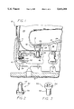
- FIG. 1 is a cross sectional view of a portion of a gas turbine engine having a stator vane assembly contemplated by the present invention.
- FIGS. 2 and 3 are two different perspective views of the metal sleeve of the stator vane assembly of FIG. 1.
- FIG. 4 is a perspective view of a stator vane and sleeve of the stator vane assembly of FIG. 1.
- FIG. 5 is a perspective view of annular support structure 38.
- FIG. 1 shows a partial view of the turbine section 10 of a gas turbine engine.
- the turbine section 10 is conventional in that it has a nonrotating metallic casing, that includes walls 11 and 13, circumscribing a rotating shaft 14 to define a flow path 16 therebetween.
- the flow path 16 extends axially, parallel to the engine's center line 18, from the combustor 20 towards the engine's exhaust, not shown.
- Operably disposed within the flow path 16 are a plurality of stator assemblies 22, 26 and rotor assemblies 24, 28.
- the stator assemblies 22, 26 are mounted to the metallic casing and the rotor assemblies 24, 28 are mounted to the shaft 14.
- the hot gas exiting the combustor 20 is expanded across the turbine section 10 causing the rotor assemblies 24, 28, and hence the shaft 14 to rotate.
- the stator assembly 22 includes a plurality of stator vanes 30, also referred to as nozzles.
- Each vane 30 is bounded radially, relative to the engine centerline 18, by an inner shroud 32 and an outer shroud 34.
- Extending radially inward from the inner shroud 32 is a post 36.
- the post 36 is preferably cylindrical, though other shapes are contemplated to work as effectively.
- the post 36 can be curved.
- the vane 30, shrouds 32, 34, and post 36 are all integrally formed from a ceramic such as silicon carbide or silicon nitride.
- the vanes 30 are formed with the post 36 off center from the radial centerline of the vane 30.
- the stator assembly 22 further includes an annular metallic support structure 38.
- the shape and configuration of the structure 38 can vary greatly depending on the particular engine in which it is mounted, and on the particular stator assembly receiving the ceramic vanes 30.
- the support structure 38 has a radially extending annular wall 40 having bolt holes 41 and cooling air holes 43. Extending axially from the wall 40 toward the rear of the engine are two radially spaced walls 42 and 44.
- the inner wall 42 has a flat inner surface that, after mounting, abuts a seal 39 that is part of the rotor assembly 24.
- the outer wall 44 extends further than the inner wall 42 and has at its axial end a platform 46 having a plurality of circumferentially spaced recesses 48.
- the outer wall 44 may be hollow.
- a metal sleeve 50 is used for mounting each stator vane 30 to the platform 46.
- the sleeve 50 is made from metal alloy, such as Inconel 4005, having a low thermal expansion coefficient.
- the sleeve 50 is comprised of a tube portion 52 and a base portion 54. Of course, the diameter and shape of the tube portion 52 is selected so that it can receive the post 36.
- a braze alloy 60 is disposed, in a manner familiar to those skilled, between the inner surface of the sleeve 50 and the outer surface of the post 36.
- the braze alloy is Gold Nickel (82 18) available from GTE-WESGO under the name of "Nioro".
- the tube 52 shrinks down around the post 36 resulting in a brazed and shrink fit attachment.
- the base portion 54 is then mounted in one of the recesses 48 in the platform 46 and bolted thereto.
- the base portion could be secured to the platform 46 by a pinned attachment, a dovetail attachment, a braze, or a weld.
- the vanes 30 remain fixed relative to the support structure 38 despite temperature changes in the gas.
- the braze is flexible and accommodates the thermal mismatch between the ceramic post 36 and metallic sleeve 50, while the sleeve 50 protects the brittle ceramic post 36 from contact with the surrounding metal structure.
Landscapes
- Engineering & Computer Science (AREA)
- Mechanical Engineering (AREA)
- General Engineering & Computer Science (AREA)
- Turbine Rotor Nozzle Sealing (AREA)
Abstract
Description
Claims (4)
Priority Applications (5)
| Application Number | Priority Date | Filing Date | Title |
|---|---|---|---|
| US08/148,483 US5411368A (en) | 1993-11-08 | 1993-11-08 | Ceramic-to-metal stator vane assembly with braze |
| DE69416316T DE69416316T2 (en) | 1993-11-08 | 1994-11-07 | SOLDERING CERAMIC WITH METAL FOR ASSEMBLY OF VANE |
| PCT/US1994/012667 WO1995013455A1 (en) | 1993-11-08 | 1994-11-07 | Ceramic-to-metal stator vane assembly with braze |
| EP95902437A EP0728257B1 (en) | 1993-11-08 | 1994-11-07 | Ceramic-to-metal stator vane assembly with braze |
| JP7513882A JPH09505377A (en) | 1993-11-08 | 1994-11-07 | Ceramic / metal stator blade device with brazing part |
Applications Claiming Priority (1)
| Application Number | Priority Date | Filing Date | Title |
|---|---|---|---|
| US08/148,483 US5411368A (en) | 1993-11-08 | 1993-11-08 | Ceramic-to-metal stator vane assembly with braze |
Publications (1)
| Publication Number | Publication Date |
|---|---|
| US5411368A true US5411368A (en) | 1995-05-02 |
Family
ID=22525980
Family Applications (1)
| Application Number | Title | Priority Date | Filing Date |
|---|---|---|---|
| US08/148,483 Expired - Fee Related US5411368A (en) | 1993-11-08 | 1993-11-08 | Ceramic-to-metal stator vane assembly with braze |
Country Status (5)
| Country | Link |
|---|---|
| US (1) | US5411368A (en) |
| EP (1) | EP0728257B1 (en) |
| JP (1) | JPH09505377A (en) |
| DE (1) | DE69416316T2 (en) |
| WO (1) | WO1995013455A1 (en) |
Cited By (9)
| Publication number | Priority date | Publication date | Assignee | Title |
|---|---|---|---|---|
| US6000906A (en) * | 1997-09-12 | 1999-12-14 | Alliedsignal Inc. | Ceramic airfoil |
| US20040086380A1 (en) * | 2001-02-13 | 2004-05-06 | Honeywell International Inc. | Face seal assembly with composite stator |
| US20060171812A1 (en) * | 2005-02-02 | 2006-08-03 | Siemens Westinghouse Power Corporation | Support system for a composite airfoil in a turbine engine |
| EP1790827A1 (en) * | 2005-11-29 | 2007-05-30 | General Electric Company | Tip shroud attachment for stator vane |
| EP1362983A3 (en) * | 2002-05-15 | 2007-12-05 | General Electric Company | Ceramic turbine shroud |
| US20080267771A1 (en) * | 2007-01-18 | 2008-10-30 | Beeck Alexander R | Gas turbine with a guide vane |
| US8784052B2 (en) | 2010-05-10 | 2014-07-22 | Hamilton Sundstrand Corporation | Ceramic gas turbine shroud |
| US20140234118A1 (en) * | 2011-04-28 | 2014-08-21 | Snecma | Turbine engine comprising a metal protection for a composite part |
| US9169736B2 (en) | 2012-07-16 | 2015-10-27 | United Technologies Corporation | Joint between airfoil and shroud |
Families Citing this family (1)
| Publication number | Priority date | Publication date | Assignee | Title |
|---|---|---|---|---|
| DE19950417A1 (en) * | 1999-10-20 | 2001-04-26 | Abb Patent Gmbh | Component for gas turbine, with base body and protective covering made of ceramic material |
Citations (18)
| Publication number | Priority date | Publication date | Assignee | Title |
|---|---|---|---|---|
| US2834537A (en) * | 1954-01-18 | 1958-05-13 | Ryan Aeronautical Co | Compressor stator structure |
| US3708242A (en) * | 1969-12-01 | 1973-01-02 | Snecma | Supporting structure for the blades of turbomachines |
| US3836282A (en) * | 1973-03-28 | 1974-09-17 | United Aircraft Corp | Stator vane support and construction thereof |
| US3849023A (en) * | 1973-06-28 | 1974-11-19 | Gen Electric | Stator assembly |
| US3857649A (en) * | 1973-08-09 | 1974-12-31 | Westinghouse Electric Corp | Inlet vane structure for turbines |
| US3867065A (en) * | 1973-07-16 | 1975-02-18 | Westinghouse Electric Corp | Ceramic insulator for a gas turbine blade structure |
| US3966353A (en) * | 1975-02-21 | 1976-06-29 | Westinghouse Electric Corporation | Ceramic-to-metal (or ceramic) cushion/seal for use with three piece ceramic stationary vane assembly |
| US4009969A (en) * | 1974-09-26 | 1977-03-01 | Ckd Praha, Oborovy Podnik | Supporting ring for stator vanes in an axial compressor |
| US4053257A (en) * | 1976-02-20 | 1977-10-11 | Westinghouse Electric Corporation | Stator vane assembly for gas turbines |
| US4076451A (en) * | 1976-03-05 | 1978-02-28 | United Technologies Corporation | Ceramic turbine stator |
| US4722630A (en) * | 1985-09-20 | 1988-02-02 | The Garrett Corporation | Ceramic-metal braze joint |
| US4798320A (en) * | 1985-09-20 | 1989-01-17 | Allied-Signal Inc. | Ceramic-metal brazed joint for turbochargers |
| US5073085A (en) * | 1988-12-16 | 1991-12-17 | Ngk Spark Plug Co., Ltd. | Ceramic turbocharger rotor |
| US5074752A (en) * | 1990-08-06 | 1991-12-24 | General Electric Company | Gas turbine outlet guide vane mounting assembly |
| US5074749A (en) * | 1989-05-23 | 1991-12-24 | Societe Europeenne De Propulsion | Turbine stator for a turbojet, and method of manufacture |
| US5104747A (en) * | 1989-10-04 | 1992-04-14 | Kabushiki Kaisha Toyota Chuo Kenkyusho | Joined assembly of ceramic and metallic materials |
| US5105625A (en) * | 1990-11-23 | 1992-04-21 | General Motors Corporation | Mounting for a ceramic scroll in a gas turbine machine |
| US5129783A (en) * | 1989-09-22 | 1992-07-14 | Rolls-Royce Plc | Gas turbine engines |
Family Cites Families (1)
| Publication number | Priority date | Publication date | Assignee | Title |
|---|---|---|---|---|
| GB2234299B (en) * | 1989-07-06 | 1994-01-05 | Rolls Royce Plc | Mounting system for engine components having dissimilar coefficients of thermal expansion |
-
1993
- 1993-11-08 US US08/148,483 patent/US5411368A/en not_active Expired - Fee Related
-
1994
- 1994-11-07 WO PCT/US1994/012667 patent/WO1995013455A1/en not_active Ceased
- 1994-11-07 DE DE69416316T patent/DE69416316T2/en not_active Expired - Fee Related
- 1994-11-07 JP JP7513882A patent/JPH09505377A/en active Pending
- 1994-11-07 EP EP95902437A patent/EP0728257B1/en not_active Expired - Lifetime
Patent Citations (18)
| Publication number | Priority date | Publication date | Assignee | Title |
|---|---|---|---|---|
| US2834537A (en) * | 1954-01-18 | 1958-05-13 | Ryan Aeronautical Co | Compressor stator structure |
| US3708242A (en) * | 1969-12-01 | 1973-01-02 | Snecma | Supporting structure for the blades of turbomachines |
| US3836282A (en) * | 1973-03-28 | 1974-09-17 | United Aircraft Corp | Stator vane support and construction thereof |
| US3849023A (en) * | 1973-06-28 | 1974-11-19 | Gen Electric | Stator assembly |
| US3867065A (en) * | 1973-07-16 | 1975-02-18 | Westinghouse Electric Corp | Ceramic insulator for a gas turbine blade structure |
| US3857649A (en) * | 1973-08-09 | 1974-12-31 | Westinghouse Electric Corp | Inlet vane structure for turbines |
| US4009969A (en) * | 1974-09-26 | 1977-03-01 | Ckd Praha, Oborovy Podnik | Supporting ring for stator vanes in an axial compressor |
| US3966353A (en) * | 1975-02-21 | 1976-06-29 | Westinghouse Electric Corporation | Ceramic-to-metal (or ceramic) cushion/seal for use with three piece ceramic stationary vane assembly |
| US4053257A (en) * | 1976-02-20 | 1977-10-11 | Westinghouse Electric Corporation | Stator vane assembly for gas turbines |
| US4076451A (en) * | 1976-03-05 | 1978-02-28 | United Technologies Corporation | Ceramic turbine stator |
| US4722630A (en) * | 1985-09-20 | 1988-02-02 | The Garrett Corporation | Ceramic-metal braze joint |
| US4798320A (en) * | 1985-09-20 | 1989-01-17 | Allied-Signal Inc. | Ceramic-metal brazed joint for turbochargers |
| US5073085A (en) * | 1988-12-16 | 1991-12-17 | Ngk Spark Plug Co., Ltd. | Ceramic turbocharger rotor |
| US5074749A (en) * | 1989-05-23 | 1991-12-24 | Societe Europeenne De Propulsion | Turbine stator for a turbojet, and method of manufacture |
| US5129783A (en) * | 1989-09-22 | 1992-07-14 | Rolls-Royce Plc | Gas turbine engines |
| US5104747A (en) * | 1989-10-04 | 1992-04-14 | Kabushiki Kaisha Toyota Chuo Kenkyusho | Joined assembly of ceramic and metallic materials |
| US5074752A (en) * | 1990-08-06 | 1991-12-24 | General Electric Company | Gas turbine outlet guide vane mounting assembly |
| US5105625A (en) * | 1990-11-23 | 1992-04-21 | General Motors Corporation | Mounting for a ceramic scroll in a gas turbine machine |
Non-Patent Citations (4)
| Title |
|---|
| Technical Paper entitled "Ceramics-to-Metal Joining Technology for Gas Turbine Rotors" by T. Sakamoto, H. Horinouchi and T. Maeda (pp. 1-6), copyright 1988, SAE, Inc. |
| Technical Paper entitled "Development of Brazing Technology for Ceramic Turbocharger Rotors" by Masaya Ito, Noboru Ishida and Norio Kato (pp. 55-63), presented at the Gas Turbine and Aeroengine congress and Exposition, Jun. 4-8, 1989, Toronto, Ontario, Canada. |
| Technical Paper entitled Ceramics to Metal Joining Technology for Gas Turbine Rotors by T. Sakamoto, H. Horinouchi and T. Maeda (pp. 1 6), copyright 1988, SAE, Inc. * |
| Technical Paper entitled Development of Brazing Technology for Ceramic Turbocharger Rotors by Masaya Ito, Noboru Ishida and Norio Kato (pp. 55 63), presented at the Gas Turbine and Aeroengine congress and Exposition, Jun. 4 8, 1989, Toronto, Ontario, Canada. * |
Cited By (15)
| Publication number | Priority date | Publication date | Assignee | Title |
|---|---|---|---|---|
| US6000906A (en) * | 1997-09-12 | 1999-12-14 | Alliedsignal Inc. | Ceramic airfoil |
| US20040086380A1 (en) * | 2001-02-13 | 2004-05-06 | Honeywell International Inc. | Face seal assembly with composite stator |
| US6918594B2 (en) | 2001-02-13 | 2005-07-19 | Honeywell International, Inc. | Face seal assembly with composite stator |
| CZ302320B6 (en) * | 2002-05-15 | 2011-03-09 | General Electric Company | Gas turbine |
| EP1362983A3 (en) * | 2002-05-15 | 2007-12-05 | General Electric Company | Ceramic turbine shroud |
| US7326030B2 (en) | 2005-02-02 | 2008-02-05 | Siemens Power Generation, Inc. | Support system for a composite airfoil in a turbine engine |
| US20060171812A1 (en) * | 2005-02-02 | 2006-08-03 | Siemens Westinghouse Power Corporation | Support system for a composite airfoil in a turbine engine |
| EP1790827A1 (en) * | 2005-11-29 | 2007-05-30 | General Electric Company | Tip shroud attachment for stator vane |
| US20070122274A1 (en) * | 2005-11-29 | 2007-05-31 | General Electric Company | Tip shroud attachment for stator vane |
| US20080267771A1 (en) * | 2007-01-18 | 2008-10-30 | Beeck Alexander R | Gas turbine with a guide vane |
| US8257032B2 (en) * | 2007-01-18 | 2012-09-04 | Siemens Aktiengesellschaft | Gas turbine with a guide vane |
| US8784052B2 (en) | 2010-05-10 | 2014-07-22 | Hamilton Sundstrand Corporation | Ceramic gas turbine shroud |
| US20140234118A1 (en) * | 2011-04-28 | 2014-08-21 | Snecma | Turbine engine comprising a metal protection for a composite part |
| US9638042B2 (en) * | 2011-04-28 | 2017-05-02 | Snecma | Turbine engine comprising a metal protection for a composite part |
| US9169736B2 (en) | 2012-07-16 | 2015-10-27 | United Technologies Corporation | Joint between airfoil and shroud |
Also Published As
| Publication number | Publication date |
|---|---|
| DE69416316T2 (en) | 1999-08-26 |
| JPH09505377A (en) | 1997-05-27 |
| DE69416316D1 (en) | 1999-03-11 |
| WO1995013455A1 (en) | 1995-05-18 |
| EP0728257B1 (en) | 1999-01-27 |
| EP0728257A1 (en) | 1996-08-28 |
Similar Documents
| Publication | Publication Date | Title |
|---|---|---|
| US6000906A (en) | Ceramic airfoil | |
| US6511294B1 (en) | Reduced-stress compressor blisk flowpath | |
| CA1333472C (en) | Compressor diaphragm assembly | |
| JP2628604B2 (en) | Combustion diaphragm assembly for combustion turbine and method of assembling the same | |
| EP1247944B1 (en) | Gas turbine frame | |
| US6543996B2 (en) | Hybrid turbine nozzle | |
| US5078576A (en) | Mounting system for engine components having dissimilar coefficients of thermal expansion | |
| EP3023581B1 (en) | Turbine disk assembly including ceramic matrix composite blades and method of manufacture | |
| US5653581A (en) | Case-tied joint for compressor stators | |
| US5609471A (en) | Multiproperty rotor disk and method of manufacture | |
| GB2094895A (en) | Turbine blade | |
| US6409473B1 (en) | Low stress connection methodology for thermally incompatible materials | |
| US5411368A (en) | Ceramic-to-metal stator vane assembly with braze | |
| US8172522B2 (en) | Method and system for supporting stator components | |
| EP1132576B1 (en) | Turbine shroud comprising an apparatus for minimizing thermal gradients and method for assembling a gas turbine engine including such a shroud | |
| EP2733308A2 (en) | Turbine engines with ceramic vanes and methods for manufacturing the same | |
| WO2014105425A1 (en) | Turbine frame assembly and method of designing turbine frame assembly | |
| CA2370219A1 (en) | Shroud assembly and method of machining same | |
| CA2048779A1 (en) | Attenuating shroud support | |
| EP3508700B1 (en) | Boas having radially extended protrusions | |
| US20210180521A1 (en) | Insert-mounted turbine assembly for a gas turbine engine | |
| US10767496B2 (en) | Turbine blade assembly with mounted platform | |
| US6234750B1 (en) | Interlocked compressor stator | |
| CA2660179A1 (en) | A system and method for supporting stator components | |
| US5156525A (en) | Turbine assembly |
Legal Events
| Date | Code | Title | Description |
|---|---|---|---|
| AS | Assignment |
Owner name: ALLIEDSIGNAL INC., NEW JERSEY Free format text: ASSIGNMENT OF ASSIGNORS INTEREST;ASSIGNORS:CHASE, DONNA J.;FANG, HO T.;IRWIN, CRAIG W.;AND OTHERS;REEL/FRAME:006785/0216;SIGNING DATES FROM 19931105 TO 19931108 |
|
| FEPP | Fee payment procedure |
Free format text: PAYOR NUMBER ASSIGNED (ORIGINAL EVENT CODE: ASPN); ENTITY STATUS OF PATENT OWNER: LARGE ENTITY |
|
| FEPP | Fee payment procedure |
Free format text: PAYER NUMBER DE-ASSIGNED (ORIGINAL EVENT CODE: RMPN); ENTITY STATUS OF PATENT OWNER: LARGE ENTITY Free format text: PAYOR NUMBER ASSIGNED (ORIGINAL EVENT CODE: ASPN); ENTITY STATUS OF PATENT OWNER: LARGE ENTITY |
|
| FPAY | Fee payment |
Year of fee payment: 4 |
|
| FPAY | Fee payment |
Year of fee payment: 8 |
|
| REMI | Maintenance fee reminder mailed | ||
| LAPS | Lapse for failure to pay maintenance fees | ||
| STCH | Information on status: patent discontinuation |
Free format text: PATENT EXPIRED DUE TO NONPAYMENT OF MAINTENANCE FEES UNDER 37 CFR 1.362 |
|
| FP | Lapsed due to failure to pay maintenance fee |
Effective date: 20070502 |