US5403161A - Air foil blade and methods of making same - Google Patents
Air foil blade and methods of making same Download PDFInfo
- Publication number
- US5403161A US5403161A US08/180,099 US18009994A US5403161A US 5403161 A US5403161 A US 5403161A US 18009994 A US18009994 A US 18009994A US 5403161 A US5403161 A US 5403161A
- Authority
- US
- United States
- Prior art keywords
- blade
- flange portion
- turbine
- airfoil
- airfoil blade
- Prior art date
- Legal status (The legal status is an assumption and is not a legal conclusion. Google has not performed a legal analysis and makes no representation as to the accuracy of the status listed.)
- Expired - Lifetime
Links
- 238000000034 method Methods 0.000 title claims description 11
- 239000011888 foil Substances 0.000 title abstract description 46
- 239000004743 Polypropylene Substances 0.000 claims abstract description 9
- -1 polypropylene Polymers 0.000 claims abstract description 9
- 229920001155 polypropylene Polymers 0.000 claims abstract description 9
- 238000001746 injection moulding Methods 0.000 claims abstract description 5
- 210000003850 cellular structure Anatomy 0.000 claims abstract description 3
- 229920001169 thermoplastic Polymers 0.000 claims description 14
- 239000004416 thermosoftening plastic Substances 0.000 claims description 14
- 229910052751 metal Inorganic materials 0.000 claims description 12
- 239000002184 metal Substances 0.000 claims description 12
- 239000000203 mixture Substances 0.000 claims description 9
- 239000004088 foaming agent Substances 0.000 claims description 8
- 230000000087 stabilizing effect Effects 0.000 claims description 7
- 239000004156 Azodicarbonamide Substances 0.000 claims description 6
- XOZUGNYVDXMRKW-AATRIKPKSA-N azodicarbonamide Chemical compound NC(=O)\N=N\C(N)=O XOZUGNYVDXMRKW-AATRIKPKSA-N 0.000 claims description 6
- 235000019399 azodicarbonamide Nutrition 0.000 claims description 6
- 239000003365 glass fiber Substances 0.000 claims description 5
- 239000000126 substance Substances 0.000 claims description 3
- 230000007704 transition Effects 0.000 claims description 3
- 238000010521 absorption reaction Methods 0.000 claims description 2
- 230000000295 complement effect Effects 0.000 claims description 2
- 230000008569 process Effects 0.000 claims description 2
- XLYOFNOQVPJJNP-UHFFFAOYSA-N water Substances O XLYOFNOQVPJJNP-UHFFFAOYSA-N 0.000 claims description 2
- 238000005299 abrasion Methods 0.000 claims 2
- 230000001413 cellular effect Effects 0.000 claims 1
- 238000009434 installation Methods 0.000 claims 1
- 239000004033 plastic Substances 0.000 abstract description 4
- 229920003023 plastic Polymers 0.000 abstract description 4
- 239000012815 thermoplastic material Substances 0.000 abstract description 3
- 230000006978 adaptation Effects 0.000 abstract description 2
- 230000001464 adherent effect Effects 0.000 abstract 1
- 239000000463 material Substances 0.000 description 6
- 238000004519 manufacturing process Methods 0.000 description 5
- 239000004593 Epoxy Substances 0.000 description 4
- 230000032798 delamination Effects 0.000 description 4
- 238000000465 moulding Methods 0.000 description 4
- 239000000899 Gutta-Percha Substances 0.000 description 3
- 238000002347 injection Methods 0.000 description 3
- 239000007924 injection Substances 0.000 description 3
- 230000000704 physical effect Effects 0.000 description 3
- 239000005060 rubber Substances 0.000 description 3
- 239000004677 Nylon Substances 0.000 description 2
- 229910052782 aluminium Inorganic materials 0.000 description 2
- XAGFODPZIPBFFR-UHFFFAOYSA-N aluminium Chemical compound [Al] XAGFODPZIPBFFR-UHFFFAOYSA-N 0.000 description 2
- 230000006378 damage Effects 0.000 description 2
- 239000011152 fibreglass Substances 0.000 description 2
- 238000009787 hand lay-up Methods 0.000 description 2
- 229920001778 nylon Polymers 0.000 description 2
- 230000004075 alteration Effects 0.000 description 1
- 230000000712 assembly Effects 0.000 description 1
- 238000000429 assembly Methods 0.000 description 1
- 210000004027 cell Anatomy 0.000 description 1
- 239000000567 combustion gas Substances 0.000 description 1
- 239000002131 composite material Substances 0.000 description 1
- 239000012141 concentrate Substances 0.000 description 1
- 238000010276 construction Methods 0.000 description 1
- 238000001816 cooling Methods 0.000 description 1
- 238000000354 decomposition reaction Methods 0.000 description 1
- 238000013461 design Methods 0.000 description 1
- 230000000694 effects Effects 0.000 description 1
- 238000005516 engineering process Methods 0.000 description 1
- 230000002708 enhancing effect Effects 0.000 description 1
- 229920006332 epoxy adhesive Polymers 0.000 description 1
- 239000006260 foam Substances 0.000 description 1
- 239000007789 gas Substances 0.000 description 1
- 230000005484 gravity Effects 0.000 description 1
- 230000002045 lasting effect Effects 0.000 description 1
- 230000007246 mechanism Effects 0.000 description 1
- 238000012986 modification Methods 0.000 description 1
- 230000004048 modification Effects 0.000 description 1
- 239000002991 molded plastic Substances 0.000 description 1
- 229920000642 polymer Polymers 0.000 description 1
- 238000012545 processing Methods 0.000 description 1
- 230000009467 reduction Effects 0.000 description 1
- 230000004044 response Effects 0.000 description 1
- 239000000243 solution Substances 0.000 description 1
- 238000009966 trimming Methods 0.000 description 1
- 238000013022 venting Methods 0.000 description 1
- 238000005303 weighing Methods 0.000 description 1
Images


Classifications
-
- B—PERFORMING OPERATIONS; TRANSPORTING
- B29—WORKING OF PLASTICS; WORKING OF SUBSTANCES IN A PLASTIC STATE IN GENERAL
- B29C—SHAPING OR JOINING OF PLASTICS; SHAPING OF MATERIAL IN A PLASTIC STATE, NOT OTHERWISE PROVIDED FOR; AFTER-TREATMENT OF THE SHAPED PRODUCTS, e.g. REPAIRING
- B29C44/00—Shaping by internal pressure generated in the material, e.g. swelling or foaming ; Producing porous or cellular expanded plastics articles
- B29C44/02—Shaping by internal pressure generated in the material, e.g. swelling or foaming ; Producing porous or cellular expanded plastics articles for articles of definite length, i.e. discrete articles
- B29C44/12—Incorporating or moulding on preformed parts, e.g. inserts or reinforcements
-
- F—MECHANICAL ENGINEERING; LIGHTING; HEATING; WEAPONS; BLASTING
- F01—MACHINES OR ENGINES IN GENERAL; ENGINE PLANTS IN GENERAL; STEAM ENGINES
- F01D—NON-POSITIVE DISPLACEMENT MACHINES OR ENGINES, e.g. STEAM TURBINES
- F01D5/00—Blades; Blade-carrying members; Heating, heat-insulating, cooling or antivibration means on the blades or the members
- F01D5/12—Blades
- F01D5/14—Form or construction
- F01D5/147—Construction, i.e. structural features, e.g. of weight-saving hollow blades
-
- F—MECHANICAL ENGINEERING; LIGHTING; HEATING; WEAPONS; BLASTING
- F04—POSITIVE - DISPLACEMENT MACHINES FOR LIQUIDS; PUMPS FOR LIQUIDS OR ELASTIC FLUIDS
- F04D—NON-POSITIVE-DISPLACEMENT PUMPS
- F04D29/00—Details, component parts, or accessories
- F04D29/26—Rotors specially for elastic fluids
- F04D29/32—Rotors specially for elastic fluids for axial flow pumps
- F04D29/38—Blades
- F04D29/388—Blades characterised by construction
-
- F—MECHANICAL ENGINEERING; LIGHTING; HEATING; WEAPONS; BLASTING
- F05—INDEXING SCHEMES RELATING TO ENGINES OR PUMPS IN VARIOUS SUBCLASSES OF CLASSES F01-F04
- F05C—INDEXING SCHEME RELATING TO MATERIALS, MATERIAL PROPERTIES OR MATERIAL CHARACTERISTICS FOR MACHINES, ENGINES OR PUMPS OTHER THAN NON-POSITIVE-DISPLACEMENT MACHINES OR ENGINES
- F05C2225/00—Synthetic polymers, e.g. plastics; Rubber
- F05C2225/08—Thermoplastics
-
- F—MECHANICAL ENGINEERING; LIGHTING; HEATING; WEAPONS; BLASTING
- F05—INDEXING SCHEMES RELATING TO ENGINES OR PUMPS IN VARIOUS SUBCLASSES OF CLASSES F01-F04
- F05D—INDEXING SCHEME FOR ASPECTS RELATING TO NON-POSITIVE-DISPLACEMENT MACHINES OR ENGINES, GAS-TURBINES OR JET-PROPULSION PLANTS
- F05D2300/00—Materials; Properties thereof
- F05D2300/40—Organic materials
- F05D2300/43—Synthetic polymers, e.g. plastics; Rubber
-
- Y—GENERAL TAGGING OF NEW TECHNOLOGICAL DEVELOPMENTS; GENERAL TAGGING OF CROSS-SECTIONAL TECHNOLOGIES SPANNING OVER SEVERAL SECTIONS OF THE IPC; TECHNICAL SUBJECTS COVERED BY FORMER USPC CROSS-REFERENCE ART COLLECTIONS [XRACs] AND DIGESTS
- Y02—TECHNOLOGIES OR APPLICATIONS FOR MITIGATION OR ADAPTATION AGAINST CLIMATE CHANGE
- Y02T—CLIMATE CHANGE MITIGATION TECHNOLOGIES RELATED TO TRANSPORTATION
- Y02T50/00—Aeronautics or air transport
- Y02T50/60—Efficient propulsion technologies, e.g. for aircraft
-
- Y—GENERAL TAGGING OF NEW TECHNOLOGICAL DEVELOPMENTS; GENERAL TAGGING OF CROSS-SECTIONAL TECHNOLOGIES SPANNING OVER SEVERAL SECTIONS OF THE IPC; TECHNICAL SUBJECTS COVERED BY FORMER USPC CROSS-REFERENCE ART COLLECTIONS [XRACs] AND DIGESTS
- Y10—TECHNICAL SUBJECTS COVERED BY FORMER USPC
- Y10T—TECHNICAL SUBJECTS COVERED BY FORMER US CLASSIFICATION
- Y10T29/00—Metal working
- Y10T29/49—Method of mechanical manufacture
- Y10T29/49316—Impeller making
- Y10T29/49336—Blade making
- Y10T29/49337—Composite blade
Definitions
- the present invention relates generally to a helicopter air foil blade and more particularly to novel and unique air foil blade and methods for fabricating such a spar-blade assemblage which is especially useful in so-called rear turbine stabilized helicopters.
- Rear turbine stabilized helicopter the so-called “Notartype” are a new generation of helicopters which are characterized by the use of an internal turbine-like mechanism in the tail section of the craft to steer and stabilize the craft.
- the turbine replaces the traditional rear external blade (so-called “tail rotor”) which heretofore has caused numerous spin-outs and fatal crashes.
- the rear turbine comprises a housing having a plurality of air foil blade assemblies arranged therein to form a turbine or fan-like device in the tail section of the air craft.
- a blade turbine in the tail assembly and the venting of the combustion gases from the prime motor through that turbine to counteract the torque of the main rotor proved sound.
- it was not reliable because the air foil blades had to be hand made and were constructed of a hand laminated fiberglass covering which was disposed upon a rubber core. This construction disintegrated on use and caused the pilot to lose the degree of aircraft control needed for safe flight.
- the discrepancies between hand crafted blades created an extraordinary high percentage of rejects.
- the prior art air foil blades were produced by telescopically disposing a blade in the end of a metal spar and thereafter covering the assemblage by a hand lay-up process in which layers of woven material, such as laminated fiberglass, were laid over and around the structure. The laminate was thereafter impregnated with an epoxy adhesive, baked, and trimmed.
- Another prior art attempt to make an improved air foil blade utilized a rubber mandrel covered with a plurality of layers of nylon mesh.
- the layers of nylon mesh were then epoxy coated, placed into a mold, and the entire mold was thereafter baked in an autoclave.
- the baked article was then split open on three sides to form a clothes pin-like member from which the rubber mandrel was removed.
- epoxy was placed into the resulting shell and the epoxy filled member was then baked in an autoclave. The baking caused the epoxy to expand within the shell and form a foam core.
- the resulting blade was then balanced, sanded, shaped and painted.
- Blades produced in this fashion were also found to be extremely unreliable because they would easily delaminate when chipped and would totally self destruct when such delamination was allowed to progress undetected. Delamination of any degree creates blade imbalance and erratic performance of the craft in which they were used. Further, air foil blades made in this fashion were so labor-intensive and the cost so high that only the government could afford to purchase them.
- the present invention relates to a new and improved air foil blade and method of producing such an air foil blade which can be used in special applications such as in a rear turbine stabilized helicopter and will substantially eliminate the faults found in prior art devices.
- the present invention is directed to a new air foil blade which does not delaminate, does not require secondary trimming operations, is more impact resistant, will withstand a higher wind shear, is lighter, and can be produced faster and more economically than any such air foil blade known heretofore.
- the present invention involves unique insight into the design and fabrication of a safe and reliable air foil blade.
- Unexpected benefits arise from the method of fabrication which includes the placement of a metal spar into an injection mold cavity and making a pattern thereof and thereafter injecting a specially compounded composite plastic into the cavity pattern to form an integral and complete part. After cooling, the part is removed from the mold and is ready for use without any further treatment.
- the time to produce an air foil blade using the present invention is from two to five minutes per blade whereas the similar part utilized heretofore and specified in certain military contracts, requires two hours or more to produce a single blade. For just one helicopter, the blade production time alone has been reduced from over twenty six hours to approximately sixty minutes using the present teaching and produces not only obvious economics but enhances the safety of the pilot and crew who must depend on the integrity of such blades for their safety.
- a principal object of the present invention is to provide new and improved methods of producing a air foil blade for helicopters which replace the manual fabrication lay-up methods heretofore employed to provide a more lasting, a more uniform and a more reliable air foil blade than has heretofore been obtainable.
- Another object of the present invention is to provide a new and improved air foil blade from which the delamination and self destruction problems inherent in the prior art devices has been eliminated.
- Still another object of the present invention is to provide a new and safer air foil blade for use in applications such as the rear turbine stabilized helicopters and the like.
- a still further object of the present invention is to provide a more cost efficient and uniformly reproducible method for producing air foil blades which enhance the safety and the integrity of the aircraft dependant thereupon.
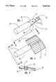
- FIG. 1 is an isometric view of a spar mast employed in the present invention
- FIG. 3 is a cross section of the air foil blade of FIG. 2 taken on line III--III;
- FIG. 4 is a cross section of the air foil blade of FIG. 2 taken on line IV--IV;
- FIG. 5 is a frontal elevation, partially broken away, of a rear stabilizing helicopter turbine with air foil blades embodying the present invention.
- FIG. 6 is an expanded view of a cover and base of an aluminum mold used in the practice of the present invention.
- the present invention relates to air foil blades for use in rear turbine stabilized helicopter aircraft and more particularly to such blades and methods of fabricating such air foil blades from a compounded thermoplastic.
- the air foil blades of the present invention are especially useful, durable and safe when utilized in rear turbine stabilized helicopters.
- each air foil blade be broadly comprises a metal spar 11 and a thermoplastic blade 12.
- a metal spar 11 When employed in a rear stabilized helicopter turbine 13, such air foil blades 1O are used as shown in FIG. 5.
- metal spar 11 consists of a cylindrical body portion 16 and an axially extending flange portion 17 integrally formed therewith generally across a diameter of end surface 18 of body portion 16.
- Flange portion 17 has a proximal (relative to surface 18) segment 19 and a narrower distal segment 20 conjoined by an inwardly tapered transition segment 21.
- a plurality of openings 22 are disposed through flange portion 17 for a purpose to be hereinafter described in detail.
- Blade member 12 comprises a tapered curved aerodynamically figured body portion 24 having a generally rectangular perimeter 25 and disposed about spar 11 and extending through openings 22 to integrally secure blade member 12 to spar 11 and form an integral air foil blade 10.
- Body portion 24 is configured to conform in shape to a computer generated air foil to throw air.
- mold 27 consists of a base member 28 containing a portion of blade cavity 29 and an upper member 30 containing the complementary portion 31 of cavity 29.
- Base member 28 further contains a concave seating means 32 defined in the upper surface 33 thereof to support body portion 16 of spar 11 during the molding cycle.
- Upper member 30 is provided with a concave arch portion 34 disposed in the lower surface 35 thereof and operatively coactive with seating means 32 to provide encircling support for body portion 16 of spar 11 during the molding cycle.
- Metal spar 11 is disposed upon seating means 32 so that flange portion 17 extends into the mold 27 which in turn is mounted into a conventional injection-molding machine (not shown).
- Mold assembly 27 is preferably formed of a light weight metal such as aluminum. Once the mold is filled and cooled, the mold 27 is opened and a finished air foil blade 10 is removed.
- thermo plastic material is injected into the mold to integrally form blade portion 12 to flange portion 17 to form air foil blade 10.
- the thermo plastic of choice is a foamed glass-fiber reinforced polypropylene. This material is preferred because it provides excellent chemical resistance, a replicatable cellular structure which provides consistent weight with each injection, and has a decomposition temperature which closely matches the processing temperature of the foamed polymer thereby insuring consistent good quality for the molded part.
- the glass-fiber reinforced polypropylene material when combined with 1-4% by weight of a foaming agent such as azodicarbonamide will provide an air foil blade having a specific gravity of not more than 1.13 and preferably less than 1.0.
- Glass-fiber reinforced polypropylene materials which have been found suitable for the practice of the present invention include P1-20FG-2100 and P15-FG-0752 (both manufactured by Thermofil, Inc., Brighton, Mich.), and MPP-FG20 and MPP-FG30 (both manufactured by Modified Plastics, Santa Ana, Calif.).
- Foaming agents suitable for use in the practice of the present invention include powdered azodicarbonamide CELOGEN-AZ (available as from Uniroyal, Akron, O) and premixed concentrate containing azodicarbonamide suspended in a suitable carrier (available from THERMOFOAM 1 Thermofil, Inc., Brighton, Mich.).
- thermoplastic compositions when injection molded onto a metal spar weighing between 71 grams and 72 grams, must bring the total maximum weight of the finished air foil up to about 115 grams. Accordingly, the weight of the injected molded plastic blade must not exceed 43 grams to 44 grams.
- a preferred composition for the molding of air foil blades in the practice of the present invention includes a glass fiber filled polypropylene thermoplastic having an optimum temperature for consistent cell structure of less than 450 deg. F admixed with about 1% to 4% by weight of a concentrated azodicarbonamide foaming agent such as THERMOFOAM 1 manufactured by Thermofil, Inc. to achieve from about 5% to about 20% density reduction of the finished polypropylene blade.
- a concentrated azodicarbonamide foaming agent such as THERMOFOAM 1 manufactured by Thermofil, Inc.
- Air foil blades produced using the materials in accordance with and the procedures of the present invention uniform from blade to blade and possess no large voids.
- Each air foil blade is made under controlled conditions so as to eliminate delamination and self destruction in use and each blade obtains substantially identical physical properties, heretofore unattainable with handcrafted blades.
- the present invention enables an integral air foil blade to be formed out of a thermoplastic material which obtains all of the desirable physical properties provided by the hand layup air foil heretofore used while substantially enhancing the reproductability and substantially reducing the unit cost.
- the physical properties obtained by an airfoil blade produced in accordance herewith was 500,000 psi flexural modulus, 650 psi wind shear, low water absorption, excellent chemical resistance while meeting the weight restriction of approximately 44 grams.
- a plurality of air foil blades 10, usually thirteen, are installed into a rear stabilized turbine 13 of a helicopter and extend radially from the central shaft 36 of the turbine 13 in the conventional manner as shown in FIG. 5.
- the air foil blades 10 are controlled, using known technology which need not be described here, to provide pilot control to the pitch of the blades and effect the flow of air and exhaust gases to create a wind shear sufficient to counteract the tendency of the main rotor and keep the cabin from moving rotationally in response thereto.
Landscapes
- Engineering & Computer Science (AREA)
- Mechanical Engineering (AREA)
- General Engineering & Computer Science (AREA)
- Architecture (AREA)
- Wind Motors (AREA)
Abstract
Description
Claims (16)
Priority Applications (1)
| Application Number | Priority Date | Filing Date | Title |
|---|---|---|---|
| US08/180,099 US5403161A (en) | 1991-03-29 | 1994-01-12 | Air foil blade and methods of making same |
Applications Claiming Priority (3)
| Application Number | Priority Date | Filing Date | Title |
|---|---|---|---|
| US67743591A | 1991-03-29 | 1991-03-29 | |
| US98562892A | 1992-12-03 | 1992-12-03 | |
| US08/180,099 US5403161A (en) | 1991-03-29 | 1994-01-12 | Air foil blade and methods of making same |
Related Parent Applications (1)
| Application Number | Title | Priority Date | Filing Date |
|---|---|---|---|
| US98562892A Continuation | 1991-03-29 | 1992-12-03 |
Publications (1)
| Publication Number | Publication Date |
|---|---|
| US5403161A true US5403161A (en) | 1995-04-04 |
Family
ID=27101795
Family Applications (1)
| Application Number | Title | Priority Date | Filing Date |
|---|---|---|---|
| US08/180,099 Expired - Lifetime US5403161A (en) | 1991-03-29 | 1994-01-12 | Air foil blade and methods of making same |
Country Status (1)
| Country | Link |
|---|---|
| US (1) | US5403161A (en) |
Cited By (16)
| Publication number | Priority date | Publication date | Assignee | Title |
|---|---|---|---|---|
| US5527155A (en) * | 1992-08-21 | 1996-06-18 | Mcdonnell Douglas Corp. | Injection molded fan blade |
| WO1998044242A2 (en) * | 1997-03-31 | 1998-10-08 | Horton, Inc. | Integrated fan assembly with variable pitch blades |
| GB2355427A (en) * | 1999-10-22 | 2001-04-25 | Draftex Ind Ltd | An injection moulded ventilation flap and a method of moulding |
| US6253716B1 (en) | 1999-07-07 | 2001-07-03 | Horton, Inc. | Control system for cooling fan assembly having variable pitch blades |
| US20040237521A1 (en) * | 2001-08-03 | 2004-12-02 | Shinjiroh Ohishi | Variable blade manufacturing method and variable blade in vgs type turbo charger |
| US20040250540A1 (en) * | 2001-08-03 | 2004-12-16 | Shinjiroh Ohishi | Variable blade manufacturing method and variable blade in vgs type turbo charger |
| CN101392661A (en) * | 2007-09-20 | 2009-03-25 | 通用电气公司 | Method for making a composite airfoil |
| US20090081032A1 (en) * | 2007-09-20 | 2009-03-26 | General Electric Company | Composite airfoil |
| US20090297356A1 (en) * | 2008-05-30 | 2009-12-03 | General Electric Company | Method of replacing a composite airfoil |
| US7901189B2 (en) | 2007-05-14 | 2011-03-08 | General Electric Company | Wind-turbine blade and method for reducing noise in wind turbine |
| US8876483B2 (en) | 2010-01-14 | 2014-11-04 | Neptco, Inc. | Wind turbine rotor blade components and methods of making same |
| WO2014130131A3 (en) * | 2012-12-10 | 2014-11-27 | General Electric Company | Attachment of composite article |
| CN105298913A (en) * | 2015-11-27 | 2016-02-03 | 卧龙电气南阳防爆集团股份有限公司 | Blade of axial flow fan and manufacturing method of blade |
| US20160167269A1 (en) * | 2013-07-29 | 2016-06-16 | Safran | Method of fabricating a composite material blade having an integrated metal leading edge for a gas turbine aeroengine |
| US9777579B2 (en) | 2012-12-10 | 2017-10-03 | General Electric Company | Attachment of composite article |
| US10137542B2 (en) | 2010-01-14 | 2018-11-27 | Senvion Gmbh | Wind turbine rotor blade components and machine for making same |
Citations (8)
| Publication number | Priority date | Publication date | Assignee | Title |
|---|---|---|---|---|
| FR901587A (en) * | 1943-02-26 | 1945-07-31 | Augsburg Nu Rnberg Ag Maschf | Blade for fluid circulation machines, in particular for axial compressors |
| US2423700A (en) * | 1943-06-16 | 1947-07-08 | Marquette Metal Products Co | Propeller blade |
| FR1355427A (en) * | 1963-05-10 | 1964-03-13 | Neu Sa | Improvement in axial fans |
| US3305196A (en) * | 1964-11-04 | 1967-02-21 | Dow Chemical Co | Vehicular structures made from foamed plastic materials |
| SU808685A1 (en) * | 1977-05-26 | 1981-02-28 | Предприятие П/Я А-3513 | Hydraulic machine impeller blade |
| US4477228A (en) * | 1982-01-28 | 1984-10-16 | The Boeing Company | Injection molded propeller |
| JPS61215498A (en) * | 1985-03-22 | 1986-09-25 | Nippon Radiator Co Ltd | Air supply fan |
| US5076760A (en) * | 1990-11-01 | 1991-12-31 | General Signal Corporation | Injection molded, high strength impeller |
-
1994
- 1994-01-12 US US08/180,099 patent/US5403161A/en not_active Expired - Lifetime
Patent Citations (8)
| Publication number | Priority date | Publication date | Assignee | Title |
|---|---|---|---|---|
| FR901587A (en) * | 1943-02-26 | 1945-07-31 | Augsburg Nu Rnberg Ag Maschf | Blade for fluid circulation machines, in particular for axial compressors |
| US2423700A (en) * | 1943-06-16 | 1947-07-08 | Marquette Metal Products Co | Propeller blade |
| FR1355427A (en) * | 1963-05-10 | 1964-03-13 | Neu Sa | Improvement in axial fans |
| US3305196A (en) * | 1964-11-04 | 1967-02-21 | Dow Chemical Co | Vehicular structures made from foamed plastic materials |
| SU808685A1 (en) * | 1977-05-26 | 1981-02-28 | Предприятие П/Я А-3513 | Hydraulic machine impeller blade |
| US4477228A (en) * | 1982-01-28 | 1984-10-16 | The Boeing Company | Injection molded propeller |
| JPS61215498A (en) * | 1985-03-22 | 1986-09-25 | Nippon Radiator Co Ltd | Air supply fan |
| US5076760A (en) * | 1990-11-01 | 1991-12-31 | General Signal Corporation | Injection molded, high strength impeller |
Cited By (32)
| Publication number | Priority date | Publication date | Assignee | Title |
|---|---|---|---|---|
| US5527155A (en) * | 1992-08-21 | 1996-06-18 | Mcdonnell Douglas Corp. | Injection molded fan blade |
| US5691391A (en) * | 1992-08-21 | 1997-11-25 | Mcdonnell Douglas Helicopter | Process for making an injection molded fan blade |
| WO1998044242A2 (en) * | 1997-03-31 | 1998-10-08 | Horton, Inc. | Integrated fan assembly with variable pitch blades |
| WO1998044242A3 (en) * | 1997-03-31 | 1998-12-30 | Horton Inc | Integrated fan assembly with variable pitch blades |
| US6109871A (en) * | 1997-03-31 | 2000-08-29 | Horton, Inc. | Integrated fan assembly with variable pitch blades |
| US6253716B1 (en) | 1999-07-07 | 2001-07-03 | Horton, Inc. | Control system for cooling fan assembly having variable pitch blades |
| GB2355427A (en) * | 1999-10-22 | 2001-04-25 | Draftex Ind Ltd | An injection moulded ventilation flap and a method of moulding |
| GB2355427B (en) * | 1999-10-22 | 2004-03-17 | Draftex Ind Ltd | Moulding a ventilation flap |
| US20040237521A1 (en) * | 2001-08-03 | 2004-12-02 | Shinjiroh Ohishi | Variable blade manufacturing method and variable blade in vgs type turbo charger |
| US20040250540A1 (en) * | 2001-08-03 | 2004-12-16 | Shinjiroh Ohishi | Variable blade manufacturing method and variable blade in vgs type turbo charger |
| US7089664B2 (en) * | 2001-08-03 | 2006-08-15 | Akita Fine Blanking Co., Ltd. | Variable blade manufacturing method and variable blade in VGS type turbo charger |
| US7117596B2 (en) * | 2001-08-03 | 2006-10-10 | Akita Fine Blanking Co., Ltd. | Variable blade manufacturing method and variable blade in VGS type turbo charger |
| US7901189B2 (en) | 2007-05-14 | 2011-03-08 | General Electric Company | Wind-turbine blade and method for reducing noise in wind turbine |
| CN101392661A (en) * | 2007-09-20 | 2009-03-25 | 通用电气公司 | Method for making a composite airfoil |
| US20090077802A1 (en) * | 2007-09-20 | 2009-03-26 | General Electric Company | Method for making a composite airfoil |
| US20090081032A1 (en) * | 2007-09-20 | 2009-03-26 | General Electric Company | Composite airfoil |
| FR2931719A1 (en) * | 2008-05-30 | 2009-12-04 | Gen Electric | PROCESS FOR REPLACING A COMPOSITE PROFILE |
| US8146250B2 (en) * | 2008-05-30 | 2012-04-03 | General Electric Company | Method of replacing a composite airfoil |
| US20090297356A1 (en) * | 2008-05-30 | 2009-12-03 | General Electric Company | Method of replacing a composite airfoil |
| US9394882B2 (en) | 2010-01-14 | 2016-07-19 | Senvion Gmbh | Wind turbine rotor blade components and methods of making same |
| US8876483B2 (en) | 2010-01-14 | 2014-11-04 | Neptco, Inc. | Wind turbine rotor blade components and methods of making same |
| US10137542B2 (en) | 2010-01-14 | 2018-11-27 | Senvion Gmbh | Wind turbine rotor blade components and machine for making same |
| US9945355B2 (en) | 2010-01-14 | 2018-04-17 | Senvion Gmbh | Wind turbine rotor blade components and methods of making same |
| US9429140B2 (en) | 2010-01-14 | 2016-08-30 | Senvion Gmbh | Wind turbine rotor blade components and methods of making same |
| CN104838091B (en) * | 2012-12-10 | 2016-12-07 | 通用电气公司 | The adnexa of composite product |
| US9777579B2 (en) | 2012-12-10 | 2017-10-03 | General Electric Company | Attachment of composite article |
| US9797257B2 (en) | 2012-12-10 | 2017-10-24 | General Electric Company | Attachment of composite article |
| CN104838091A (en) * | 2012-12-10 | 2015-08-12 | 通用电气公司 | Attachment of composite article |
| WO2014130131A3 (en) * | 2012-12-10 | 2014-11-27 | General Electric Company | Attachment of composite article |
| US20160167269A1 (en) * | 2013-07-29 | 2016-06-16 | Safran | Method of fabricating a composite material blade having an integrated metal leading edge for a gas turbine aeroengine |
| US10899051B2 (en) * | 2013-07-29 | 2021-01-26 | Safran | Method of fabricating a composite material blade having an integrated metal leading edge for a gas turbine aeroengine |
| CN105298913A (en) * | 2015-11-27 | 2016-02-03 | 卧龙电气南阳防爆集团股份有限公司 | Blade of axial flow fan and manufacturing method of blade |
Similar Documents
| Publication | Publication Date | Title |
|---|---|---|
| US5403161A (en) | Air foil blade and methods of making same | |
| US9266603B2 (en) | Single-piece propeller and method of making | |
| US5707723A (en) | Multilayer radome structure and its fabrication | |
| US5222297A (en) | Composite blade manufacture | |
| US4405543A (en) | Materials suitable for thermosetting | |
| US5439353A (en) | Composite blade with reinforced leading edge | |
| US5605440A (en) | Flow-straightener vane made of composite, flow-straightener including it, for a counter-torque device with ducted rotor and ducted flow-straightening stator, and method for manufacturing them | |
| US5346367A (en) | Advanced composite rotor blade | |
| US2484141A (en) | Skin stressed laminated fiberglas rotor blade | |
| US4086378A (en) | Stiffened composite structural member and method of fabrication | |
| EP1136353B1 (en) | Composite spinner and method of making the same | |
| US6056838A (en) | Method for manufacturing a variable-pitch composite blade for a helicopter rotor | |
| EP0292086B1 (en) | Fan blade for an axial flow fan and method of forming same | |
| US3237697A (en) | Helicopter rotor blade | |
| ES2545074T5 (en) | Manufacturing process for a rotor blade of a wind turbine | |
| US20110194941A1 (en) | Co-cured sheath for composite blade | |
| US6231941B1 (en) | Radius fillers for a resin transfer molding process | |
| US2908943A (en) | Process for molding two-layer polyurethane articles | |
| JPH06508078A (en) | Complex textile composite parts and their manufacturing methods | |
| KR101175953B1 (en) | a manufacturing method of FRP products, and FRP products | |
| US4477228A (en) | Injection molded propeller | |
| US5691391A (en) | Process for making an injection molded fan blade | |
| US5091029A (en) | Method of manufacturing a unitary, multi-legged helicopter rotor flexbeam made solely of composite materials | |
| CN108839398B (en) | Propeller with carbon fiber-porous nylon composite structure and preparation method thereof | |
| RU2688603C1 (en) | Blade and method of its production |
Legal Events
| Date | Code | Title | Description |
|---|---|---|---|
| STCF | Information on status: patent grant |
Free format text: PATENTED CASE |
|
| FEPP | Fee payment procedure |
Free format text: PAYOR NUMBER ASSIGNED (ORIGINAL EVENT CODE: ASPN); ENTITY STATUS OF PATENT OWNER: LARGE ENTITY Free format text: PAT HLDR NO LONGER CLAIMS SMALL ENT STAT AS SMALL BUSINESS (ORIGINAL EVENT CODE: LSM2); ENTITY STATUS OF PATENT OWNER: LARGE ENTITY |
|
| AS | Assignment |
Owner name: MCDONNELL DOUGLAS HELICOPTER COMPANY D/B/A MCDONNE Free format text: ASSIGNMENT OF ASSIGNORS INTEREST;ASSIGNOR:NEALON, DENNIS T.;REEL/FRAME:009328/0279 Effective date: 19980710 |
|
| FPAY | Fee payment |
Year of fee payment: 4 |
|
| FPAY | Fee payment |
Year of fee payment: 8 |
|
| REMI | Maintenance fee reminder mailed | ||
| FPAY | Fee payment |
Year of fee payment: 12 |