US5401606A - Laser-induced melt transfer process - Google Patents
Laser-induced melt transfer process Download PDFInfo
- Publication number
- US5401606A US5401606A US08/103,302 US10330293A US5401606A US 5401606 A US5401606 A US 5401606A US 10330293 A US10330293 A US 10330293A US 5401606 A US5401606 A US 5401606A
- Authority
- US
- United States
- Prior art keywords
- laser
- melt viscosity
- colorant
- mvm
- receiver element
- Prior art date
- Legal status (The legal status is an assumption and is not a legal conclusion. Google has not performed a legal analysis and makes no representation as to the accuracy of the status listed.)
- Expired - Lifetime
Links
- 238000000034 method Methods 0.000 title claims abstract description 31
- 239000004034 viscosity adjusting agent Substances 0.000 claims abstract description 11
- 239000003086 colorant Substances 0.000 claims description 22
- 239000000203 mixture Substances 0.000 claims description 21
- 230000005855 radiation Effects 0.000 claims description 13
- 239000011230 binding agent Substances 0.000 claims description 12
- 239000000155 melt Substances 0.000 abstract description 7
- 238000000576 coating method Methods 0.000 description 41
- 239000011248 coating agent Substances 0.000 description 40
- 239000010410 layer Substances 0.000 description 30
- 239000000463 material Substances 0.000 description 26
- 239000000975 dye Substances 0.000 description 25
- 239000000049 pigment Substances 0.000 description 23
- IISBACLAFKSPIT-UHFFFAOYSA-N bisphenol A Chemical compound C=1C=C(O)C=CC=1C(C)(C)C1=CC=C(O)C=C1 IISBACLAFKSPIT-UHFFFAOYSA-N 0.000 description 10
- -1 polyethylene terephthalate Polymers 0.000 description 10
- ZWEHNKRNPOVVGH-UHFFFAOYSA-N 2-Butanone Chemical compound CCC(C)=O ZWEHNKRNPOVVGH-UHFFFAOYSA-N 0.000 description 9
- DOIRQSBPFJWKBE-UHFFFAOYSA-N dibutyl phthalate Chemical compound CCCCOC(=O)C1=CC=CC=C1C(=O)OCCCC DOIRQSBPFJWKBE-UHFFFAOYSA-N 0.000 description 9
- 238000003384 imaging method Methods 0.000 description 9
- 229910052782 aluminium Inorganic materials 0.000 description 8
- XAGFODPZIPBFFR-UHFFFAOYSA-N aluminium Chemical compound [Al] XAGFODPZIPBFFR-UHFFFAOYSA-N 0.000 description 8
- 239000002270 dispersing agent Substances 0.000 description 8
- 238000009472 formulation Methods 0.000 description 7
- 239000007787 solid Substances 0.000 description 7
- 239000002904 solvent Substances 0.000 description 7
- HMBNQNDUEFFFNZ-UHFFFAOYSA-N 4-ethenoxybutan-1-ol Chemical compound OCCCCOC=C HMBNQNDUEFFFNZ-UHFFFAOYSA-N 0.000 description 6
- 229920000728 polyester Polymers 0.000 description 6
- DQNSRQYYCSXZDF-UHFFFAOYSA-N 1,4-bis(ethenoxymethyl)cyclohexane Chemical compound C=COCC1CCC(COC=C)CC1 DQNSRQYYCSXZDF-UHFFFAOYSA-N 0.000 description 5
- 239000003822 epoxy resin Substances 0.000 description 5
- 229920000647 polyepoxide Polymers 0.000 description 5
- 238000007639 printing Methods 0.000 description 5
- YSUQLAYJZDEMOT-UHFFFAOYSA-N 2-(butoxymethyl)oxirane Chemical compound CCCCOCC1CO1 YSUQLAYJZDEMOT-UHFFFAOYSA-N 0.000 description 4
- 239000008199 coating composition Substances 0.000 description 4
- 229910052751 metal Inorganic materials 0.000 description 4
- 239000002184 metal Substances 0.000 description 4
- 229920000139 polyethylene terephthalate Polymers 0.000 description 4
- 239000005020 polyethylene terephthalate Substances 0.000 description 4
- 229920005989 resin Polymers 0.000 description 4
- 239000011347 resin Substances 0.000 description 4
- 239000000523 sample Substances 0.000 description 4
- CERQOIWHTDAKMF-UHFFFAOYSA-M Methacrylate Chemical compound CC(=C)C([O-])=O CERQOIWHTDAKMF-UHFFFAOYSA-M 0.000 description 3
- XCJYREBRNVKWGJ-UHFFFAOYSA-N copper(II) phthalocyanine Chemical compound [Cu+2].C12=CC=CC=C2C(N=C2[N-]C(C3=CC=CC=C32)=N2)=NC1=NC([C]1C=CC=CC1=1)=NC=1N=C1[C]3C=CC=CC3=C2[N-]1 XCJYREBRNVKWGJ-UHFFFAOYSA-N 0.000 description 3
- 230000000694 effects Effects 0.000 description 3
- 229920003986 novolac Polymers 0.000 description 3
- 239000002245 particle Substances 0.000 description 3
- 229920000642 polymer Polymers 0.000 description 3
- 229920000098 polyolefin Polymers 0.000 description 3
- 239000000243 solution Substances 0.000 description 3
- 229920002799 BoPET Polymers 0.000 description 2
- OKTJSMMVPCPJKN-UHFFFAOYSA-N Carbon Chemical compound [C] OKTJSMMVPCPJKN-UHFFFAOYSA-N 0.000 description 2
- 239000004593 Epoxy Substances 0.000 description 2
- PEDCQBHIVMGVHV-UHFFFAOYSA-N Glycerine Chemical compound OCC(O)CO PEDCQBHIVMGVHV-UHFFFAOYSA-N 0.000 description 2
- HIZCTWCPHWUPFU-UHFFFAOYSA-N Glycerol tribenzoate Chemical compound C=1C=CC=CC=1C(=O)OCC(OC(=O)C=1C=CC=CC=1)COC(=O)C1=CC=CC=C1 HIZCTWCPHWUPFU-UHFFFAOYSA-N 0.000 description 2
- PPBRXRYQALVLMV-UHFFFAOYSA-N Styrene Chemical compound C=CC1=CC=CC=C1 PPBRXRYQALVLMV-UHFFFAOYSA-N 0.000 description 2
- GWEVSGVZZGPLCZ-UHFFFAOYSA-N Titan oxide Chemical compound O=[Ti]=O GWEVSGVZZGPLCZ-UHFFFAOYSA-N 0.000 description 2
- 230000002411 adverse Effects 0.000 description 2
- 150000001298 alcohols Chemical class 0.000 description 2
- DKPFZGUDAPQIHT-UHFFFAOYSA-N butyl acetate Chemical compound CCCCOC(C)=O DKPFZGUDAPQIHT-UHFFFAOYSA-N 0.000 description 2
- 239000006229 carbon black Substances 0.000 description 2
- VDQQXEISLMTGAB-UHFFFAOYSA-N chloramine T Chemical compound [Na+].CC1=CC=C(S(=O)(=O)[N-]Cl)C=C1 VDQQXEISLMTGAB-UHFFFAOYSA-N 0.000 description 2
- 229920001577 copolymer Polymers 0.000 description 2
- 239000006185 dispersion Substances 0.000 description 2
- VOZRXNHHFUQHIL-UHFFFAOYSA-N glycidyl methacrylate Chemical compound CC(=C)C(=O)OCC1CO1 VOZRXNHHFUQHIL-UHFFFAOYSA-N 0.000 description 2
- 239000010439 graphite Substances 0.000 description 2
- 229910002804 graphite Inorganic materials 0.000 description 2
- 239000004615 ingredient Substances 0.000 description 2
- 239000001023 inorganic pigment Substances 0.000 description 2
- 239000000178 monomer Substances 0.000 description 2
- 230000003287 optical effect Effects 0.000 description 2
- IEQIEDJGQAUEQZ-UHFFFAOYSA-N phthalocyanine Chemical class N1C(N=C2C3=CC=CC=C3C(N=C3C4=CC=CC=C4C(=N4)N3)=N2)=C(C=CC=C2)C2=C1N=C1C2=CC=CC=C2C4=N1 IEQIEDJGQAUEQZ-UHFFFAOYSA-N 0.000 description 2
- 239000004014 plasticizer Substances 0.000 description 2
- 229920003229 poly(methyl methacrylate) Polymers 0.000 description 2
- 229920000058 polyacrylate Polymers 0.000 description 2
- 239000004417 polycarbonate Substances 0.000 description 2
- 229920000515 polycarbonate Polymers 0.000 description 2
- 239000004926 polymethyl methacrylate Substances 0.000 description 2
- 229920002635 polyurethane Polymers 0.000 description 2
- 239000004814 polyurethane Substances 0.000 description 2
- 238000002360 preparation method Methods 0.000 description 2
- 238000000926 separation method Methods 0.000 description 2
- 238000000859 sublimation Methods 0.000 description 2
- 230000008022 sublimation Effects 0.000 description 2
- 239000004094 surface-active agent Substances 0.000 description 2
- 229920001897 terpolymer Polymers 0.000 description 2
- 125000000391 vinyl group Chemical group [H]C([*])=C([H])[H] 0.000 description 2
- 239000001993 wax Substances 0.000 description 2
- CYIGRWUIQAVBFG-UHFFFAOYSA-N 1,2-bis(2-ethenoxyethoxy)ethane Chemical compound C=COCCOCCOCCOC=C CYIGRWUIQAVBFG-UHFFFAOYSA-N 0.000 description 1
- TXWSZJSDZKWQAU-UHFFFAOYSA-N 2,9-dimethyl-5,12-dihydroquinolino[2,3-b]acridine-7,14-dione Chemical compound N1C2=CC=C(C)C=C2C(=O)C2=C1C=C(C(=O)C=1C(=CC=C(C=1)C)N1)C1=C2 TXWSZJSDZKWQAU-UHFFFAOYSA-N 0.000 description 1
- KUBDPQJOLOUJRM-UHFFFAOYSA-N 2-(chloromethyl)oxirane;4-[2-(4-hydroxyphenyl)propan-2-yl]phenol Chemical compound ClCC1CO1.C=1C=C(O)C=CC=1C(C)(C)C1=CC=C(O)C=C1 KUBDPQJOLOUJRM-UHFFFAOYSA-N 0.000 description 1
- LXBGSDVWAMZHDD-UHFFFAOYSA-N 2-methyl-1h-imidazole Chemical compound CC1=NC=CN1 LXBGSDVWAMZHDD-UHFFFAOYSA-N 0.000 description 1
- WRAHUJZNRDEANF-UHFFFAOYSA-M 3-methyl-2,6-bis(3-methylpentan-3-yl)thiopyrylium hydroxide Chemical compound [OH-].CCC(C)(CC)c1ccc(C)c([s+]1)C(C)(CC)CC WRAHUJZNRDEANF-UHFFFAOYSA-M 0.000 description 1
- RKJUIXBNRJVNHR-UHFFFAOYSA-N 3H-indole Chemical compound C1=CC=C2CC=NC2=C1 RKJUIXBNRJVNHR-UHFFFAOYSA-N 0.000 description 1
- 229920003319 Araldite® Polymers 0.000 description 1
- VEXZGXHMUGYJMC-UHFFFAOYSA-M Chloride anion Chemical compound [Cl-] VEXZGXHMUGYJMC-UHFFFAOYSA-M 0.000 description 1
- RYGMFSIKBFXOCR-UHFFFAOYSA-N Copper Chemical compound [Cu] RYGMFSIKBFXOCR-UHFFFAOYSA-N 0.000 description 1
- VVQNEPGJFQJSBK-UHFFFAOYSA-N Methyl methacrylate Chemical compound COC(=O)C(C)=C VVQNEPGJFQJSBK-UHFFFAOYSA-N 0.000 description 1
- 239000004952 Polyamide Substances 0.000 description 1
- 239000004695 Polyether sulfone Substances 0.000 description 1
- 239000004698 Polyethylene Substances 0.000 description 1
- 239000004642 Polyimide Substances 0.000 description 1
- 229910000831 Steel Inorganic materials 0.000 description 1
- 229920000690 Tyvek Polymers 0.000 description 1
- 239000004775 Tyvek Substances 0.000 description 1
- QYKIQEUNHZKYBP-UHFFFAOYSA-N Vinyl ether Chemical class C=COC=C QYKIQEUNHZKYBP-UHFFFAOYSA-N 0.000 description 1
- HCHKCACWOHOZIP-UHFFFAOYSA-N Zinc Chemical compound [Zn] HCHKCACWOHOZIP-UHFFFAOYSA-N 0.000 description 1
- 239000011358 absorbing material Substances 0.000 description 1
- 238000010521 absorption reaction Methods 0.000 description 1
- 150000001242 acetic acid derivatives Chemical class 0.000 description 1
- 239000002253 acid Substances 0.000 description 1
- 150000001252 acrylic acid derivatives Chemical class 0.000 description 1
- NIXOWILDQLNWCW-UHFFFAOYSA-N acrylic acid group Chemical group C(C=C)(=O)O NIXOWILDQLNWCW-UHFFFAOYSA-N 0.000 description 1
- 239000000654 additive Substances 0.000 description 1
- 235000011037 adipic acid Nutrition 0.000 description 1
- 150000001279 adipic acids Chemical class 0.000 description 1
- 238000005054 agglomeration Methods 0.000 description 1
- 230000002776 aggregation Effects 0.000 description 1
- 229920003235 aromatic polyamide Polymers 0.000 description 1
- 150000001541 aziridines Chemical class 0.000 description 1
- 238000000498 ball milling Methods 0.000 description 1
- 230000009286 beneficial effect Effects 0.000 description 1
- 235000010233 benzoic acid Nutrition 0.000 description 1
- 150000001559 benzoic acids Chemical class 0.000 description 1
- 230000015572 biosynthetic process Effects 0.000 description 1
- 239000004841 bisphenol A epoxy resin Substances 0.000 description 1
- 239000001055 blue pigment Substances 0.000 description 1
- 229920002678 cellulose Polymers 0.000 description 1
- 229920002301 cellulose acetate Polymers 0.000 description 1
- 239000003795 chemical substances by application Substances 0.000 description 1
- 150000001875 compounds Chemical class 0.000 description 1
- 239000013068 control sample Substances 0.000 description 1
- 229910052802 copper Inorganic materials 0.000 description 1
- 239000010949 copper Substances 0.000 description 1
- 230000007423 decrease Effects 0.000 description 1
- MTHSVFCYNBDYFN-UHFFFAOYSA-N diethylene glycol Chemical compound OCCOCCO MTHSVFCYNBDYFN-UHFFFAOYSA-N 0.000 description 1
- 150000002118 epoxides Chemical class 0.000 description 1
- 125000000219 ethylidene group Chemical group [H]C(=[*])C([H])([H])[H] 0.000 description 1
- 238000005189 flocculation Methods 0.000 description 1
- 230000016615 flocculation Effects 0.000 description 1
- 229920002313 fluoropolymer Polymers 0.000 description 1
- 239000004811 fluoropolymer Substances 0.000 description 1
- 239000011521 glass Substances 0.000 description 1
- 235000011187 glycerol Nutrition 0.000 description 1
- 238000007646 gravure printing Methods 0.000 description 1
- LNEPOXFFQSENCJ-UHFFFAOYSA-N haloperidol Chemical compound C1CC(O)(C=2C=CC(Cl)=CC=2)CCN1CCCC(=O)C1=CC=C(F)C=C1 LNEPOXFFQSENCJ-UHFFFAOYSA-N 0.000 description 1
- 239000006099 infrared radiation absorber Substances 0.000 description 1
- 238000007689 inspection Methods 0.000 description 1
- 239000004850 liquid epoxy resins (LERs) Substances 0.000 description 1
- 238000001459 lithography Methods 0.000 description 1
- 238000011068 loading method Methods 0.000 description 1
- DZVCFNFOPIZQKX-LTHRDKTGSA-M merocyanine Chemical compound [Na+].O=C1N(CCCC)C(=O)N(CCCC)C(=O)C1=C\C=C\C=C/1N(CCCS([O-])(=O)=O)C2=CC=CC=C2O\1 DZVCFNFOPIZQKX-LTHRDKTGSA-M 0.000 description 1
- 150000002734 metacrylic acid derivatives Chemical class 0.000 description 1
- 150000002739 metals Chemical class 0.000 description 1
- 125000005395 methacrylic acid group Chemical class 0.000 description 1
- 125000002496 methyl group Chemical group [H]C([H])([H])* 0.000 description 1
- 238000003801 milling Methods 0.000 description 1
- 239000011259 mixed solution Substances 0.000 description 1
- 238000002156 mixing Methods 0.000 description 1
- 239000003607 modifier Substances 0.000 description 1
- 239000012860 organic pigment Substances 0.000 description 1
- 229920000620 organic polymer Polymers 0.000 description 1
- 150000002989 phenols Chemical class 0.000 description 1
- 150000003022 phthalic acids Chemical class 0.000 description 1
- 229920002647 polyamide Polymers 0.000 description 1
- 229920001610 polycaprolactone Polymers 0.000 description 1
- 229920006267 polyester film Polymers 0.000 description 1
- 229920006393 polyether sulfone Polymers 0.000 description 1
- 229920000573 polyethylene Polymers 0.000 description 1
- 229920001721 polyimide Polymers 0.000 description 1
- 229920006324 polyoxymethylene Polymers 0.000 description 1
- 150000003839 salts Chemical class 0.000 description 1
- 239000004576 sand Substances 0.000 description 1
- 239000004065 semiconductor Substances 0.000 description 1
- 239000002356 single layer Substances 0.000 description 1
- 238000001228 spectrum Methods 0.000 description 1
- 239000010959 steel Substances 0.000 description 1
- 239000000126 substance Substances 0.000 description 1
- 239000000758 substrate Substances 0.000 description 1
- 238000001931 thermography Methods 0.000 description 1
- 150000007944 thiolates Chemical class 0.000 description 1
- ANRHNWWPFJCPAZ-UHFFFAOYSA-M thionine Chemical compound [Cl-].C1=CC(N)=CC2=[S+]C3=CC(N)=CC=C3N=C21 ANRHNWWPFJCPAZ-UHFFFAOYSA-M 0.000 description 1
- 239000004408 titanium dioxide Substances 0.000 description 1
- 238000011282 treatment Methods 0.000 description 1
- 229920002554 vinyl polymer Polymers 0.000 description 1
- 238000009736 wetting Methods 0.000 description 1
- 239000012463 white pigment Substances 0.000 description 1
- 239000011701 zinc Substances 0.000 description 1
- 229910052725 zinc Inorganic materials 0.000 description 1
Images

Classifications
-
- B—PERFORMING OPERATIONS; TRANSPORTING
- B41—PRINTING; LINING MACHINES; TYPEWRITERS; STAMPS
- B41M—PRINTING, DUPLICATING, MARKING, OR COPYING PROCESSES; COLOUR PRINTING
- B41M5/00—Duplicating or marking methods; Sheet materials for use therein
- B41M5/26—Thermography ; Marking by high energetic means, e.g. laser otherwise than by burning, and characterised by the material used
- B41M5/40—Thermography ; Marking by high energetic means, e.g. laser otherwise than by burning, and characterised by the material used characterised by the base backcoat, intermediate, or covering layers, e.g. for thermal transfer dye-donor or dye-receiver sheets; Heat, radiation filtering or absorbing means or layers; combined with other image registration layers or compositions; Special originals for reproduction by thermography
- B41M5/42—Intermediate, backcoat, or covering layers
- B41M5/423—Intermediate, backcoat, or covering layers characterised by non-macromolecular compounds, e.g. waxes
-
- B—PERFORMING OPERATIONS; TRANSPORTING
- B41—PRINTING; LINING MACHINES; TYPEWRITERS; STAMPS
- B41C—PROCESSES FOR THE MANUFACTURE OR REPRODUCTION OF PRINTING SURFACES
- B41C1/00—Forme preparation
- B41C1/10—Forme preparation for lithographic printing; Master sheets for transferring a lithographic image to the forme
- B41C1/1091—Forme preparation for lithographic printing; Master sheets for transferring a lithographic image to the forme by physical transfer from a donor sheet having an uniform coating of lithographic material using thermal means as provided by a thermal head or a laser; by mechanical pressure, e.g. from a typewriter by electrical recording ribbon therefor
-
- B—PERFORMING OPERATIONS; TRANSPORTING
- B41—PRINTING; LINING MACHINES; TYPEWRITERS; STAMPS
- B41M—PRINTING, DUPLICATING, MARKING, OR COPYING PROCESSES; COLOUR PRINTING
- B41M5/00—Duplicating or marking methods; Sheet materials for use therein
- B41M5/26—Thermography ; Marking by high energetic means, e.g. laser otherwise than by burning, and characterised by the material used
- B41M5/382—Contact thermal transfer or sublimation processes
- B41M5/392—Additives, other than colour forming substances, dyes or pigments, e.g. sensitisers, transfer promoting agents
-
- B—PERFORMING OPERATIONS; TRANSPORTING
- B41—PRINTING; LINING MACHINES; TYPEWRITERS; STAMPS
- B41M—PRINTING, DUPLICATING, MARKING, OR COPYING PROCESSES; COLOUR PRINTING
- B41M5/00—Duplicating or marking methods; Sheet materials for use therein
- B41M5/26—Thermography ; Marking by high energetic means, e.g. laser otherwise than by burning, and characterised by the material used
- B41M5/40—Thermography ; Marking by high energetic means, e.g. laser otherwise than by burning, and characterised by the material used characterised by the base backcoat, intermediate, or covering layers, e.g. for thermal transfer dye-donor or dye-receiver sheets; Heat, radiation filtering or absorbing means or layers; combined with other image registration layers or compositions; Special originals for reproduction by thermography
- B41M5/46—Thermography ; Marking by high energetic means, e.g. laser otherwise than by burning, and characterised by the material used characterised by the base backcoat, intermediate, or covering layers, e.g. for thermal transfer dye-donor or dye-receiver sheets; Heat, radiation filtering or absorbing means or layers; combined with other image registration layers or compositions; Special originals for reproduction by thermography characterised by the light-to-heat converting means; characterised by the heat or radiation filtering or absorbing means or layers
-
- B—PERFORMING OPERATIONS; TRANSPORTING
- B41—PRINTING; LINING MACHINES; TYPEWRITERS; STAMPS
- B41M—PRINTING, DUPLICATING, MARKING, OR COPYING PROCESSES; COLOUR PRINTING
- B41M2205/00—Printing methods or features related to printing methods; Location or type of the layers
- B41M2205/06—Printing methods or features related to printing methods; Location or type of the layers relating to melt (thermal) mass transfer
-
- B—PERFORMING OPERATIONS; TRANSPORTING
- B41—PRINTING; LINING MACHINES; TYPEWRITERS; STAMPS
- B41M—PRINTING, DUPLICATING, MARKING, OR COPYING PROCESSES; COLOUR PRINTING
- B41M5/00—Duplicating or marking methods; Sheet materials for use therein
- B41M5/26—Thermography ; Marking by high energetic means, e.g. laser otherwise than by burning, and characterised by the material used
- B41M5/40—Thermography ; Marking by high energetic means, e.g. laser otherwise than by burning, and characterised by the material used characterised by the base backcoat, intermediate, or covering layers, e.g. for thermal transfer dye-donor or dye-receiver sheets; Heat, radiation filtering or absorbing means or layers; combined with other image registration layers or compositions; Special originals for reproduction by thermography
- B41M5/46—Thermography ; Marking by high energetic means, e.g. laser otherwise than by burning, and characterised by the material used characterised by the base backcoat, intermediate, or covering layers, e.g. for thermal transfer dye-donor or dye-receiver sheets; Heat, radiation filtering or absorbing means or layers; combined with other image registration layers or compositions; Special originals for reproduction by thermography characterised by the light-to-heat converting means; characterised by the heat or radiation filtering or absorbing means or layers
- B41M5/465—Infrared radiation-absorbing materials, e.g. dyes, metals, silicates, C black
-
- Y—GENERAL TAGGING OF NEW TECHNOLOGICAL DEVELOPMENTS; GENERAL TAGGING OF CROSS-SECTIONAL TECHNOLOGIES SPANNING OVER SEVERAL SECTIONS OF THE IPC; TECHNICAL SUBJECTS COVERED BY FORMER USPC CROSS-REFERENCE ART COLLECTIONS [XRACs] AND DIGESTS
- Y10—TECHNICAL SUBJECTS COVERED BY FORMER USPC
- Y10S—TECHNICAL SUBJECTS COVERED BY FORMER USPC CROSS-REFERENCE ART COLLECTIONS [XRACs] AND DIGESTS
- Y10S430/00—Radiation imagery chemistry: process, composition, or product thereof
- Y10S430/153—Multiple image producing on single receiver
-
- Y—GENERAL TAGGING OF NEW TECHNOLOGICAL DEVELOPMENTS; GENERAL TAGGING OF CROSS-SECTIONAL TECHNOLOGIES SPANNING OVER SEVERAL SECTIONS OF THE IPC; TECHNICAL SUBJECTS COVERED BY FORMER USPC CROSS-REFERENCE ART COLLECTIONS [XRACs] AND DIGESTS
- Y10—TECHNICAL SUBJECTS COVERED BY FORMER USPC
- Y10S—TECHNICAL SUBJECTS COVERED BY FORMER USPC CROSS-REFERENCE ART COLLECTIONS [XRACs] AND DIGESTS
- Y10S430/00—Radiation imagery chemistry: process, composition, or product thereof
- Y10S430/165—Thermal imaging composition
Definitions
- This invention relates to a thermal transfer process and, in particular, to a laser-induced melt transfer process.
- Laser-induced thermal transfer processes are well-known in applications such as color proofing and lithography. Such laser-induced processes include, for example, dye sublimation, dye transfer, ablative material transfer, and melt transfer of fusible materials such as waxes. Such processes are described in, for example, Baldock, UK Patent 2,083,726; DeBoer, U.S. Pat. No. 4,942,141; Kellogg, U.S. Pat. No. 5,019,549; Evans, U.S. Pat. No. 4,948,776; Foley et al., U.S. Pat. No. 5,156,938; Ellis et al., U.S. Pat. No. 5,171,650; and Koshizuka et al., U.S.
- the processes use a laserable assemblage comprising a donor element that contains the imageable component, i.e., the material to be transferred, and a receiver element.
- the donor element is imagewise exposed by a laser, usually an infrared laser, resulting in transfer of material to the receiver element.
- the exposure takes place only in a small, selected region of the donor at one time, so that the transfer can be built up one pixel at a time.
- Computer control produces transfer with high resolution and at high speed.
- the imageable component is a colorant.
- the imageable component is an oleophilic material which will receive and transfer ink in printing.
- a separate infrared radiation absorber is also included.
- Dyes used in dye sublimation and dye transfer processes are frequently unstable over long periods of time. It is also difficult to obtain colored images of sufficient density. In addition, the range of colors available is limited. Ablative transfer processes often require high laser power densities in order to transfer sufficient amounts of the imageable component. While sufficient transfer density can be obtained using melt transfer of fusible materials, it is frequently undesirable to have waxes in the final image. It is also difficult to obtain the necessary resolution with these systems.
- This invention provides a laser-induced melt transfer process which comprises:
- a laserable assemblage comprising 1) a donor element comprising a support having at least one layer and bearing on a first surface thereof (i) at least one imageable component and (ii) at least one melt viscosity modifier, wherein (i) and (ii) can be in the same or different layers, and 2) a receiver element situated proximally to the first surface of the donor element, wherein a substantial portion of (i) and (ii) is transferred to the receiver element;
- a donor element comprising a support having at least one layer and bearing on a first surface thereof (i) at least one colorant and (ii) at least one melt viscosity modifier,
- steps (a)-(b) being repeated at least once using the same receptor and a different donor element having a colorant the same as or different from the first colorant.
- a donor element having at least one layer and bearing on a first surface thereof (i) at least one oleophilic resin, and (ii) at least one melt viscosity modifier,
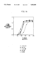
- FIG. 1A is a plot of transfer density against laser fluence, for a low coating weight.
- FIG. 1B is a plot of transfer density against laser fluence, for a high coating weight.
- This invention is a laser-induced melt transfer process which provides good density transfer of the imageable component onto the receiver element.
- the first step in the process of the invention is imagewise exposing a laserable assemblage to laser radiation.
- the laserable assemblage comprises 1) a donor element comprising a support having at least one layer and bearing on a first surface thereof (i) at least one imageable component and (ii) at least one melt viscosity modifier, wherein (i) and (ii) can be in the same or different layers, and 2) a receiver element situated proximally to the first surface of the donor element.
- the composition of the assemblage is discussed in detail below.
- the laser is preferably one emitting in the infrared, near-infrared or visible region. Particularly advantageous are diode lasers emitting in the region of 750 to 870 nm which offer substantial advantage in terms of their small size, low cost, stability, reliability, ruggedness and ease of modulation. Diode lasers emitting in the range of 800 to 840 nm are most preferred. Such lasers are available from, for example, Spectra Diode Laboratories (San Jose, Calif.).
- the exposure can take place through the support of the donor element or through the receiver element, provided that these, the donor support and the receiver element, are substantially transparent to the laser radiation.
- the donor support will be a film which is transparent to the laser radiation and the exposure is conveniently carried out through the support.
- the receiver element is substantially transparent to the laser radiation, the process of the invention can also be carried out by imagewise exposing the receiver element to laser radiation.
- a vacuum be applied to the assemblage during the exposure step.
- the vacuum provides good contact between the donor and receiver elements, and thus facilitates transfer to the receiver element.
- the vacuum can be conveniently applied as a vacuum drawdown on the bed of the laser imaging apparatus.
- the laserable assemblage is exposed imagewise so that material is transferred to the receiver element in a pattern.
- the pattern itself can be, for example, in the form of dots or linework generated by a computer, in a form obtained by scanning artwork to be copied, in the form of a digitized image taken from original artwork, or a combination of any of these forms which can be electronically combined on a computer prior to laser exposure.
- the laser beam and the laserable assemblage are in constant motion with respect of each other, such that each minute area of the assemblage ("pixel") is individually addressed by the laser. This is generally accomplished by mounting the laserable assemblage on a rotatable drum.
- a flat bed recorder can also be used.
- the next step in the process of the invention is separating the donor element from the receiver element. Usually this is done by simply peeling the two elements apart. This generally requires very little peel force, and is accomplished by simply separating the donor support from the receiver element. This can be done using any conventional separation technique and can be manual or automatic (without operator intervention).
- the donor element comprises a support having at least one layer and bearing on a first surface thereof (i) at least one imageable component and (ii) at least one melt viscosity modifier, wherein (i) and (ii) can be in the same or different layers.
- any dimensionally stable, sheet material can be used as the donor support.
- the support should also be capable of transmitting the laser radiation, and not be adversely affected by this radiation.
- suitable materials include, for example, polyesters, such as polyethylene terephthalate and polyethylene naphthanate; polyamides; polycarbonates; fluoropolymers; polyacetals; polyolefins; etc.
- a preferred support material is polyethylene terephthalate film.
- the donor support typically has a thickness of about 2 to about 250 micrometers, (0.1 to 10 mils). A preferred thickness is about 50 to 175 micrometers, (2 to 7 mils). As those skilled in the art will appreciate, some commercially available films will also have subbing layers. These can be used as well.
- the imageable component will depend on the intended application for the assemblage.
- the imageable component will be a colorant.
- Useful colorants include dyes and pigments.
- suitable dyes include the Intratherm® dyes available from Crompton and Knowles (Reading, Pa.) and the dyes disclosed by Evans et al. in U.S. Pat. Nos. 5,155,088, 5,134,115, 5,132,276, and 5,081,101.
- suitable inorganic pigments include carbon black and graphite.
- suitable organic pigments include Heliogen® Blue L6930; Rubine F6B (C.I. No. Pigment 184); Cromophthal® Yellow 3G (C.I. No.
- Pigment Yellow 93 Hostaperm® Yellow 3G (C.I. No. Pigment Yellow 154); Monastral® Violet R (C.I. No. Pigment Violet 19); 2,9-dimethylquinacridone (C. I. No. Pigment Red 122); Indofast® Brilliant Scarlet R6300 (C.I. No. Pigment Red 123); Quindo Magenta RV 6803; Monastral® Blue G (C.I. No. Pigment Blue 15); Monastral® Blue BT 383D (C.I. No. Pigment Blue 15); Monastral® Blue G BT 284D (C.I. No. Pigment Blue 15); and Monastral® Green GT 751D (C.I. No. Pigment Green 7). Combinations of pigments and/or dyes can also be used.
- the concentration of colorant will be chosen to achieve the optical density desired in the final image.
- the amount of colorant will depend on the thickness of the active layer and the absorption of the colorant.
- a dispersant is usually present when a pigment is to be transferred, in order to achieve maximum color strength, transparency and gloss.
- the dispersant generally an organic polymeric compound, is used to disperse the fine pigment particles and avoid flocculation and agglomeration.
- a wide range of dispersants is commercially available.
- a dispersant will be selected according to the characteristics of the pigment surface and other components in the composition as practiced by those skilled in the art. Conventional pigment dispersing techniques, such as ball milling, sand milling, etc., can be employed.
- the imageable component is an oleophilic, ink-receptive material.
- the oleophilic material is usually a film-forming polymeric material.
- suitable oleophilic materials include polymers and copolymers of acrylates and methacrylates; polyolefins; polyurethanes; polyesters; polyaramids; epoxy resins; novolak resins; and combinations thereof.
- Preferred oleophilic materials are acrylic polymers.
- a colorant can also be present.
- the colorant facilitates inspection of the plate after it is made. Any of the colorants discussed above can be used.
- the colorant can be a heat-, light-, or acid-sensitive color former.
- the colorant can be in a layer that is the same as or different from the layer containing the oleophilic material.
- the donor element further comprises at least one melt viscosity modifier (MVM).
- MVM melt viscosity modifier
- FIG. 1 This figure contains a family of curves in which transferred density is plotted against the laser fluence used for different amounts of MVM.
- a low coating weight on the donor element is used.
- a high coating weight is used.
- the curves all end at approximately the same transferred density.
- the addition of the MVM shifts the curve to lower fluences, meaning that lower laser power is necessary in order to transfer the imageable component to the same density.
- high coating weights are used, the coating without an MVM results in a lower transferred density even at the highest fluence level.
- lower laser fluence levels and higher donor coating weights can be used which results in much greater formulation latitude.
- the addition of the MVM may alter the mechanism by which the imageable component is transferred to the receiver element.
- the addition of the MVM allows the imageable component to be transferred by what is believed to be a melt transfer mechanism.
- the MVM lowers the softening point and the melt viscosity of the materials on the donor support, thus facilitating a melt transfer.
- the MVM should be compatible with the other materials on the donor element and lower their softening point.
- Types of materials which can be used as the MVM include plasticizers, monomers and low molecular weight oligomers.
- Plasticizers are well known and numerous examples can be found in the art. These include, for example, acetate esters of glycerine; polyesters of phthalic, adipic and benzoic acids; ethoxylated alcohols and phenols; and the like.
- Monomers and low molecular weight oligomers can also be used as the MVM. These include mono- and polyfunctional epoxides and aziridines; mono- and polyesters of acrylic and methacrylic acids with alcohols; mono- and divinyl ethers. Mixtures can also be used. Dibutyl phthalate and glyceryl tribenzoate are preferred as the MVM.
- these materials can be in a single layer on the support, or in different layers on the same side of the support.
- concentration of the various materials on the support will be stated relative to the weight of all the layers on the support, i.e., the total coating weight.
- typical colorant concentrations are 5 to 75% by weight, based on the total coating weight, preferably 20 to 40% by weight.
- a dispersant is generally present in a 1:1 to 1:3 dispersant-to-pigment ratio.
- the amount of oleophilic material is generally about 20 to 60% by weight, based on the total coating weight, preferably 30 to 50% by weight.
- the MVM is generally present in an amount of about 15 to 55% by weight, based on the total coating weight, preferably 25 to 45% by weight.
- the laser-radiation absorbing component is included in the donor element.
- the preferred lasers are those emitting in the infrared, near-infrared or visible regions.
- the laser-radiation absorbing component can comprise finely divided particles of metals such as aluminum, copper or zinc, one of the dark inorganic pigments, such as carbon black or graphite, or mixtures thereof.
- the laser-radiation absorbing component is preferably an infrared or near-IR absorbing dye, particularly for applications in which color images are formed.
- Suitable dyes which can be used alone or in combination include poly(substituted)phthalocyanine compounds and metal-containing phthalocyanine compounds; cyanine dyes; squarylium dyes; chalcogenopyryloarylidene dyes; croconium dyes; metal thiolate dyes; bis(chalcogenopyrylo)polymethine dyes; oxyindolizine dyes; bis(aminoaryl)polymethine dyes; merocyanine dyes; and quinoid dyes.
- Infrared-absorbing materials for laser-induced thermal imaging have been disclosed, for example, by: Barlow, U.S. Pat. No. 4,778,128; DeBoer, U.S. Pat.
- the laser-radiation absorbing component can be in the same layer as either the imageable component, or the MVM, or in a separate layer.
- the component generally has a concentration of about 1 to 10% by weight, based on the total coating weight; preferably 2 to 5% by weight.
- ingredients for example, surfactants, coating aids and binders, can be present in any of the layers on the support, provided that they: (i) are compatible with the other ingredients, (ii) do not adversely affect the properties of the assemblage in the practice of the process of the invention, and, (iii) for color imaging applications, do not impart unwanted color to the image.
- a polymeric binder can be used in addition to the imageable component and MVM.
- the binder should be of sufficiently high molecular weight that it is film forming, yet of sufficiently low molecular weight that it is soluble in the coating solvent.
- a surfactant can be present to improve the wetting and flow characteristics of the composition.
- compositions for the layer or layers to be coated onto the donor support can each be applied as a dispersion in a suitable solvent, however, it is preferred to coat them from a solution.
- Any suitable solvent can be used as a coating solvent, as long as it does not deleteriously affect the properties of the assemblage, using conventional coating techniques or printing techniques, for example, gravure printing.
- the receiver element typically comprises a receptor support and, optionally, an image-receiving layer.
- the receptor support comprises a dimensionally stable sheet material.
- the assemblage can be imaged through the receptor support if that support is transparent.
- transparent films include, for example polyethylene terephthalate, polyether sulfone, a polyimide, a poly(vinyl alcohol-co-acetal), or a cellulose ester, such as cellulose acetate.
- opaque supports materials include, for example, polyethylene terephthalate filled with a white pigment such as titanium dioxide, various paper substrates, or synthetic paper, such as Tyvek® spunbonded polyolefin.
- the support is typically a thin sheet of aluminum, such as anodized aluminum, or polyester.
- the receiver element typically has an additional receiving layer on one surface thereof.
- the receiving layer can be a coating of, for example, a polycarbonate, a polyurethane, a polyester, polvinyl chloride, styrene/acrylonitrile copolymer, poly(caprolactone), and mixtures thereof.
- This image receiving layer can be present in any amount effective for the intended purpose. In general, good results have been obtained at coating weights of 1 to 5 g/m 2 .
- the aluminum sheet is treated to form a layer of anodized aluminum on the surface as a receptor layer. Such treatments are well known in the lithographic art.
- the receiver element not be the final intended support for the imageable component.
- the receiver element can be an intermediate element and the laser imaging step can be followed by one or more transfer steps by which the imageable component is transferred to the final support. This is most likely to be the case for multicolor proofing applications in which the multicolor image is built up on the receiver element and then transferred to the permanent paper support.
- the following examples are intended to illustrate the practice of the invention and should not be construed as a limitation thereon.
- coating solution refers to the mixture of solvent and additives which is coated on the support. Amounts are expressed in parts by weight, unless otherwise specified.
- the components of the coating solution were combined in an amber glass bottle and rolled overnight to ensure complete mixing. (When a pigment was present in the composition, it was first mixed with the dispersant in a solvent on an attritor with steel balls for approximately 20 hours.) The mixed solution was then coated onto a 4 mil (0.010 cm) thick sheet of Mylar® polyester film (E. I. du Pont de Nemours and Company, Wilmington, Del.). The coating was air dried to form a donor element having a laserable layer having a dry thickness in the range from 0.3 to 2.0 micrometers depending on percent solids of the formulation and the blade used to coat the formulation onto the plate.
- Mylar® polyester film E. I. du Pont de Nemours and Company, Wilmington, Del.
- the receiver element was placed on the drum of a laser imaging apparatus such that the receiving layer, if present, is facing outward (away from the drum surface).
- the donor element was then placed on top of the receiver element such that the infrared sensitive layer was adjacent to the receiving side of the receiver element.
- a vacuum was then applied.
- Two types of laser imaging apparatuses were used. The first was a Crosfield Magnascan 646 (Crosfield Electronics, Ltd., London, England) which had been retrofitted with a CREO writehead (Creo Corp., Vancouver, BC) using an array of 36 infrared lasers emitting at 830 nm (SDL-7032-102 from Sanyo Semiconductor, Allendale, N.J.). The second type was a Creo Plotter (Creo Corp., Vancouver, BC) having 32 infrared lasers emitting at 830 nm. The laser fluence was calculated based on laser power and drum speed.
- This example illustrates the effect of the MVM on the binder.
- the binder used was EPT2678; HBVE and DBP were used as MVM.
- the components were mixed together at three different MVM:binder ratios.
- the Brookfield viscosity was measured on a Brookfield Viscometer, model DV-II, at 25° C. The results are given below.
- the resin without an MVM was a solid and thus the Brookfield viscosity was not measured.
- This example illustrates the effect of the MVM on transfer density.
- Cyan pigment was the imageable component; DBP or GTB was the MVM; EPT 2678 was the binder.
- the receiver element was paper. The Creo Plotter was used for imaging.
- Coating formulations were prepared as 10 wt % solids in MEK, having the following compositions:
- the coated samples were imaged over a range of laser fluences and the reflectance density of the image transferred to paper was measured as null density using the reflectance mode of a MacBeth densitometer.
- the results for the low coating weight samples are given in Table 2 below and in FIG. 1A.
- the results for the high coating weight samples are given in Table 3 below and in FIG. 1B.
- This example illustrates the effect of the MVM in a lithographic application.
- DER 665 functioned as the oleophilic material; DVE and CHVE were the MVM.
- DEH 82 was present for a post-transfer curing step.
- the receiver element was a sheet of anodized aluminum, Imperial type DE (Imperial Metal and Chemical Co., Philadelphia, Pa.).
- the Crosfield apparatus was used for imaging with a fluence level of about 800 mJ/cm 2 .
- Coating formulations were prepared as 15 wt % solids in MEK, having the following compositions:
- This example illustrates the ability to use lower levels of the laser-absorbing component when an MVM is present.
- a pigment was the imageable component; GTB was the MVM, E2010 and EPT2445 were binders.
- the receiver element was paper.
- the Creo Plotter was used for imaging.
- Coating formulations were prepared as 10 wt % solids in MEK, having the following compositions:
- melt process of the invention in which the MVM is present is much less sensitive to energy (laser fluence); (2) the melt process of the invention in which the MVM is present needs less laser absorbing component; and (3) the pigment loading to achieve equivalent densities is much lower when the MVM is present.
- This can result in greater formulation latitude which can be important in achieving SWOP densities. It also allows for the use of lower concentrations of laser absorbing components which can add unwanted color in proofing applications.
- This example illustrates several different formulations for proofing applications.
- the coatings were prepared at low and high coating weights as described in Example 2.
- Cyan pigment was the imageable component;
- BGE, DVE, CHVE and HBVE were used as the MVM;
- EPT2678 was the binder.
- Coating formulations were prepared at 11 wt % solids in MEK, having the following compositions:
- the coated samples were imaged using different laser fluences and the reflectance densities measures as described in Example 2.
- the results for the low coating weights are given in Table 5 below.
- the results for the high coating weight samples are given in Table 6 below.
Landscapes
- Physics & Mathematics (AREA)
- Optics & Photonics (AREA)
- Engineering & Computer Science (AREA)
- Mechanical Engineering (AREA)
- Manufacturing & Machinery (AREA)
- Thermal Transfer Or Thermal Recording In General (AREA)
Abstract
A laser-induced melt transfer process is described in which a melt viscosity modifier is used to facilitate the melt transfer process.
Description
This invention relates to a thermal transfer process and, in particular, to a laser-induced melt transfer process.
Laser-induced thermal transfer processes are well-known in applications such as color proofing and lithography. Such laser-induced processes include, for example, dye sublimation, dye transfer, ablative material transfer, and melt transfer of fusible materials such as waxes. Such processes are described in, for example, Baldock, UK Patent 2,083,726; DeBoer, U.S. Pat. No. 4,942,141; Kellogg, U.S. Pat. No. 5,019,549; Evans, U.S. Pat. No. 4,948,776; Foley et al., U.S. Pat. No. 5,156,938; Ellis et al., U.S. Pat. No. 5,171,650; and Koshizuka et al., U.S. Pat. No. 4,643,917. The processes use a laserable assemblage comprising a donor element that contains the imageable component, i.e., the material to be transferred, and a receiver element. The donor element is imagewise exposed by a laser, usually an infrared laser, resulting in transfer of material to the receiver element. The exposure takes place only in a small, selected region of the donor at one time, so that the transfer can be built up one pixel at a time. Computer control produces transfer with high resolution and at high speed.
For the preparation of images for proofing applications, the imageable component is a colorant. For the preparation of lithographic printing plates, the imageable component is an oleophilic material which will receive and transfer ink in printing. In general, when an infrared laser is used, a separate infrared radiation absorber is also included.
While all of the above processes have been used, they each suffer from certain disadvantages. Dyes used in dye sublimation and dye transfer processes are frequently unstable over long periods of time. It is also difficult to obtain colored images of sufficient density. In addition, the range of colors available is limited. Ablative transfer processes often require high laser power densities in order to transfer sufficient amounts of the imageable component. While sufficient transfer density can be obtained using melt transfer of fusible materials, it is frequently undesirable to have waxes in the final image. It is also difficult to obtain the necessary resolution with these systems.
This invention provides a laser-induced melt transfer process which comprises:
a) imagewise exposing to laser radiation a laserable assemblage comprising 1) a donor element comprising a support having at least one layer and bearing on a first surface thereof (i) at least one imageable component and (ii) at least one melt viscosity modifier, wherein (i) and (ii) can be in the same or different layers, and 2) a receiver element situated proximally to the first surface of the donor element, wherein a substantial portion of (i) and (ii) is transferred to the receiver element;
b) separating the donor element from the receiver element.
In a second embodiment this invention concerns a laser-induced melt transfer method for making a color image which comprises:
a) imagewise exposing to laser radiation a laserable assemblage comprising
1) a donor element comprising a support having at least one layer and bearing on a first surface thereof (i) at least one colorant and (ii) at least one melt viscosity modifier,
wherein (i) and (ii) can be in the same or different layers, and
2) a receiver element situated proximally to the first surface of the donor element, wherein a substantial portion of (i) and (ii) is transferred to the receiver element;
b) separating the donor element from the receiver element,
steps (a)-(b) being repeated at least once using the same receptor and a different donor element having a colorant the same as or different from the first colorant.
In a third embodiment this invention concerns a laser-induced melt transfer method for making a lithographic printing plate which comprises:
1) a donor element having at least one layer and bearing on a first surface thereof (i) at least one oleophilic resin, and (ii) at least one melt viscosity modifier,
wherein (i) and (ii) can be in the same or different layers, and
2) a receiver element situated proximally to the first surface of the donor element, wherein a substantial portion of (i) and (ii) is transferred to the receiver element;
b) separating the donor element from the receiver element.
FIG. 1A is a plot of transfer density against laser fluence, for a low coating weight.
FIG. 1B is a plot of transfer density against laser fluence, for a high coating weight.
This invention is a laser-induced melt transfer process which provides good density transfer of the imageable component onto the receiver element.
The first step in the process of the invention is imagewise exposing a laserable assemblage to laser radiation. The laserable assemblage comprises 1) a donor element comprising a support having at least one layer and bearing on a first surface thereof (i) at least one imageable component and (ii) at least one melt viscosity modifier, wherein (i) and (ii) can be in the same or different layers, and 2) a receiver element situated proximally to the first surface of the donor element. The composition of the assemblage is discussed in detail below.
Various types of lasers can be used to expose the laserable assemblage. The laser is preferably one emitting in the infrared, near-infrared or visible region. Particularly advantageous are diode lasers emitting in the region of 750 to 870 nm which offer substantial advantage in terms of their small size, low cost, stability, reliability, ruggedness and ease of modulation. Diode lasers emitting in the range of 800 to 840 nm are most preferred. Such lasers are available from, for example, Spectra Diode Laboratories (San Jose, Calif.).
The exposure can take place through the support of the donor element or through the receiver element, provided that these, the donor support and the receiver element, are substantially transparent to the laser radiation. In most cases, the donor support will be a film which is transparent to the laser radiation and the exposure is conveniently carried out through the support. However, if the receiver element is substantially transparent to the laser radiation, the process of the invention can also be carried out by imagewise exposing the receiver element to laser radiation.
It is preferred that a vacuum be applied to the assemblage during the exposure step. The vacuum provides good contact between the donor and receiver elements, and thus facilitates transfer to the receiver element. The vacuum can be conveniently applied as a vacuum drawdown on the bed of the laser imaging apparatus.
The laserable assemblage is exposed imagewise so that material is transferred to the receiver element in a pattern. The pattern itself can be, for example, in the form of dots or linework generated by a computer, in a form obtained by scanning artwork to be copied, in the form of a digitized image taken from original artwork, or a combination of any of these forms which can be electronically combined on a computer prior to laser exposure. The laser beam and the laserable assemblage are in constant motion with respect of each other, such that each minute area of the assemblage ("pixel") is individually addressed by the laser. This is generally accomplished by mounting the laserable assemblage on a rotatable drum. A flat bed recorder can also be used.
The next step in the process of the invention is separating the donor element from the receiver element. Usually this is done by simply peeling the two elements apart. This generally requires very little peel force, and is accomplished by simply separating the donor support from the receiver element. This can be done using any conventional separation technique and can be manual or automatic (without operator intervention).
The donor element comprises a support having at least one layer and bearing on a first surface thereof (i) at least one imageable component and (ii) at least one melt viscosity modifier, wherein (i) and (ii) can be in the same or different layers.
Any dimensionally stable, sheet material can be used as the donor support. When the laserable assemblage is to be imaged through the donor support, the support should also be capable of transmitting the laser radiation, and not be adversely affected by this radiation. Examples of suitable materials include, for example, polyesters, such as polyethylene terephthalate and polyethylene naphthanate; polyamides; polycarbonates; fluoropolymers; polyacetals; polyolefins; etc. A preferred support material is polyethylene terephthalate film. The donor support typically has a thickness of about 2 to about 250 micrometers, (0.1 to 10 mils). A preferred thickness is about 50 to 175 micrometers, (2 to 7 mils). As those skilled in the art will appreciate, some commercially available films will also have subbing layers. These can be used as well.
The nature of the imageable component will depend on the intended application for the assemblage. For imaging applications, the imageable component will be a colorant. Useful colorants include dyes and pigments. Examples of suitable dyes include the Intratherm® dyes available from Crompton and Knowles (Reading, Pa.) and the dyes disclosed by Evans et al. in U.S. Pat. Nos. 5,155,088, 5,134,115, 5,132,276, and 5,081,101. Examples of suitable inorganic pigments include carbon black and graphite. Examples of suitable organic pigments include Heliogen® Blue L6930; Rubine F6B (C.I. No. Pigment 184); Cromophthal® Yellow 3G (C.I. No. Pigment Yellow 93); Hostaperm® Yellow 3G (C.I. No. Pigment Yellow 154); Monastral® Violet R (C.I. No. Pigment Violet 19); 2,9-dimethylquinacridone (C. I. No. Pigment Red 122); Indofast® Brilliant Scarlet R6300 (C.I. No. Pigment Red 123); Quindo Magenta RV 6803; Monastral® Blue G (C.I. No. Pigment Blue 15); Monastral® Blue BT 383D (C.I. No. Pigment Blue 15); Monastral® Blue G BT 284D (C.I. No. Pigment Blue 15); and Monastral® Green GT 751D (C.I. No. Pigment Green 7). Combinations of pigments and/or dyes can also be used.
In accordance with principles well known to those skilled in the art, the concentration of colorant will be chosen to achieve the optical density desired in the final image. The amount of colorant will depend on the thickness of the active layer and the absorption of the colorant.
A dispersant is usually present when a pigment is to be transferred, in order to achieve maximum color strength, transparency and gloss. The dispersant, generally an organic polymeric compound, is used to disperse the fine pigment particles and avoid flocculation and agglomeration. A wide range of dispersants is commercially available. A dispersant will be selected according to the characteristics of the pigment surface and other components in the composition as practiced by those skilled in the art. Conventional pigment dispersing techniques, such as ball milling, sand milling, etc., can be employed.
For lithographic applications, the imageable component is an oleophilic, ink-receptive material. The oleophilic material is usually a film-forming polymeric material. Examples of suitable oleophilic materials include polymers and copolymers of acrylates and methacrylates; polyolefins; polyurethanes; polyesters; polyaramids; epoxy resins; novolak resins; and combinations thereof. Preferred oleophilic materials are acrylic polymers.
In lithographic applications a colorant can also be present. The colorant facilitates inspection of the plate after it is made. Any of the colorants discussed above can be used. The colorant can be a heat-, light-, or acid-sensitive color former. The colorant can be in a layer that is the same as or different from the layer containing the oleophilic material.
The donor element further comprises at least one melt viscosity modifier (MVM). Surprisingly, it has been found that the addition of an MVM to the donor element dramatically improves the transfer process. For a given coating weight, the addition of an MVM results in a lowering of the laser fluence necessary to produce a given transfer density. Laser fluence is defined herein as energy per unit area at full width half max of a gaussian beam.
The beneficial effect of the MVM is clearly illustrated by FIG. 1. This figure contains a family of curves in which transferred density is plotted against the laser fluence used for different amounts of MVM. In FIG. 1A a low coating weight on the donor element is used. In FIG. 1B a high coating weight is used. When low coating weights are used, the curves all end at approximately the same transferred density. However, the addition of the MVM shifts the curve to lower fluences, meaning that lower laser power is necessary in order to transfer the imageable component to the same density. When high coating weights are used, the coating without an MVM results in a lower transferred density even at the highest fluence level. Thus, when an MVM is present lower laser fluence levels and higher donor coating weights can be used which results in much greater formulation latitude.
While not wishing to be bound by any theory, it is believed that the addition of the MVM may alter the mechanism by which the imageable component is transferred to the receiver element. The addition of the MVM, allows the imageable component to be transferred by what is believed to be a melt transfer mechanism. As implied by the term, the MVM lowers the softening point and the melt viscosity of the materials on the donor support, thus facilitating a melt transfer.
The MVM should be compatible with the other materials on the donor element and lower their softening point. Types of materials which can be used as the MVM include plasticizers, monomers and low molecular weight oligomers. Plasticizers are well known and numerous examples can be found in the art. These include, for example, acetate esters of glycerine; polyesters of phthalic, adipic and benzoic acids; ethoxylated alcohols and phenols; and the like. Monomers and low molecular weight oligomers can also be used as the MVM. These include mono- and polyfunctional epoxides and aziridines; mono- and polyesters of acrylic and methacrylic acids with alcohols; mono- and divinyl ethers. Mixtures can also be used. Dibutyl phthalate and glyceryl tribenzoate are preferred as the MVM.
When more than one material is to be transferred, these materials can be in a single layer on the support, or in different layers on the same side of the support. The concentration of the various materials on the support will be stated relative to the weight of all the layers on the support, i.e., the total coating weight. Depending upon the desired optical density, typical colorant concentrations are 5 to 75% by weight, based on the total coating weight, preferably 20 to 40% by weight. For optimum particle size, a dispersant is generally present in a 1:1 to 1:3 dispersant-to-pigment ratio. The amount of oleophilic material is generally about 20 to 60% by weight, based on the total coating weight, preferably 30 to 50% by weight. The MVM is generally present in an amount of about 15 to 55% by weight, based on the total coating weight, preferably 25 to 45% by weight.
In most cases it is desirable to have a laser-radiation absorbing component included in the donor element. The preferred lasers are those emitting in the infrared, near-infrared or visible regions. For those lasers, the laser-radiation absorbing component can comprise finely divided particles of metals such as aluminum, copper or zinc, one of the dark inorganic pigments, such as carbon black or graphite, or mixtures thereof. For infrared and near-infrared lasers, the laser-radiation absorbing component is preferably an infrared or near-IR absorbing dye, particularly for applications in which color images are formed. Suitable dyes which can be used alone or in combination include poly(substituted)phthalocyanine compounds and metal-containing phthalocyanine compounds; cyanine dyes; squarylium dyes; chalcogenopyryloarylidene dyes; croconium dyes; metal thiolate dyes; bis(chalcogenopyrylo)polymethine dyes; oxyindolizine dyes; bis(aminoaryl)polymethine dyes; merocyanine dyes; and quinoid dyes. Infrared-absorbing materials for laser-induced thermal imaging have been disclosed, for example, by: Barlow, U.S. Pat. No. 4,778,128; DeBoer, U.S. Pat. Nos. 4,942,141, 4,948,778, and 4,950,639; Kellogg, U.S. Pat. No. 5,019,549; Evans, U.S. Pat. Nos. 4,948,776 and 4,948,777; and Chapman, U.S. Pat. No. 4,952,552.
The laser-radiation absorbing component can be in the same layer as either the imageable component, or the MVM, or in a separate layer. When present, the component generally has a concentration of about 1 to 10% by weight, based on the total coating weight; preferably 2 to 5% by weight.
Other ingredients, for example, surfactants, coating aids and binders, can be present in any of the layers on the support, provided that they: (i) are compatible with the other ingredients, (ii) do not adversely affect the properties of the assemblage in the practice of the process of the invention, and, (iii) for color imaging applications, do not impart unwanted color to the image.
A polymeric binder can be used in addition to the imageable component and MVM. The binder should be of sufficiently high molecular weight that it is film forming, yet of sufficiently low molecular weight that it is soluble in the coating solvent. A surfactant can be present to improve the wetting and flow characteristics of the composition.
The compositions for the layer or layers to be coated onto the donor support can each be applied as a dispersion in a suitable solvent, however, it is preferred to coat them from a solution. Any suitable solvent can be used as a coating solvent, as long as it does not deleteriously affect the properties of the assemblage, using conventional coating techniques or printing techniques, for example, gravure printing.
The receiver element typically comprises a receptor support and, optionally, an image-receiving layer. The receptor support comprises a dimensionally stable sheet material. As noted above, the assemblage can be imaged through the receptor support if that support is transparent. Examples of transparent films include, for example polyethylene terephthalate, polyether sulfone, a polyimide, a poly(vinyl alcohol-co-acetal), or a cellulose ester, such as cellulose acetate. Examples of opaque supports materials include, for example, polyethylene terephthalate filled with a white pigment such as titanium dioxide, various paper substrates, or synthetic paper, such as Tyvek® spunbonded polyolefin. For lithographic printing applications, the support is typically a thin sheet of aluminum, such as anodized aluminum, or polyester.
Although the imageable component can be transferred directly to the receptor support, the receiver element typically has an additional receiving layer on one surface thereof. For image formation applications, the receiving layer can be a coating of, for example, a polycarbonate, a polyurethane, a polyester, polvinyl chloride, styrene/acrylonitrile copolymer, poly(caprolactone), and mixtures thereof. This image receiving layer can be present in any amount effective for the intended purpose. In general, good results have been obtained at coating weights of 1 to 5 g/m2. For lithographic applications, typically the aluminum sheet is treated to form a layer of anodized aluminum on the surface as a receptor layer. Such treatments are well known in the lithographic art.
It is also possible that the receiver element not be the final intended support for the imageable component. The receiver element can be an intermediate element and the laser imaging step can be followed by one or more transfer steps by which the imageable component is transferred to the final support. This is most likely to be the case for multicolor proofing applications in which the multicolor image is built up on the receiver element and then transferred to the permanent paper support. The following examples are intended to illustrate the practice of the invention and should not be construed as a limitation thereon.
______________________________________
EXAMPLES
GLOSSARY:
______________________________________
BGE       butyl glycidyl ether
CHVE      1,4-bis[(vinyloxy)methyl]cyclohexane
CY 179    cycloaliphatic liquid epoxy resin;
          Araldite ® CY 179 from Ciba-Geigy
Cyan      Heliogen ® blue pigment L6930; added as a
          20/10/70 dispersion of pigment/RCH-87763
          dispersant/solvent (MEK or NBA)
DBP       dibutyl phthalate
DEH 82    epoxy during agent: 65-69% bisphenol
          A epoxy resin; 24-29% bisphenol A;
          3.5% 2-methylimidazole; 2.5%
          polyacrylate flow modifier; from Dow
          Chemical Co., Midland, MI
DER 6225  medium molecular weight bisphenol A-based
          epoxy resin, melt viscosity (150° C.)
          800-1600 cs; from Dow Chemical Co.,
          Midland, MI
DER 642U  high molecular weight novolac modified
          epoxy resin, melt viscosity (150° C.)
          2000-4000 cs; from Dow Chemical Co.,
          Midland, MI
DER 661   low molecular weight bisphenol A-based
          epoxy, melt viscosity (150° C.) 400-800 cs;
          from Dow Chemical Co., Midland. MI
DER 665U  high molecular weight bisphenol A-based
          epoxy resin, melt viscosity (150° C.)
          10,000-30,000 cs; from Dow Chemical Co.,
          Midland, MI
DER 668   high molecular weight bisphenol A-based
          epoxy resin, Gardner viscosity at 40%
          non-volatile in Dowanole ® DB glycol ether
          Z-Z4; from DOW Chemical Co., Midland, MI
DVE       triethylene glycol divinyl ether
E2010     medium molecular weight methacrylate
          polymer; Elvacitee ® 2010 from E.I.
          du Pont de Nemours and Company,
          Wilmington, DE
EPT2445   low molecular weight
          polymethylmethacrylate, MK about 10,000
EPT2519   methacrylate terpolymer with 16 wt %
          glycidyl methacrylate
EPT2678   methacrylate terpolymer with 7.5 wt %
          glycidyl methacrylate
GTB       glyceryl tribenzoate; Uniplex ® 260 from
          Unitex Chemical Corp.
HBVE      4-(ethenyloxy)-1-butanol
MEK       methyl ethyl ketone
NBA       n-butyl acetate
PMMA      methyl methacrylate polymer
RCH 87763 AB dispersant
SQS       near-IR dye; 4-[3-[2,6-Bix(1,10-
          dimethylethyl)-
          4H-thiopyran-4-ylidene]methyl]-2-
          hydroxy-4-oxo-2-cyclobuten-1-ylidene]
          methyl-2,6-bis(1,1-diethylethyl)
          thiopyrylium hydroxide, inner salt
T-785     solid epoxy-novolac resin; TACTIX 785
          from Dow Chemical Co., Midland, MI
TIC-5C    near-IR dye; 3H-Indolium, 2-[2-[2-chloro-
          3-[2-
          (1,3-dihydro-2H-indol-2-ylidene)
          ethylidene]-1-cyclopenten-1-yl]
          ethenyl]-1,3,3-trimethyl-
          trifluoromethanesulfonate
______________________________________
In the examples which follow, "coating solution" refers to the mixture of solvent and additives which is coated on the support. Amounts are expressed in parts by weight, unless otherwise specified.
The components of the coating solution were combined in an amber glass bottle and rolled overnight to ensure complete mixing. (When a pigment was present in the composition, it was first mixed with the dispersant in a solvent on an attritor with steel balls for approximately 20 hours.) The mixed solution was then coated onto a 4 mil (0.010 cm) thick sheet of Mylar® polyester film (E. I. du Pont de Nemours and Company, Wilmington, Del.). The coating was air dried to form a donor element having a laserable layer having a dry thickness in the range from 0.3 to 2.0 micrometers depending on percent solids of the formulation and the blade used to coat the formulation onto the plate.
The receiver element was placed on the drum of a laser imaging apparatus such that the receiving layer, if present, is facing outward (away from the drum surface). The donor element was then placed on top of the receiver element such that the infrared sensitive layer was adjacent to the receiving side of the receiver element. A vacuum was then applied. Two types of laser imaging apparatuses were used. The first was a Crosfield Magnascan 646 (Crosfield Electronics, Ltd., London, England) which had been retrofitted with a CREO writehead (Creo Corp., Vancouver, BC) using an array of 36 infrared lasers emitting at 830 nm (SDL-7032-102 from Sanyo Semiconductor, Allendale, N.J.). The second type was a Creo Plotter (Creo Corp., Vancouver, BC) having 32 infrared lasers emitting at 830 nm. The laser fluence was calculated based on laser power and drum speed.
              TABLE 1
______________________________________
CALCULATED LASER FLUENCE vs. DRUM SPEED
Drum speed/fluence correlation
Pitch  r(1/e.sup.2)
                 Fluence (FWHM)
                              Drum Velocity
(uM)   (uM)      (mJ/cm.sup.2)
                              (rpm)
______________________________________
2.9    3.9       100          370
                 150          246
                 200          185
                 250          148
                 300          123
                 350          106
______________________________________
When the vacuum was removed the donor element separated from the receiver element.
This example illustrates the effect of the MVM on the binder. The binder used was EPT2678; HBVE and DBP were used as MVM.
The components were mixed together at three different MVM:binder ratios. The Brookfield viscosity was measured on a Brookfield Viscometer, model DV-II, at 25° C. The results are given below. The resin without an MVM was a solid and thus the Brookfield viscosity was not measured.
______________________________________
         Brookfield Viscosity
           HBVE           DBP
MVM:Resin  (Spindle #, Speed)
                          (Spindle #, Speed)
______________________________________
1:1        5740 (2, 3)    782,000 (4, 0.3)
2:1        210 (2, 12)    4,210 (3, 3)
3:1        63 (2, 12)     521 (3, 3)
______________________________________
It is clear that both MVM compounds lower the viscosity of the binder. In this case, HBVE is more effective at lowering the viscosity.
This example illustrates the effect of the MVM on transfer density.
Cyan pigment was the imageable component; DBP or GTB was the MVM; EPT 2678 was the binder. The receiver element was paper. The Creo Plotter was used for imaging.
Coating formulations were prepared as 10 wt % solids in MEK, having the following compositions:
______________________________________
        Weight % (Dry coating basis)
Component Control    2A     2B     2C   2D
______________________________________
Cyan      45         45     45     45   45
DBP       0          12.5   25     0    0
GTB       0          0      0      12.5 25
E2678     50         37.5   25     7.5  25
SQS       5          5.0    5.0    5.0  5
______________________________________
These formulations were first coated onto Mylar® using a 1.5 μm blade to obtain a low coating weight. A second coating was made for each formulation using a 3.0 μm blade to obtain a high coating weight.
The coated samples were imaged over a range of laser fluences and the reflectance density of the image transferred to paper was measured as null density using the reflectance mode of a MacBeth densitometer. The results for the low coating weight samples are given in Table 2 below and in FIG. 1A. The results for the high coating weight samples are given in Table 3 below and in FIG. 1B.
              TABLE 2
______________________________________
Low Coating Weights
         Density Transferred
Fluence (mJ/cm.sup.2)
           Control   2A      2B    2C    2D
______________________________________
100        0.00      0.00    0.00  0.00  0.00
175        0.00      0.28    0.48  0.24  0.14
250        0.19      1.08    1.12  0.90  1.08
325        0.89      1.18    1.20  1.09  1.18
400        1.14      1.19    1.21  1.14  1.24
475        1.19      1.23    1.13  1.11  1.22
______________________________________
              TABLE 3
______________________________________
High Coating Weights
         Density Transferred
Fluence (mJ/cm.sup.2)
           Control   2A      2B    2C    2D
______________________________________
100        0.00      0.00    0.00  0.00  0.00
175        0.00      0.00    0.03  0.00  0.08
250        0.00      0.29    1.06  0.53  1.24
325        0.01      0.96    1.18  0.93  1.29
400        0.15      1.20    1.30  1.20  1.34
475        0.77      1.32    1.29  1.34  1.40
______________________________________
It is clear from the tables and graphs that transferred pigment density is greater when the MVM is present except at the highest fluence levels. In the absence of the MVM, transferred pigment density actually decreases as the coating weight is increased.
This example illustrates the effect of the MVM in a lithographic application.
DER 665 functioned as the oleophilic material; DVE and CHVE were the MVM. DEH 82 was present for a post-transfer curing step. The receiver element was a sheet of anodized aluminum, Imperial type DE (Imperial Metal and Chemical Co., Philadelphia, Pa.). The Crosfield apparatus was used for imaging with a fluence level of about 800 mJ/cm2.
Coating formulations were prepared as 15 wt % solids in MEK, having the following compositions:
______________________________________
           Weight % (dry coating basis)
Component    Control       Sample 3
______________________________________
DEH 82       3.5           3.5
DVE          0             23.5
CHVE         0             23.5
TIC-5C       3.5           3.5
DER 665U     93.0          46.0
______________________________________
With the control, little or no transfer to the surface of the aluminum plate was observed. Good transfer was observed with Sample 3, visible as a greenish image, colored by the presence of the near-IR dye, TIC-5C. The thickness of the image on the aluminum receiver element was measured using a DEKTAK profilometer and found to be approximately 1.5 to 2.0 micrometers.
This example illustrates the ability to use lower levels of the laser-absorbing component when an MVM is present.
A pigment was the imageable component; GTB was the MVM, E2010 and EPT2445 were binders.
The receiver element was paper. The Creo Plotter was used for imaging.
Coating formulations were prepared as 10 wt % solids in MEK, having the following compositions:
______________________________________
       Component
Sample   Cyan    E2010    EPT2445 GTB   SOS
______________________________________
Controls
(no MVM)
C4-A     75      15.9     0       0     9.1
C4-B     78.6    16.7     0       0     4.8
C4-C     79.5    16.9     0       0     3.6
C4-D     80.5    17.1     0       0     2.4
C4-E     81.5    17.3     0       0     1.2
C4-F     82.5    17.5     0       0     0
With MVM
4-A      27.3    0        22.7    40.9  9.1
4-B      28.6    0        23.8    42.9  4.8
4-C      28.9    0        24.1    43.4  3.6
4-D      29.3    0        24.4    43.9  2.4
4-E      29.6    0        24.7    44.4  1.2
4-F      30      0        25      45    0
______________________________________
The samples were imaged at three different fluence levels. The density transferred was measured as described above. The results are given in Table 4.
              TABLE 4
______________________________________
         Density Transferred
Sample     308         231    184 mJ/cm.sup.2
______________________________________
No MVM
C4-A       0.84        0.64   0.34
C4-B       0.57        0.40   0.17
C4-C       0.53        0.28   0.15
C4-D       0.30        0.13   0.04
C4-E       0.03        0.00   0.00
C4-F       0.00        0.00   0.00
With MVM
4-A        0.83        0.97   0.85
4-B        0.90        0.93   0.75
4-C        0.85        0.95   0.68
4-D        0.86        0.80   0.35
4-E        0.72        0.33   0.11
4-F        0.00        0.00   0.00
______________________________________
From these results it can be seen that (1) the melt process of the invention in which the MVM is present is much less sensitive to energy (laser fluence); (2) the melt process of the invention in which the MVM is present needs less laser absorbing component; and (3) the pigment loading to achieve equivalent densities is much lower when the MVM is present. This can result in greater formulation latitude which can be important in achieving SWOP densities. It also allows for the use of lower concentrations of laser absorbing components which can add unwanted color in proofing applications.
This example illustrates several different formulations for proofing applications.
The coatings were prepared at low and high coating weights as described in Example 2. Cyan pigment was the imageable component; BGE, DVE, CHVE and HBVE were used as the MVM; EPT2678 was the binder.
Coating formulations were prepared at 11 wt % solids in MEK, having the following compositions:
__________________________________________________________________________
Weight % (Dry Coating Basis)
Component
      Control
           5A 5B  5C 5D  5E 5F  5G 5H
__________________________________________________________________________
Cyan  45.0 45.0
              45.0
                  45.0
                     45.0
                         45.0
                            45.0
                                45.0
                                   45.0
EPT2678
      50.0 37.5
              37.5
                  37.5
                     37.5
                         25.0
                            25.0
                                25.0
                                   25.0
SQS   5.0  5.0
              5.0 5.0
                     5.0 5.0
                            5.0 5.0
                                   5.0
BGE   --   12.5
              --  -- --  25.0
                            --  -- --
DVE   --   -- 12.5
                  -- --  -- 25.0
                                -- --
CHVE  --   -- --  12.5
                     --  -- --  25.0
                                   --
HBVE  --   -- --  -- 12.5
                         -- --  -- 25.0
__________________________________________________________________________
The coated samples were imaged using different laser fluences and the reflectance densities measures as described in Example 2. The results for the low coating weights are given in Table 5 below. The results for the high coating weight samples are given in Table 6 below.
                                  TABLE 5
__________________________________________________________________________
Low Coating Weights
Fluence
     Density Transferred
(mJ/cm.sup.2
     Control
          5A  5B  5C 5D  5E 5F  5G 5H
__________________________________________________________________________
100  0.00 0.00
              0.00
                  0.00
                     0.00
                         0.00
                            0.00
                                0.00
                                   0.00
175  0.00 0.07
              0.39
                  0.12
                     0.09
                         0.23
                            1.04
                                0.27
                                   0.19
250  0.19 0.75
              1.01
                  0.82
                     0.85
                         0.84
                            1.20
                                0.83
                                   0.80
325  0.89 1.00
              1.08
                  1.02
                     1.04
                         1.05
                            1.20
                                1.03
                                   1.02
400  1.14 1.08
              1.13
                  1.16
                     1.11
                         1.12
                            1.18
                                1.08
                                   1.10
475  1.19 1.06
              1.15
                  1.16
                     1.17
                         1.12
                            1.16
                                1.10
                                   1.03
__________________________________________________________________________
                                  TABLE 6
__________________________________________________________________________
High Coating Weights
Fluence
     Density Transferred
(mJ/cm.sup.2
     Control
          5A  5B  5C 5D  5E 5F  5G 5H
__________________________________________________________________________
100  0.00 0.00
              0.00
                  0.00
                     0.00
                         0.00
                            0.00
                                0.00
                                   0.00
175  0.00 0.00
              0.00
                  0.00
                     0.00
                         0.00
                            0.25
                                0.00
                                   0.00
250  0.00 0.02
              0.75
                  0.17
                     0.13
                         0.07
                            1.22
                                0.90
                                   0.04
325  0.01 0.25
              1.14
                  0.95
                     0.90
                         0.80
                            1.20
                                1.00
                                   0.86
400  0.15 0.77
              1.25
                  1.16
                     1.09
                         1.05
                            1.26
                                1.27
                                   1.14
475  0.77 1.03
              1.31
                  1.27
                     1.19
                         1.17
                            1.25
                                1.28
                                   1.17
__________________________________________________________________________
From this data it appears that the best performance is obtained using the higher level of DVE as the MVM (sample 5B) at the lower coating weight. High pigment density is transferred at a relatively low fluence.
Claims (3)
1. A laser-induced melt transfer method for making a color image which consists essentially of:
a) imagewise exposing to laser radiation a laserable assemblage comprising
1) a donor element consisting essentially of a support bearing on a first surface thereof a composition selected from the group consisting of:
(A)(i) at least one colorant and (ii) at least one melt viscosity modifier to lower melt viscosity,
(B)(i) at least one colorant, (ii) at least one melt viscosity modifier to lower melt viscosity, and (iii) a binder,
(C)(i) at least one colorant, (ii) at least one melt viscosity modifier to lower melt viscosity, and (iv) a laser radiation absorbing component, and
(D)(i)at least one colorant, (ii) at least one melt viscosity modifier to lower melt viscosity, (iii) a binder and (iv) a laser radiation absorbing component,
wherein (i) and (ii) can be in the same or different layers, and
2) a receiver element situated proximally to the first surface of the donor element, wherein a substantial portion of (i) and (ii) is transferred to the receiver element;
b) separating the donor element from the receiver element,
steps (a)-(b) being repeated at least once using the same receptor and a different donor element having a colorant the same as or different from the first colorant.
2. A process according to claim 1 wherein the receiver element is paper.
3. A process according to claim 1 wherein the laser radiation is in the IR, near-IR, or visible region.
Priority Applications (5)
| Application Number | Priority Date | Filing Date | Title |
|---|---|---|---|
| US08/103,302 US5401606A (en) | 1993-04-30 | 1993-04-30 | Laser-induced melt transfer process |
| JP6524357A JPH08510177A (en) | 1993-04-30 | 1994-04-25 | Laser-induced melt transfer method |
| EP94915831A EP0696246B1 (en) | 1993-04-30 | 1994-04-25 | Laser-induced melt transfer process |
| PCT/US1994/004300 WO1994025283A1 (en) | 1993-04-30 | 1994-04-25 | Laser-induced melt transfer process |
| DE69412475T DE69412475T2 (en) | 1993-04-30 | 1994-04-25 | LASER-INDUCED MELT TRANSFER METHOD |
Applications Claiming Priority (1)
| Application Number | Priority Date | Filing Date | Title |
|---|---|---|---|
| US08/103,302 US5401606A (en) | 1993-04-30 | 1993-04-30 | Laser-induced melt transfer process |
Publications (1)
| Publication Number | Publication Date |
|---|---|
| US5401606A true US5401606A (en) | 1995-03-28 |
Family
ID=22294470
Family Applications (1)
| Application Number | Title | Priority Date | Filing Date |
|---|---|---|---|
| US08/103,302 Expired - Lifetime US5401606A (en) | 1993-04-30 | 1993-04-30 | Laser-induced melt transfer process |
Country Status (5)
| Country | Link |
|---|---|
| US (1) | US5401606A (en) |
| EP (1) | EP0696246B1 (en) |
| JP (1) | JPH08510177A (en) |
| DE (1) | DE69412475T2 (en) |
| WO (1) | WO1994025283A1 (en) |
Cited By (19)
| Publication number | Priority date | Publication date | Assignee | Title |
|---|---|---|---|---|
| US5593803A (en) * | 1995-08-03 | 1997-01-14 | Minnesota Mining And Manufacturing Company | Process for applying images to non-adhesive surfaces in thermal dye transfer imaging |
| US5705310A (en) * | 1995-05-01 | 1998-01-06 | E. I. Du Pont De Nemours And Company | Flexographic printing plate |
| US5757313A (en) * | 1993-11-09 | 1998-05-26 | Markem Corporation | Lacer-induced transfer printing medium and method |
| US5843617A (en) * | 1996-08-20 | 1998-12-01 | Minnesota Mining & Manufacturing Company | Thermal bleaching of infrared dyes |
| US5856061A (en) * | 1997-08-14 | 1999-01-05 | Minnesota Mining And Manufacturing Company | Production of color proofs and printing plates |
| US5935758A (en) * | 1995-04-20 | 1999-08-10 | Imation Corp. | Laser induced film transfer system |
| US5945249A (en) * | 1995-04-20 | 1999-08-31 | Imation Corp. | Laser absorbable photobleachable compositions |
| US6001530A (en) * | 1997-09-02 | 1999-12-14 | Imation Corp. | Laser addressed black thermal transfer donors |
| US6197474B1 (en) * | 1999-08-27 | 2001-03-06 | Eastman Kodak Company | Thermal color proofing process |
| US6461793B2 (en) | 1996-04-15 | 2002-10-08 | 3M Innovative Properties Company | Laser addressable thermal transfer imaging element with an interlayer |
| US6737204B2 (en) | 2001-09-04 | 2004-05-18 | Kodak Polychrome Graphics, Llc | Hybrid proofing method |
| US6855474B1 (en) | 2004-05-03 | 2005-02-15 | Kodak Polychrome Graphics Llc | Laser thermal color donors with improved aging characteristics |
| US20050041093A1 (en) * | 2003-08-22 | 2005-02-24 | Zwadlo Gregory L. | Media construction for use in auto-focus laser |
| US6894713B2 (en) | 2002-02-08 | 2005-05-17 | Kodak Polychrome Graphics Llc | Method and apparatus for laser-induced thermal transfer printing |
| US20050287315A1 (en) * | 1996-04-15 | 2005-12-29 | 3M Innovative Properties Company | Texture control of thin film layers prepared via laser induced thermal imaging |
| US20060090661A1 (en) * | 2002-02-08 | 2006-05-04 | Eastman Kodak Company | Method and apparatus for laser induced thermal transfer printing |
| US20070082288A1 (en) * | 2005-10-07 | 2007-04-12 | Wright Robin E | Radiation curable thermal transfer elements |
| US20080241733A1 (en) * | 2005-10-07 | 2008-10-02 | 3M Innovative Properties Company | Radiation curable thermal transfer elements |
| US7910223B2 (en) | 2003-07-17 | 2011-03-22 | Honeywell International Inc. | Planarization films for advanced microelectronic applications and devices and methods of production thereof |
Families Citing this family (1)
| Publication number | Priority date | Publication date | Assignee | Title |
|---|---|---|---|---|
| US5739189A (en) * | 1995-12-18 | 1998-04-14 | Ncr Corporation | Low energy thermal transfer formulation |
Citations (15)
| Publication number | Priority date | Publication date | Assignee | Title |
|---|---|---|---|---|
| US3129661A (en) * | 1960-03-31 | 1964-04-21 | Columbia Ribbon & Carbon | Novel duplicating processes |
| US3833441A (en) * | 1962-10-24 | 1974-09-03 | Du Pont | Thermographic processes |
| US3962513A (en) * | 1974-03-28 | 1976-06-08 | Scott Paper Company | Laser transfer medium for imaging printing plate |
| US3964389A (en) * | 1974-01-17 | 1976-06-22 | Scott Paper Company | Printing plate by laser transfer |
| US3975563A (en) * | 1974-05-08 | 1976-08-17 | Minnesota Mining And Manufacturing Company | Image transfer sheet material |
| US4245003A (en) * | 1979-08-17 | 1981-01-13 | James River Graphics, Inc. | Coated transparent film for laser imaging |
| JPS6141547A (en) * | 1984-08-02 | 1986-02-27 | Toppan Printing Co Ltd | Manufacture of printing plate |
| US4626493A (en) * | 1984-04-25 | 1986-12-02 | Imperial Chemical Industries Plc | Laser-imageable assembly with heterogeneous resin layer and process for production thereof |
| US4914078A (en) * | 1987-04-24 | 1990-04-03 | Imperial Chemical Industries Plc | Thermal transfer receiver |
| US5064743A (en) * | 1988-05-18 | 1991-11-12 | Konica Corporation | Thermal transfer recording medium |
| US5089372A (en) * | 1986-09-01 | 1992-02-18 | Tomoegawa Paper Co., Ltd. | Transfer recording medium utilizing diazo or azide compounds wherein light energy is converted to heat energy |
| EP0530018A1 (en) * | 1991-08-29 | 1993-03-03 | Imperial Chemical Industries Plc | A thermal melt transfer colour ink sheet |
| EP0531580A1 (en) * | 1991-09-10 | 1993-03-17 | Agfa-Gevaert N.V. | Dye-donor element for use according to thermal dye sublimation transfer |
| US5232817A (en) * | 1990-12-21 | 1993-08-03 | Konica Corporation | Thermal transfer image receiving material and method for preparing therefrom a proof for printing |
| US5238778A (en) * | 1990-08-13 | 1993-08-24 | Konica Corporation | Method of forming printing plates by heat transfer |
Family Cites Families (5)
| Publication number | Priority date | Publication date | Assignee | Title |
|---|---|---|---|---|
| IT1145104B (en) * | 1981-09-21 | 1986-11-05 | Olivetti & Co Spa | THERMAL SENSITIVE INK ELEMENT FOR PRINTERS WITHOUT THERMAL IMPACT |
| JP2644999B2 (en) * | 1986-11-19 | 1997-08-25 | 花王株式会社 | Thermal transfer ink |
| US4876236A (en) * | 1987-12-04 | 1989-10-24 | Eastman Kodak Company | Material for increasing dye transfer efficiency in dye-donor elements used in thermal dye transfer |
| JPH0343295A (en) * | 1989-07-11 | 1991-02-25 | Seiko Epson Corp | Thermally transferable recording medium |
| US5395729A (en) * | 1993-04-30 | 1995-03-07 | E. I. Du Pont De Nemours And Company | Laser-induced thermal transfer process |
-
1993
- 1993-04-30 US US08/103,302 patent/US5401606A/en not_active Expired - Lifetime
-
1994
- 1994-04-25 WO PCT/US1994/004300 patent/WO1994025283A1/en not_active Application Discontinuation
- 1994-04-25 EP EP94915831A patent/EP0696246B1/en not_active Revoked
- 1994-04-25 DE DE69412475T patent/DE69412475T2/en not_active Revoked
- 1994-04-25 JP JP6524357A patent/JPH08510177A/en active Pending
Patent Citations (15)
| Publication number | Priority date | Publication date | Assignee | Title |
|---|---|---|---|---|
| US3129661A (en) * | 1960-03-31 | 1964-04-21 | Columbia Ribbon & Carbon | Novel duplicating processes |
| US3833441A (en) * | 1962-10-24 | 1974-09-03 | Du Pont | Thermographic processes |
| US3964389A (en) * | 1974-01-17 | 1976-06-22 | Scott Paper Company | Printing plate by laser transfer |
| US3962513A (en) * | 1974-03-28 | 1976-06-08 | Scott Paper Company | Laser transfer medium for imaging printing plate |
| US3975563A (en) * | 1974-05-08 | 1976-08-17 | Minnesota Mining And Manufacturing Company | Image transfer sheet material |
| US4245003A (en) * | 1979-08-17 | 1981-01-13 | James River Graphics, Inc. | Coated transparent film for laser imaging |
| US4626493A (en) * | 1984-04-25 | 1986-12-02 | Imperial Chemical Industries Plc | Laser-imageable assembly with heterogeneous resin layer and process for production thereof |
| JPS6141547A (en) * | 1984-08-02 | 1986-02-27 | Toppan Printing Co Ltd | Manufacture of printing plate |
| US5089372A (en) * | 1986-09-01 | 1992-02-18 | Tomoegawa Paper Co., Ltd. | Transfer recording medium utilizing diazo or azide compounds wherein light energy is converted to heat energy |
| US4914078A (en) * | 1987-04-24 | 1990-04-03 | Imperial Chemical Industries Plc | Thermal transfer receiver |
| US5064743A (en) * | 1988-05-18 | 1991-11-12 | Konica Corporation | Thermal transfer recording medium |
| US5238778A (en) * | 1990-08-13 | 1993-08-24 | Konica Corporation | Method of forming printing plates by heat transfer |
| US5232817A (en) * | 1990-12-21 | 1993-08-03 | Konica Corporation | Thermal transfer image receiving material and method for preparing therefrom a proof for printing |
| EP0530018A1 (en) * | 1991-08-29 | 1993-03-03 | Imperial Chemical Industries Plc | A thermal melt transfer colour ink sheet |
| EP0531580A1 (en) * | 1991-09-10 | 1993-03-17 | Agfa-Gevaert N.V. | Dye-donor element for use according to thermal dye sublimation transfer |
Cited By (33)
| Publication number | Priority date | Publication date | Assignee | Title |
|---|---|---|---|---|
| US5757313A (en) * | 1993-11-09 | 1998-05-26 | Markem Corporation | Lacer-induced transfer printing medium and method |
| US6171766B1 (en) | 1995-04-20 | 2001-01-09 | Imation Corp. | Laser absorbable photobleachable compositions |
| US6291143B1 (en) | 1995-04-20 | 2001-09-18 | Imation Corp. | Laser absorbable photobleachable compositions |
| US5935758A (en) * | 1995-04-20 | 1999-08-10 | Imation Corp. | Laser induced film transfer system |
| US5945249A (en) * | 1995-04-20 | 1999-08-31 | Imation Corp. | Laser absorbable photobleachable compositions |
| US5705310A (en) * | 1995-05-01 | 1998-01-06 | E. I. Du Pont De Nemours And Company | Flexographic printing plate |
| US5593803A (en) * | 1995-08-03 | 1997-01-14 | Minnesota Mining And Manufacturing Company | Process for applying images to non-adhesive surfaces in thermal dye transfer imaging |
| US6582877B2 (en) | 1996-04-15 | 2003-06-24 | 3M Innovative Properties Company | Laser addressable thermal transfer imaging element with an interlayer |
| US7534543B2 (en) | 1996-04-15 | 2009-05-19 | 3M Innovative Properties Company | Texture control of thin film layers prepared via laser induced thermal imaging |
| US7226716B2 (en) | 1996-04-15 | 2007-06-05 | 3M Innovative Properties Company | Laser addressable thermal transfer imaging element with an interlayer |
| US20060063672A1 (en) * | 1996-04-15 | 2006-03-23 | 3M Innovative Properties Company | Laser addressable thermal transfer imaging element with an interlayer |
| US6461793B2 (en) | 1996-04-15 | 2002-10-08 | 3M Innovative Properties Company | Laser addressable thermal transfer imaging element with an interlayer |
| US20070128383A1 (en) * | 1996-04-15 | 2007-06-07 | 3M Innovative Properties Company | Laser addressable thermal transfer imaging element with an interlayer |
| US20050287315A1 (en) * | 1996-04-15 | 2005-12-29 | 3M Innovative Properties Company | Texture control of thin film layers prepared via laser induced thermal imaging |
| US20040110083A1 (en) * | 1996-04-15 | 2004-06-10 | 3M Innovative Properties Company | Laser addressable thermal transfer imaging element with an interlayer |
| US20050153081A1 (en) * | 1996-04-15 | 2005-07-14 | 3M Innovative Properties Company | Laser addressable thermal transfer imaging element with an interlayer |
| US6866979B2 (en) | 1996-04-15 | 2005-03-15 | 3M Innovative Properties Company | Laser addressable thermal transfer imaging element with an interlayer |
| US5843617A (en) * | 1996-08-20 | 1998-12-01 | Minnesota Mining & Manufacturing Company | Thermal bleaching of infrared dyes |
| US5856061A (en) * | 1997-08-14 | 1999-01-05 | Minnesota Mining And Manufacturing Company | Production of color proofs and printing plates |
| US6001530A (en) * | 1997-09-02 | 1999-12-14 | Imation Corp. | Laser addressed black thermal transfer donors |
| US6197474B1 (en) * | 1999-08-27 | 2001-03-06 | Eastman Kodak Company | Thermal color proofing process |
| US6737204B2 (en) | 2001-09-04 | 2004-05-18 | Kodak Polychrome Graphics, Llc | Hybrid proofing method |
| US6894713B2 (en) | 2002-02-08 | 2005-05-17 | Kodak Polychrome Graphics Llc | Method and apparatus for laser-induced thermal transfer printing |
| US20060090661A1 (en) * | 2002-02-08 | 2006-05-04 | Eastman Kodak Company | Method and apparatus for laser induced thermal transfer printing |
| US7439995B2 (en) | 2002-02-08 | 2008-10-21 | Kodak Polychrome Graphics, Gmbh | Method and apparatus for laser induced thermal transfer printing |
| US7910223B2 (en) | 2003-07-17 | 2011-03-22 | Honeywell International Inc. | Planarization films for advanced microelectronic applications and devices and methods of production thereof |
| US20050041093A1 (en) * | 2003-08-22 | 2005-02-24 | Zwadlo Gregory L. | Media construction for use in auto-focus laser |
| EP1593520A1 (en) | 2004-05-03 | 2005-11-09 | Kodak Polychrome Graphics LLC | Thermal transfer dye-donors sheet for recording by laser. |
| US6855474B1 (en) | 2004-05-03 | 2005-02-15 | Kodak Polychrome Graphics Llc | Laser thermal color donors with improved aging characteristics |
| US7396631B2 (en) | 2005-10-07 | 2008-07-08 | 3M Innovative Properties Company | Radiation curable thermal transfer elements |
| US20080241733A1 (en) * | 2005-10-07 | 2008-10-02 | 3M Innovative Properties Company | Radiation curable thermal transfer elements |
| US20070082288A1 (en) * | 2005-10-07 | 2007-04-12 | Wright Robin E | Radiation curable thermal transfer elements |
| US7678526B2 (en) | 2005-10-07 | 2010-03-16 | 3M Innovative Properties Company | Radiation curable thermal transfer elements |
Also Published As
| Publication number | Publication date |
|---|---|
| EP0696246A1 (en) | 1996-02-14 |
| DE69412475T2 (en) | 1998-12-24 |
| DE69412475D1 (en) | 1998-09-17 |
| JPH08510177A (en) | 1996-10-29 |
| WO1994025283A1 (en) | 1994-11-10 |
| EP0696246B1 (en) | 1998-08-12 |
Similar Documents
| Publication | Publication Date | Title |
|---|---|---|
| US5395729A (en) | Laser-induced thermal transfer process | |
| US5401606A (en) | Laser-induced melt transfer process | |
| US5516622A (en) | Element and process for laser-induced ablative transfer utilizing particulate filler | |
| US5334575A (en) | Dye-containing beads for laser-induced thermal dye transfer | |
| US5387496A (en) | Interlayer for laser ablative imaging | |
| US5126760A (en) | Direct digital halftone color proofing involving diode laser imaging | |
| US5429909A (en) | Overcoat layer for laser ablative imaging | |
| US5401618A (en) | Infrared-absorbing cyanine dyes for laser ablative imaging | |
| US5576144A (en) | Vinyl polymer binder for laser ablative imaging | |
| US5998088A (en) | Heterogeneous image layer for laser ablative imaging | |
| US5518861A (en) | Element and process for laser-induced ablative transfer | |
| US5017547A (en) | Use of vacuum for improved density in laser-induced thermal dye transfer | |
| US5459017A (en) | Barrier layer for laser ablative imaging | |
| US5330876A (en) | High molecular weight binders for laser ablative imaging | |
| US6197474B1 (en) | Thermal color proofing process | |
| US5240900A (en) | Multicolor, multilayer dye-doner element for laser-induced thermal dye transfer | |
| US6259465B1 (en) | Laser thermal media with improved abrasion resistance | |
| US6187502B1 (en) | Stabilizer for infrared-absorbing cyanine colorant for laser-colorant transfer | |
| US6667144B2 (en) | Laser-induced thermal transfer ink sheet, production method of the same, and image recording method | |
| EP1284867B1 (en) | Overcoated donor elements and their process of use | |
| EP1129860B1 (en) | Process for forming an ablation image | |
| US5283226A (en) | Process for preparing dye-donor element for thermal dye transfer system processing |
Legal Events
| Date | Code | Title | Description |
|---|---|---|---|
| AS | Assignment |
Owner name: E. I. DU PONT DE NEMOURS AND COMPANY, DELAWARE Free format text: ASSIGNMENT OF ASSIGNORS INTEREST;ASSIGNORS:READRON, JOSEPH E.;SERINO, ANTHONY J.;REEL/FRAME:006687/0692 Effective date: 19930430 |
|
| STCF | Information on status: patent grant |
Free format text: PATENTED CASE |
|
| FPAY | Fee payment |
Year of fee payment: 4 |
|
| FPAY | Fee payment |
Year of fee payment: 8 |
|
| FPAY | Fee payment |
Year of fee payment: 12 |