US5400875A - Brake application mechanism for a disc brake - Google Patents
Brake application mechanism for a disc brake Download PDFInfo
- Publication number
- US5400875A US5400875A US08/206,672 US20667294A US5400875A US 5400875 A US5400875 A US 5400875A US 20667294 A US20667294 A US 20667294A US 5400875 A US5400875 A US 5400875A
- Authority
- US
- United States
- Prior art keywords
- contour
- shaft
- application mechanism
- brake
- thrust piece
- Prior art date
- Legal status (The legal status is an assumption and is not a legal conclusion. Google has not performed a legal analysis and makes no representation as to the accuracy of the status listed.)
- Expired - Lifetime
Links
Images


Classifications
-
- F—MECHANICAL ENGINEERING; LIGHTING; HEATING; WEAPONS; BLASTING
- F16—ENGINEERING ELEMENTS AND UNITS; GENERAL MEASURES FOR PRODUCING AND MAINTAINING EFFECTIVE FUNCTIONING OF MACHINES OR INSTALLATIONS; THERMAL INSULATION IN GENERAL
- F16D—COUPLINGS FOR TRANSMITTING ROTATION; CLUTCHES; BRAKES
- F16D65/00—Parts or details
- F16D65/14—Actuating mechanisms for brakes; Means for initiating operation at a predetermined position
- F16D65/16—Actuating mechanisms for brakes; Means for initiating operation at a predetermined position arranged in or on the brake
- F16D65/18—Actuating mechanisms for brakes; Means for initiating operation at a predetermined position arranged in or on the brake adapted for drawing members together, e.g. for disc brakes
- F16D65/183—Actuating mechanisms for brakes; Means for initiating operation at a predetermined position arranged in or on the brake adapted for drawing members together, e.g. for disc brakes with force-transmitting members arranged side by side acting on a spot type force-applying member
-
- F—MECHANICAL ENGINEERING; LIGHTING; HEATING; WEAPONS; BLASTING
- F16—ENGINEERING ELEMENTS AND UNITS; GENERAL MEASURES FOR PRODUCING AND MAINTAINING EFFECTIVE FUNCTIONING OF MACHINES OR INSTALLATIONS; THERMAL INSULATION IN GENERAL
- F16D—COUPLINGS FOR TRANSMITTING ROTATION; CLUTCHES; BRAKES
- F16D2121/00—Type of actuator operation force
- F16D2121/14—Mechanical
-
- F—MECHANICAL ENGINEERING; LIGHTING; HEATING; WEAPONS; BLASTING
- F16—ENGINEERING ELEMENTS AND UNITS; GENERAL MEASURES FOR PRODUCING AND MAINTAINING EFFECTIVE FUNCTIONING OF MACHINES OR INSTALLATIONS; THERMAL INSULATION IN GENERAL
- F16D—COUPLINGS FOR TRANSMITTING ROTATION; CLUTCHES; BRAKES
- F16D2125/00—Components of actuators
- F16D2125/18—Mechanical mechanisms
- F16D2125/20—Mechanical mechanisms converting rotation to linear movement or vice versa
- F16D2125/22—Mechanical mechanisms converting rotation to linear movement or vice versa acting transversely to the axis of rotation
- F16D2125/28—Cams; Levers with cams
- F16D2125/32—Cams; Levers with cams acting on one cam follower
Definitions
- the invention relates to a brake application mechanism for a brake, particularly for a sliding-caliper disc brake having an application shaft which extends parallel to the plane of the brake disc. More particularly, the invention relates to such a mechanism wherein on the side of the shaft which faces the brake disc the shaft is supported against a thrust piece which is movable against the brake disc by a circularly arcuate first contour which is rotatably mounted in a suitable bearing seat, and on the side of the shaft which faces away from the brake disc, the shaft is supported against an element with respect to which the thrust piece is movable by a second contour which is eccentric with respect to the first contour.
- An application device of the type described above is known from German Patent Document OS 40 32 885 A1.
- the first contour and the bearing in the device engage each other such that the application shaft can serve simultaneously as the bearing means for the thrust piece, thereby obviating bearing and guide means for the thrust piece.
- the second contour in the known device is in the form of a circular arc. Because the two circular arcs, namely that of the first contour and that of the second contour, are mutually eccentric, when the application shaft is rotated the thrust piece executes a tilting movement in a plane perpendicular to the axis of the brake disc.
- German Patent 26 14 321 C2 European Patent 0 291 073 B1, and German Patent OS 34 11 74b A1
- the application shaft on the one side and thrust piece on the other side are respectively decoupled by suitable means, to avoid tilting of the thrust piece.
- the decoupling is accomplished by a sphere, a transversely movable plate, or a thrust rod between the application shaft and the thrust piece.
- a result of the decoupling is that the application shaft and thrust piece cannot be held together and guided together, which necessitates flexible holding means for the application shaft in the cited application devices according to the state of the art; e.g., the spring 86 in German Patent 26 14 321 C2.
- the decoupling renders the position of the application shaft unstable, and as a result the brake application process is uneven.
- the object of the present invention is to improve an application device of the type described above, such that the thrust piece and application shaft are held together and guided together, without tilting or oscillation detrimental to the braking action or to the evenness of wear of the brake linings.
- the second contour is comprised of at least two circular arcs with their centers and radii chosen such that when the application shaft is rotated the magnitude of any movement of the thrust piece relative to the application shaft in a direction parallel to the plane of the brake disc is minimized.
- the invention is based on the recognition of the incredibly simple principle that the choice of a suitable second contour enables minimizing or eliminating the relative movement, so that there is no detriment to the braking action and no irregular wear of the brake linings when the application shaft engages the thrust piece in connection with the support and guiding of the thrust piece by the application shaft.
- the inventive application device is more compact and has fewer individual parts than the known application devices.
- neighboring circular arcs of the second contour are mutually tangent on their common boundary. Such a “smooth” transition from one arc to the other ensures smooth braking without “step transitions” or other irregularities.
- the second contour is in the form of a cycloid, which may be conceived of as a curve comprised of an infinite number of circular arcs. If the second contour is a cycloid, when the application shaft is rotated there is no movement of the thrust piece relative to the application shaft in a direction parallel the plane of the brake disc.
- the second contour may be comprised of two circular arcs, one associated with the idle excursion and one with the forceful excursion.
- the common boundary of the arcs is precisely at the transition between the idle excursion and the forceful excursion.
- the circular arc on the second contour which arc is associated with the idle excursion be of a smaller radius than the circular arc associated with the forceful excursion. Because during the idle excursion the contact pressure of the surfaces between the second contour and the element with respect to which the thrust piece is movable is a low pressure, there is no adverse consequence during the idle excursion if the thrust piece moves slightly in a direction parallel to the plane of the brake disc. The relatively low contact pressure also enables a small radius to be used without detriment. When the forceful excursion is reached, the application shaft is supported at a circular arc having a greater radius, which is needed in view of the increased contact pressure. Meanwhile, the movement of the thrust piece relative to the application shaft in a direction parallel to the plane of the brake disc is less when the radius is larger.
- an antifriction bearing may be provided between the first contour and the bearing seat.
- the second contour may be axially longer than the first contour.
- the thrust piece may be guided on all sides with little play, in semi-cylindrical guideways in the caliper housing. This provides radial and lateral guide means for the thrust piece.
- prestressing means may be provided which tend to release the brake, said means preferably comprising at least one prestressing compression spring which urges the thrust piece in a direction away from the brake disc.
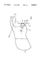
- FIG. 1 is a cross-sectional view perpendicular to the plane of a disc brake with an application device according to an exemplary embodiment of the invention
- FIG. 2 is an enlarged cross-sectional view taken along line 2--2 of FIG. 1;
- FIG. 3 is an elevational view of the application shaft in the disc brake according to FIGS. 1 and 2;
- FIG. 4 is a side view of the shaft of FIG. 3;
- FIG. 5 is an enlarged detail Z of FIG. 4.
- the disc brake illustrated in the drawings is a sliding-caliper disc brake, having a brake caliper 1 the two legs of which extend over a brake disc 2, in customary fashion. Brake linings 3, 4 disposed on lining supports 5 on both aides of the disc are guided and supported in a brake bracket (not shown) or in the housing of the caliper 1.
- the caliper 1 is mounted so as to be slidable in the direction perpendicular to the disc, with the aid of guide means (not shown in detail).
- the caliper 1 has an application mechanism 6 on one side for applying the brake.
- the application mechanism 6 is comprised essentially of a brake lever 7 which is connected to an application shaft 8 disposed parallel to the plane of the brake disc, a thrust piece 9 which can be slid within the caliper 1, and a thrust spindle 10 screwed into the center of the thrust piece 9 in the plane of the brake axis A of the application device 6.
- a thrust head 11 is coupled to the spindle 10, which thrust head abuts against the lining support 5.
- the thrust head 11 extends approximately over the entire width of the lining.
- the thrust piece 9 is guided on all sides in semicylindrical lateral guideways 25 in the caliper 1, with small bearing play.
- a cover 12 is affixed to the caliper 1, which cover provides a connection to a brake cylinder (not shown).
- the brake lever 7 mediates the connection between the brake cylinder (or a brake connecting rod, also not shown) and the application shaft 8.
- a support plate 14 is accommodated in or disposed in front of the cover 12, in the caliper 1, in a plane parallel to the brake disc 2. Plate 14 has a support surface 15 against which the application shaft 8 abuts.
- the support plate 14 may be segmented or of unit construction. Its length depends on the configuration of the application shaft 8, which will be described infra. According to FIGS. 2 and 3, a free throughgoing opening 16 is provided in the middle region of the application shaft 8, for axial disposition of the thrust spindle 10 (i.e. the thrust spindle 10 extends perpendicular to the brake disc but transversely to the axis of the application shaft 8).
- the application shaft 8 may be configured without a free throughgoing opening 16 but rather in a generally uninterrupted contour, so that the brake application may be accomplished via two thrust spindles 10 each of which is screwed onto a respective outer end of the thrust piece 9.
- the particularly compact structure of the application device enables provision of a void space 26 on the brake-disc side of the application shaft 8 and thus in the force-free region of the brake.
- This space may be used to house an adjusting device, e.g., of the type described in a related patent application of like date.
- the adjusting device may be installed as a pre-manufactured module. It is not exposed to appreciable stress (mechanical or thermal or with regard to contamination).
- FIGS. 3 and 4 show the contour of the application shaft 8.
- FIG. 5 is an enlarged view of detail Z.
- the shaft On the side of the application shaft 8 which is disposed toward the brake disc, the shaft has an approximately semicylindrical projection 17 with a radius R.
- the center P of the cylinder lies on the brake axis A.
- the shell surface of the projection 17 extends parallel to the rotational axis of shaft 8, which axis moves over the interval P1,P2--(see infra and FIG. 5) in correlation with the rotation of the application shaft 8.
- the projection 17 is rotatably mounted via an interposed antifriction bearing 18 (e.g. a roller and/or sliding bearing) in associated interior cylindrical surfaces 19 of the thrust piece 9. In this way a relatively large-surfaced contact contour is provided between these two parts for support on all sides and uniform transmission of thrust.
- the projection may be provided on element 9, with the (inner) cylindrical surface being provided on element 8; however, the above described configurations are preferred.
- the shell surface of a thrust ridge 20 disposed parallel to projection 17, which ridge abuts a support surface 15, is formed by a curve 21 which constitutes a succession of a plurality of curved segments (here two in number).
- the first segment I is a part of a circular arc with radius R1, around point P1 which point does not coincide with the point P.
- the second curved segment II which adjoins the first segment I is a part of a circular arc with radius R2, around point P2 which coincides neither with point P nor point P1.
- Radius R1 is less than radius R2.
- the radii R1 and R2, and the respective positions of points P1 and P2, are chosen such that the two arcs are tangent in a common boundary line B.
- the shell surface of the adjoining second curved segment II with the larger radius R2 rolls farther in the angular direction, or radially, downward from the boundary line B, on the support surface 15.
- intensified contact pressure of the surfaces which is present during the forceful excursion B is better borne by the greater radius R2.
- the principal result is that neither the eccentric nor the point P moves beyond the vertical 22 (i.e., the eccentric P1 does not move rightward of 22 and the rotational axis P does not move leftward of 22).
- the rolling segment in the angular direction (radially inward) via the larger radius R2 is longer for a given axial displacement of the thrust piece 9 than via the first rolling segment via the radius R1.
- the disposition of the thrust ridge 20 with respect to the support surface 15 of the brake caliper 1 affords another advantage as well, namely compensation for tolerances with respect to the antifriction bearings which tolerances are occasioned by manufacturing and assembly.
- the opposite configuration is possible, with the thrust ridge 20 on the support plate 14 and support surface 15 on the application shaft 8; however, the above described embodiment is preferred.
- the application mechanism (thrust piece, bearing, and application shaft) is pre-stressed in the direction toward the support surface 15, and thereby the brake lever 7 is pre-stressed against a caliper detent 24.
- FIG. 2 shows that the thrust ridge 20 is longer than the antifriction bearing 18. In this way the stresses on the ridge are comparable to the stresses on the bearings; also, optimal use of space in the caliper is enabled.
- the principle of brake application according to FIG. 1, particularly the configuration and bearing arrangement of the application shaft, may be adapted to a hydraulic disc brake with mechanical actuation when operated as a parking brake.
- the surface pressures against the caliper support are lower because the application forces are lower, and the courses he curved segments I and II may be reversed, with the larger radius coming first and then the smaller radius, to form a combined curve 21. This brings about a very precise linear application movement of the thrust piece 9.
Abstract
Description
Claims (20)
Applications Claiming Priority (2)
| Application Number | Priority Date | Filing Date | Title |
|---|---|---|---|
| DE4307019A DE4307019B4 (en) | 1993-03-05 | 1993-03-05 | Clamping device for a disc brake |
| DE4307019.1 | 1993-03-05 |
Publications (1)
| Publication Number | Publication Date |
|---|---|
| US5400875A true US5400875A (en) | 1995-03-28 |
Family
ID=6482075
Family Applications (1)
| Application Number | Title | Priority Date | Filing Date |
|---|---|---|---|
| US08/206,672 Expired - Lifetime US5400875A (en) | 1993-03-05 | 1994-03-07 | Brake application mechanism for a disc brake |
Country Status (3)
| Country | Link |
|---|---|
| US (1) | US5400875A (en) |
| EP (1) | EP0614024B1 (en) |
| DE (1) | DE4307019B4 (en) |
Cited By (16)
| Publication number | Priority date | Publication date | Assignee | Title |
|---|---|---|---|---|
| US5547048A (en) * | 1994-08-25 | 1996-08-20 | Perrot Bremsen Gmbh | Mechanism for disc brake |
| US5582273A (en) * | 1993-03-18 | 1996-12-10 | Knorr-Bremse Systeme Fuer Nutzfahrzeuge | Compressed-air disc brake |
| US5622240A (en) * | 1992-09-08 | 1997-04-22 | Knorr Bremse Systeme Fuer Nutzfahrzeuge | Compressed-air actuated disk brake |
| US5680912A (en) * | 1995-07-10 | 1997-10-28 | Perrot Bremsen Gmbh | Disc brake |
| US5697474A (en) * | 1995-04-24 | 1997-12-16 | Perrot Bremsen Gmbh | Disc brake with a seal between a brake caliper and an actuating apparatus of the disc brake |
| US5788022A (en) * | 1995-03-02 | 1998-08-04 | Perrot Bremsen Gmbh | Disc brake |
| US20030217898A1 (en) * | 2002-04-29 | 2003-11-27 | Paul Antony | Application device for a disk brake |
| US6766885B2 (en) * | 2000-04-03 | 2004-07-27 | Haldex Brake Products Ab | Brake mechanism |
| US20110147139A1 (en) * | 2008-07-04 | 2011-06-23 | Knorr-Bremse Systeme Fuer Nutzfahrzeuge Gmbh | Pneumatically Actuatable Disc Brake and Brake Cylinder |
| CN103221711A (en) * | 2010-11-26 | 2013-07-24 | 威伯科车轮制动有限公司 | Disk brake |
| WO2013167724A1 (en) * | 2012-05-11 | 2013-11-14 | Knorr-Bremse Systeme für Nutzfahrzeuge GmbH | Disc brake for a utility vehicle |
| US8845499B1 (en) | 2011-12-09 | 2014-09-30 | Donald Jeffrey Boatwright | Personal force resistance cable exercise device, force resistance assembly, and method of exercising |
| WO2015004696A1 (en) * | 2013-07-11 | 2015-01-15 | 株式会社Tbk | Disc brake device |
| US9700753B1 (en) | 2011-12-09 | 2017-07-11 | Donald Jeffrey Boatwright | Personal force resistance cable exercise device, force resistance assembly, and method of exercising |
| US10000987B2 (en) | 2013-02-21 | 2018-06-19 | National Oilwell Varco, L.P. | Blowout preventer monitoring system and method of using same |
| US10843029B2 (en) | 2011-12-09 | 2020-11-24 | Donald Jeffrey Boatwright | Cable exercise device and method |
Families Citing this family (16)
| Publication number | Priority date | Publication date | Assignee | Title |
|---|---|---|---|---|
| DE4416175A1 (en) | 1994-05-06 | 1995-11-09 | Perrot Bremsen Gmbh | Disc brake |
| SE505339C2 (en) † | 1994-10-24 | 1997-08-11 | Haldex Ab | Disc brake caliper |
| DE19515063C2 (en) † | 1995-04-27 | 2002-06-06 | Knorr Bremse Systeme | Disc brake for vehicles, in particular road vehicles |
| SE522332C2 (en) | 2000-05-31 | 2004-02-03 | Haldex Brake Prod Ab | Method of mounting a brake mechanism in a caliper and such caliper |
| SE516495C2 (en) | 2000-05-31 | 2002-01-22 | Haldex Brake Prod Ab | Brake mechanism and caliper for a disc brake |
| SE522395C2 (en) | 2000-05-31 | 2004-02-03 | Haldex Brake Prod Ab | Modular brake mechanism |
| DE10232961B4 (en) * | 2002-07-19 | 2007-06-14 | Wabco Perrot Bremsen Gmbh | Disc brake, in particular for land vehicles |
| DE10242397B3 (en) * | 2002-09-12 | 2004-03-18 | Haldex Brake Products Ab | Disk brake for vehicles, especially heavy goods vehicles comprises a caliper, a thrust element, a brake application device consisting of a rotating lever, and a rotation body |
| DE102005046003B4 (en) * | 2005-09-23 | 2016-08-25 | Bpw Bergische Achsen Kg | wheel brake |
| DE102005056065B3 (en) * | 2005-11-24 | 2007-08-23 | Knorr-Bremse Systeme für Nutzfahrzeuge GmbH | Disc brake, in particular for a commercial vehicle |
| DE102006003294A1 (en) * | 2006-01-23 | 2007-08-02 | Bpw Bergische Achsen Kg | disc brake |
| DE102006033254B3 (en) * | 2006-07-18 | 2007-09-13 | Wabco Radbremsen Gmbh | Disc brake for commercial vehicle, has friction damper provided for influencing vibration characteristics of brake and working between two components of brake, where components move relative to one another during clamping |
| DE102009013005C5 (en) * | 2009-03-13 | 2013-05-02 | Knorr-Bremse Systeme für Nutzfahrzeuge GmbH | Dual-piston disc brake |
| DE102013011657B4 (en) * | 2013-07-12 | 2016-08-25 | Knorr-Bremse Systeme für Nutzfahrzeuge GmbH | Disc brake for a commercial vehicle |
| DE102015101468A1 (en) | 2015-02-02 | 2016-08-04 | Bpw Bergische Achsen Kg | Disc brake for a commercial vehicle wheel |
| AT522087B1 (en) * | 2019-04-24 | 2020-08-15 | Greenbrakes Gmbh | BRAKE DEVICE |
Citations (6)
| Publication number | Priority date | Publication date | Assignee | Title |
|---|---|---|---|---|
| US3332521A (en) * | 1965-08-11 | 1967-07-25 | Bendix Corp | Closed loop type disc brake |
| US3830343A (en) * | 1972-12-12 | 1974-08-20 | Goodrich Co B F | Disc brake with adjustable cam operator and thrust distributer |
| US4109765A (en) * | 1975-04-02 | 1978-08-29 | The Bendix Corporation | Mechanically actuated disc brake |
| DE3411745A1 (en) * | 1984-03-30 | 1985-10-10 | Alfred Teves Gmbh, 6000 Frankfurt | Mechanical actuating device |
| WO1992007202A1 (en) * | 1990-10-17 | 1992-04-30 | Knorr-Bremse Ag | Disc brake for vehicles, especially road vehicles |
| EP0291071B1 (en) * | 1987-05-14 | 1992-07-22 | Knorr-Bremse Ag | Disc brake for vehicles |
Family Cites Families (2)
| Publication number | Priority date | Publication date | Assignee | Title |
|---|---|---|---|---|
| US4036329A (en) * | 1975-11-12 | 1977-07-19 | Rockwell International Corporation | Disc brake with rotary cam actuated reciprocating pistons |
| DE4217983A1 (en) * | 1991-06-26 | 1993-01-28 | Teves Gmbh Alfred | Actuator for vehicle disc brake - has cylindrical pressure bar with large contact pressure surfaces adjacent to actuating cam |
-
1993
- 1993-03-05 DE DE4307019A patent/DE4307019B4/en not_active Expired - Lifetime
-
1994
- 1994-03-03 EP EP94103230A patent/EP0614024B1/en not_active Expired - Lifetime
- 1994-03-07 US US08/206,672 patent/US5400875A/en not_active Expired - Lifetime
Patent Citations (6)
| Publication number | Priority date | Publication date | Assignee | Title |
|---|---|---|---|---|
| US3332521A (en) * | 1965-08-11 | 1967-07-25 | Bendix Corp | Closed loop type disc brake |
| US3830343A (en) * | 1972-12-12 | 1974-08-20 | Goodrich Co B F | Disc brake with adjustable cam operator and thrust distributer |
| US4109765A (en) * | 1975-04-02 | 1978-08-29 | The Bendix Corporation | Mechanically actuated disc brake |
| DE3411745A1 (en) * | 1984-03-30 | 1985-10-10 | Alfred Teves Gmbh, 6000 Frankfurt | Mechanical actuating device |
| EP0291071B1 (en) * | 1987-05-14 | 1992-07-22 | Knorr-Bremse Ag | Disc brake for vehicles |
| WO1992007202A1 (en) * | 1990-10-17 | 1992-04-30 | Knorr-Bremse Ag | Disc brake for vehicles, especially road vehicles |
Cited By (21)
| Publication number | Priority date | Publication date | Assignee | Title |
|---|---|---|---|---|
| US5622240A (en) * | 1992-09-08 | 1997-04-22 | Knorr Bremse Systeme Fuer Nutzfahrzeuge | Compressed-air actuated disk brake |
| US5582273A (en) * | 1993-03-18 | 1996-12-10 | Knorr-Bremse Systeme Fuer Nutzfahrzeuge | Compressed-air disc brake |
| US5547048A (en) * | 1994-08-25 | 1996-08-20 | Perrot Bremsen Gmbh | Mechanism for disc brake |
| US5788022A (en) * | 1995-03-02 | 1998-08-04 | Perrot Bremsen Gmbh | Disc brake |
| US5697474A (en) * | 1995-04-24 | 1997-12-16 | Perrot Bremsen Gmbh | Disc brake with a seal between a brake caliper and an actuating apparatus of the disc brake |
| US5680912A (en) * | 1995-07-10 | 1997-10-28 | Perrot Bremsen Gmbh | Disc brake |
| US6766885B2 (en) * | 2000-04-03 | 2004-07-27 | Haldex Brake Products Ab | Brake mechanism |
| EP1269039B1 (en) * | 2000-04-03 | 2006-08-30 | Haldex Brake Products AB | Brake mechanism |
| US20030217898A1 (en) * | 2002-04-29 | 2003-11-27 | Paul Antony | Application device for a disk brake |
| US7506732B2 (en) * | 2002-04-29 | 2009-03-24 | Wabco Perrot Bremsen Gmbh | Application device for a disk brake |
| US20110147139A1 (en) * | 2008-07-04 | 2011-06-23 | Knorr-Bremse Systeme Fuer Nutzfahrzeuge Gmbh | Pneumatically Actuatable Disc Brake and Brake Cylinder |
| US8286759B2 (en) * | 2008-07-04 | 2012-10-16 | Knorr-Bremse Systeme Fuer Nutzfahrzeuge Gmbh | Pneumatically actuatable disc brake and brake cylinder |
| CN103221711A (en) * | 2010-11-26 | 2013-07-24 | 威伯科车轮制动有限公司 | Disk brake |
| CN103221711B (en) * | 2010-11-26 | 2016-02-24 | 威伯科车轮制动有限公司 | Disk type braker |
| US8845499B1 (en) | 2011-12-09 | 2014-09-30 | Donald Jeffrey Boatwright | Personal force resistance cable exercise device, force resistance assembly, and method of exercising |
| US9498666B1 (en) | 2011-12-09 | 2016-11-22 | Donald Jeffrey Boatwright | Personal force resistance cable exercise device, force resistance assembly, and method of exercising |
| US9700753B1 (en) | 2011-12-09 | 2017-07-11 | Donald Jeffrey Boatwright | Personal force resistance cable exercise device, force resistance assembly, and method of exercising |
| US10843029B2 (en) | 2011-12-09 | 2020-11-24 | Donald Jeffrey Boatwright | Cable exercise device and method |
| WO2013167724A1 (en) * | 2012-05-11 | 2013-11-14 | Knorr-Bremse Systeme für Nutzfahrzeuge GmbH | Disc brake for a utility vehicle |
| US10000987B2 (en) | 2013-02-21 | 2018-06-19 | National Oilwell Varco, L.P. | Blowout preventer monitoring system and method of using same |
| WO2015004696A1 (en) * | 2013-07-11 | 2015-01-15 | 株式会社Tbk | Disc brake device |
Also Published As
| Publication number | Publication date |
|---|---|
| DE4307019A1 (en) | 1994-09-08 |
| EP0614024A1 (en) | 1994-09-07 |
| DE4307019B4 (en) | 2006-06-14 |
| EP0614024B1 (en) | 1996-09-04 |
Similar Documents
| Publication | Publication Date | Title |
|---|---|---|
| US5400875A (en) | Brake application mechanism for a disc brake | |
| JP3881710B2 (en) | Disc brake actuator | |
| US5433298A (en) | Actuating mechanism for a sliding-caliper disc brake | |
| US7506732B2 (en) | Application device for a disk brake | |
| US8028810B2 (en) | Disk brake | |
| KR0158896B1 (en) | Disc brake for vehicles especially road vehicles | |
| US7182185B2 (en) | Disk brake comprising an adjuster module | |
| RU2429393C2 (en) | Vehicle clamp brake | |
| RU2328635C2 (en) | Braking mechanism for disk brake | |
| US8707812B2 (en) | Ball screw drive having an axially supported threaded spindle | |
| US20120090418A1 (en) | Ball screw with circumferential stop | |
| KR20010093284A (en) | Compact actuator | |
| JP2008522106A (en) | Caliper for disc brake | |
| US20210062899A1 (en) | Segmented spring for a ball screw | |
| JP2005299929A (en) | Electromechanical disc brake | |
| JP2013540246A (en) | Disc brake having a latch for locking the conversion cartridge by the latch | |
| JP3091486B2 (en) | Actuator for automotive brakes | |
| KR20180042420A (en) | Disc brakes for vehicles, especially commercial vehicles | |
| CN101313161A (en) | Electromechanical zero backlash brake | |
| JP2000145845A (en) | Vehicle brake actuating device | |
| US8607939B2 (en) | Braking device, in particular for a motor vehicle | |
| JP2005016728A (en) | Disc brake with self-boosting action | |
| US7007775B2 (en) | Screw actuator with a fixed nut | |
| US7896141B2 (en) | Disc brake with electrically operated adjustment device | |
| JP4219921B2 (en) | Disc brake actuator with parking operation mechanism |
Legal Events
| Date | Code | Title | Description |
|---|---|---|---|
| AS | Assignment |
Owner name: PERROT BREMSEN GMBH, GERMANY Free format text: ASSIGNMENT OF ASSIGNORS INTEREST;ASSIGNORS:ANTHONY, PAUL;BAUMGARTNER, RAINER;BIELAWSKI, ANDRZEJ;AND OTHERS;REEL/FRAME:007029/0973 Effective date: 19940303 |
|
| STCF | Information on status: patent grant |
Free format text: PATENTED CASE |
|
| FEPP | Fee payment procedure |
Free format text: PAYOR NUMBER ASSIGNED (ORIGINAL EVENT CODE: ASPN); ENTITY STATUS OF PATENT OWNER: LARGE ENTITY |
|
| FPAY | Fee payment |
Year of fee payment: 4 |
|
| FPAY | Fee payment |
Year of fee payment: 8 |
|
| FPAY | Fee payment |
Year of fee payment: 12 |
|
| AS | Assignment |
Owner name: WABCO PERROT BREMSEN GMBH, GERMANY Free format text: CHANGE OF NAME;ASSIGNOR:PERROT BREMSEN GMBH;REEL/FRAME:034780/0762 Effective date: 19970325 |
|
| AS | Assignment |
Owner name: WABCO RADBREMSEN GMBH, GERMANY Free format text: CHANGE OF NAME;ASSIGNOR:WABCO PERROT BREMSEN GMBH;REEL/FRAME:034807/0290 Effective date: 20040327 |
|
| AS | Assignment |
Owner name: WABCO EUROPE BVBA, BELGIUM Free format text: ASSIGNMENT OF ASSIGNORS INTEREST;ASSIGNOR:WABCO RADBREMSEN GMBH;REEL/FRAME:034818/0939 Effective date: 20140904 |