US539945A - Drill-making machine - Google Patents
Drill-making machine Download PDFInfo
- Publication number
- US539945A US539945A US539945DA US539945A US 539945 A US539945 A US 539945A US 539945D A US539945D A US 539945DA US 539945 A US539945 A US 539945A
- Authority
- US
- United States
- Prior art keywords
- shaft
- clutch
- cutter
- drill
- secured
- Prior art date
- Legal status (The legal status is an assumption and is not a legal conclusion. Google has not performed a legal analysis and makes no representation as to the accuracy of the status listed.)
- Expired - Lifetime
Links
- 230000003028 elevating effect Effects 0.000 description 7
- 230000007246 mechanism Effects 0.000 description 6
- 238000010276 construction Methods 0.000 description 4
- 230000001965 increasing effect Effects 0.000 description 3
- 230000003247 decreasing effect Effects 0.000 description 2
- 230000000994 depressogenic effect Effects 0.000 description 2
- 230000005484 gravity Effects 0.000 description 1
- 238000000034 method Methods 0.000 description 1
- 239000000126 substance Substances 0.000 description 1
Images



Classifications
-
- B—PERFORMING OPERATIONS; TRANSPORTING
- B23—MACHINE TOOLS; METAL-WORKING NOT OTHERWISE PROVIDED FOR
- B23C—MILLING
- B23C3/00—Milling particular work; Special milling operations; Machines therefor
- B23C3/28—Grooving workpieces
- B23C3/32—Milling helical grooves, e.g. in making twist-drills
-
- Y—GENERAL TAGGING OF NEW TECHNOLOGICAL DEVELOPMENTS; GENERAL TAGGING OF CROSS-SECTIONAL TECHNOLOGIES SPANNING OVER SEVERAL SECTIONS OF THE IPC; TECHNICAL SUBJECTS COVERED BY FORMER USPC CROSS-REFERENCE ART COLLECTIONS [XRACs] AND DIGESTS
- Y10—TECHNICAL SUBJECTS COVERED BY FORMER USPC
- Y10T—TECHNICAL SUBJECTS COVERED BY FORMER US CLASSIFICATION
- Y10T409/00—Gear cutting, milling, or planing
- Y10T409/30—Milling
- Y10T409/300056—Thread or helix generating
- Y10T409/300168—Thread or helix generating with means to regulate operation by use of templet, card, or other replaceable information supply
- Y10T409/30028—Thread or helix generating with means to regulate operation by use of templet, card, or other replaceable information supply to regulate cutting depth [e.g., relief, taper, etc.]
-
- Y—GENERAL TAGGING OF NEW TECHNOLOGICAL DEVELOPMENTS; GENERAL TAGGING OF CROSS-SECTIONAL TECHNOLOGIES SPANNING OVER SEVERAL SECTIONS OF THE IPC; TECHNICAL SUBJECTS COVERED BY FORMER USPC CROSS-REFERENCE ART COLLECTIONS [XRACs] AND DIGESTS
- Y10—TECHNICAL SUBJECTS COVERED BY FORMER USPC
- Y10T—TECHNICAL SUBJECTS COVERED BY FORMER US CLASSIFICATION
- Y10T409/00—Gear cutting, milling, or planing
- Y10T409/30—Milling
- Y10T409/300056—Thread or helix generating
- Y10T409/300504—Plural cutters or work holders
Definitions
- the object of my invention is to provide a machine by means of which an improved twist drill may be manufactured, the machine combining means for producing a twist drill with a groove of any desired'pitch and depth, and
- my invention consists in the details of the several parts making up the machine as 'a whole and in the combination of such parts as more particularly hereinafter described and pointed. out in the claims.
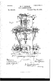
- Figure 1 is a view in front elevation of'my improved machine, with the hand-wheel shaft cut in section.
- Fig. 2 is a view in rear elevation of the machine.
- Fig. 3 is a view in side elevation of the machine with parts broken away to show construction.
- Fig. 4 is a top or plan view of the machine, one side being cut in section through the axis of the driving-worm shaft and of the cutter-spindle.
- Fig. 5 is a perspective view of the lower part of the machine.
- Fig. 6 is a detail top view in section through the cutter-head in the axis of the driving-worm shaft and of the cutter-spindle, showing the manner of pivoting said cutterhead to the top slide and the relation of the cutter and pivot.
- FIG. 7 is a detail end view of the top slide and cutter-head, showing the means for giving vertical-movement to the latter.
- Fig. 8 is a detail front view insection through the pivot of the cutter-head, showing the relation of the cutter to said pivot.
- Fig. 9 is a detail front view of the web-slides for varyingthe distance between the cutters.
- Fig. 10 is a detail view in section through one of the web-slides, showing its contact with the cutter-head slide.
- Fig. 11 is a. view in horizontal section through the machine on a line just above the clutch-shaft, looking down.
- Fig. 12 is a like view on a line between the clutch-shaft and equalizing-shaft and immediately above the latter.
- Fig. 13 is alike view on a line just underneath the casings for the point to shank, the groove decreasing in depth and the Web consequently increasing in. thickness from point to shank, and the within de-- scribed machine is particularly adapted for producing that form
- the machine means for holding the drill blank, for rotating it, and for cutting grooves in diametrically opposite sides of the blank, the cutters during the process of cutting changing their angle of inclination with respect to the axis of the drill blank, which has a lengthwise feeding motion across thecutters.
- the cutters are arranged on diametrically opposite sides of the blank and are movable directly outward and away from the axis of the drill blank for the purpose of decreasing the depth ofthe groove and increasing the thickness of the Web, the latter being that part of the drill included between the bottom'surfaces of the grooves.
- A denotes the standard; B, the base of the machine; B, the side posts; .13 the top piece; B the cross-piece, and B the bottom piece.
- This worm gear 01 is secured to an interior screw threaded sleeve that extends upward and has a bearing in the top piece B ahd to the upper end of this sleeve is secured the gear a by means of'which, through a series of gears of any desired number, movement is imparted to the vertical shaft a
- a bevel gear is also secured to the under side of the worm gear a and is in mesh with the bevel gear a supported on the shaft bearing the hand wheel a
- the sleeve to which this worm gear a is secured, or of which it forms a part, is screw threaded on its interior surface and fits the screw threaded portion 1) of the blank holding shaft 1).
- the shaft a bears on its lower end a bevel gear a in mesh with a clutch-shaft driving gear 0' secured'to the clutch-shaft c.
- This clutch shaft 0 bears a worm c that is in mesh with the worm gear 19 secured to the blank holding shaft 1).
- the clutch shaft 0 has a comparatively slow rotation, and through the medium of worms and gears just described a rotary motion is imparted .to the blank holding shaft 1) andconsequently to the blank held therein at its lower end.
- a more detailed de- -scri p'tion of this part of the machine has been omitted for the reason that it forms the subject matter of Letters Patent to myself, dated a with the equalizing-shaft-driving-gears c
- One end of each of the releasing yokes d is secured to a clutch-sleeve in such manner as to allow the latter to rotate freely but have no lengthwise movement therein.
- the other ends of these sleeves are secured to the releasing rods d that are located in casings B in such manner as to have a free lengthwise movement therein.
- the equalizing shaft bearings e are pivoted upon the releasing rod casings B or upon the side parts of the frame of the machine in such manner as to have a movement toand from the clutch shaft 0 and in the outer ends of these equalizing shaft bearings e is mounted the equalizing shaft (1 to which are secured the equalizing shaft gears d in mesh With the equalizing shaft driving gears 0
- On the inner ends of the releasing rods 01 are pivoted the links (1 the opposite ends of these links being pivoted to the slide 61 located in the slideway on the cross-piece B
- To this slide 01 is also pivoted one end of the slide operating link d the opposite end of this link being secured to the slide operating rod (1 that extends through the cross-piece B to the front of the machine, the mechanism above described being located on the rear of the machine.
- the clutch hand lever To the opposite end of the slide operating rod (i at the front of the machine is secured the clutch hand lever (1 the inner end ofthislever being adapted to engage the latch 01 pivoted to the cross-piece B
- the clutch hand lever is provided on its upper side with a cam extension 11 of such length as to constantly engage the latch d when the hook on the lower end of the latter is forced out of engagement with the clutch hand lever and the latter is forced downward under the impulse of the spring plunger d located in a socket on the machine, a spring tending to force the plunger normally downward.
- This spring plunger operates to force the slide (i downward upon the release of the clutch hand lever from engagement with the latch as by raising the outer end of the latter the clutch parts are held out of engagement when the slide at is at the upper limit of its play the central pivot of the links being located either in alignment with the axes of the releasing rods d or at a point above that line.
- This equalizing shaft d connects the clutch worms 0 through the medium of the gears c compelling both clutch worms to turn together, these clutch worms being in engagement with the elevating shafts E that lift or depress the cutter heads K.
- top slides fare located the bearings f':for the elevating Worm shafts 6 and there are also secured to said top slides, preferably integral therewith, the head supportsf
- the top slidesf are adjustably secured to the intermediate slides by means of bolts passing through slotted openings f in the'top slides, the top slides being adjustable on the intermediate slides in a line lengthwise of the cutter spindle.
- Each intermediate slide 9 has a dove-tailed projection on its under side adapted to fit a dove-tailed groovein the upper part of the bottom slides 71.
- These bottom slides have also located on their under sides dove-tailed grooves adapted to, receive of the slide bases, the latter being secured to the base B.
- the bottom slides are movable on the slide bases laterally of the machine, and theintermediate slides are movable on the bottom slides also laterally of the machine,
- the cutter heads K have on their inner ends sockets is within which fits one end of the cutter is the screw threaded openingk for the reception of the retaining screwsf this construction of the joints affording a means of securing the parts together that prevents any rocking or sidewise movement whatever of the one part upon the other.
- These cutterheads K are provided with projections or bearings 78, it for the cutter spindles Z.
- cutter spindles Z areprovidedon their lower ends with any suitable means of attachment thereto of the cutters Z,preferably being screw threaded, and the cutters are secured to the spindles by means of nuts fitting the ends of the spindles.
- Each cutter spindle has abevel portion Z fitting within the bevel socket in 1 the cutter bearing and on the upper side of this bearing 10 and secured to the spindle as by a key is a collar Z and on a threaded portion of the spindle adjacent to this collar a lock nut Z.
- the bearings 10 are sleeves'l the lowerends of which are screw threaded and bear nuts Z these several collars and nuts just described afiording a means of taking up any wear and preventing the spindle from any lateral or longitudinal movement within the bearings.
- the worm gear ZZ-the spindle drivers'Z fitting upon the end of the spindle land being collar m fitting over theend of the driving shaft and secured to thegear as by means of screws passing through the former intothe latter, the collar in turn being secured to the driving shaft by means of a'key or of a pin passing through the parts.
- the front edges of the cutter head supports f are formed inrthe arc of a circle struck from the center of the cutter head joints f and aprojection 70 extends outward from each of the cutter heads a distance equal to the thickness of thecutter head supports f, the edge of this projection adjacent to the head supports being formed in the same are of a circle as the edge of said head support.
- Ele vating head gibs k are secured to the'pr'ojections 1& insuch manner as to extend some distance inward along the head supports f on IlO
- To the driving shafts n are the side opposite from the body of the cutter heads K.
- the web yoke 0 is secured to the blank holding shaft 19 and its Opposite ends extend on opposite sides of the posts B.
- Web slides 0 project downward from each end of said web yokes through openings in the top slides f, these web slides having their upper ends inclined outward to give to the top slidesf a movement away from and toward the blank feeding shaft as the web yoke 0 moves downward and upward.
- a vertical shipping rod is also secured to one end of the web yoke and extends upward to engage the swinging bracket a to throw the mechanism thereon out of engagement with the other parts of the machine and stop its operation at predetermined positions of the web yoke 0.
- a clutch disengaging rodp is adjustably secured in a socket in the front of the web yoke 0, the upper end of this rod having adjustably secured thereto the engaging and disengaging rod yoke p, and to this yoke is secured the engaging rod 19 the upper endof whichbears a trip 19 adapted to engage a pin 61 on the latch d.
- An important feature of my invention consists in the combination of mechanisms and means whereby the angular relation of the axis of the drill blank to the plane of the cutter, or to that line which has been described as the circumferential axis of the cutter, may be changed.
- the result of the change of the angular relation of the plane of the cutter to the axis of the drill blank enables the width of the groove to be maintained .as the groove is being out in the substance of the drill blank, and while the cutters are drawn back to give increased thickness of web.
- the clutch disengaging rodp cutter supported in operative relation thereto, means for automatically swinging the cutter on a diametrical axis, and means for automatically rotating the cutter on a circumferential axis simultaneously with its movement on the diametrical axis, all substantially as described.
- a frame supporting therein a blank holding shaft, means for operating said shaft, a cutter head pivoted transversely of the axis of the blank holding shaft, means for automatically swinging the cutter head on its pivot, the cutter spindle borne in the cutter head, and means for automatically rotating the spindle simultaneously with the swinging movement of the cutter head, all substantially as described.
- aframe supporting therein a blank holding shaft, means for operating said shaft, a cutter head pivoted transversely of the axis of the blank holding shaft, means for automatically swinging the cutter head on its pivot, the cutter spindle borne in the cutter head to swing therewith, the spindle.
- driving shaft borne in a swinging frame and in engagement with the cutter spindle, the swinging frame, and means for rotating the spindle driving shaft simultaneously with the swing ing movement of the cutter head, all substantially as described.
- a frame supporting therein a blank holding shaft, means for operating said shaft, a cutter head pivoted transversely of the axis of the blank holding shaft, means for automatically swinging the cutter head on its pivot, the cutter spindle borne in the cutter head to swing therewith, a cross shaft borne on the cutter head in operative engagement with the cutter spindle, the spindle driving shaft borne in a swinging frame and in opertive engagement with the cross shaft on the pivots, the cutter spindles borne in the cutter heads to swing therewith, the spindle driving shafts in operative engagement with the cutter spindles, and means for rotating the driving shafts simultaneously with the swinging movementof the cutter heads, all substantially as described.
- the clutch shaft and means operatively connecting said shaft with said cutter heads to swing them on their pivots, the clutch devices interposed between the clutch shaft and the swinging cutter heads, and means for automatically engaging and disengaging said clutch devices in the operation of the machine, all substantially as described.
- a clutch loosely mounted on the shaft, a clutch sleeve secured to, the shaft to rotate therewith but having a free longitudinal movement thereon and adapted to engage the clutch, the releasing rods in operative engagement with the clutch sleeve, the operating rod in engagement with the releasing rods, mechanism for holding the releasing rods at-either limitof their play, and trip devices borne on moving parts of the machine and adapted to engage and disengage the clutch devices, all substantially as described.
- the clutch devices borne on the clutch shaft and adapted to engage and disengage said shaft from operating parts of the machine, the releasing rods in engagement with the clutch device, the clutch hand lever connected to the releasing rods, the latch adapted to engage and disengage the hand lever, the'web yoke, the clutch disengaging rod adjustably secured to the yoke, the engaging and disengaging yoke adjustably secured to the disengaging rod, the engaging rod secured to the engaging and disengaging yoke and provided with a trip adapted to engage the latch to force it out of engagement with the hand lever, and means for rotating the clutch shaft, all substantially as described.
- a movable blank holding device a cutter with its periphery supported in operative cutting relation to the path of movement of a drill blank secured in the holder, and means for automatically changing the angular relation of the plane of the cutter and the axis of the drill blank, all substantially as described.
- a movable blank holding device In combination in a twist drill cutting machine, a movable blank holding device, a cutter With its periphery adjustably supported in operative cutting relation to the path of movement of the drill blank, and means for automatically changing the angular relation of the plane of the cutter and. the axis of the drill blank, all substantially as described.
Landscapes
- Engineering & Computer Science (AREA)
- Mechanical Engineering (AREA)
- Drilling And Boring (AREA)
Description
(No Model.) 6 Sheets-Sheet 1.
M. G. JOHNSON. DRILL MAKING MACHINE.
No. 559,945. Patented May 28, 1895.
fl AX/ww aw: QS/VVVM/VVO'W mmwwm w (No Mode 1.) 6 Sheets-Sheet 2.
M. G. JOHNSON. DRILL MAKING MACHINE.
No. 539.945. Patented May 28, 1895.
s sheets-sheet 3.
Patented May 28, 1895.
(No Model.)
M. G. JOHNSON. DRILL MAKING MAGHINEL N0. 539,945.
CR5 co, murmur my wasumomu. 0.1:.
e Sheets-Sheet 5.
M. G. JOHNSON.
DRILL MAKING MACHINE.
Patented May 28; 1895.
. (No Model.)
M flaw (No Model.) 6 Sheets8heet a.
M. 0. JOHNSON. DRILL MAKING MACHINE.
No. 539,945. Patented May 28, 1895.
WM 2 I Q Cfloaea /0/// w01 o azanjwm UNITED STATES PATENT OFFICE.
MOSES C. JOHNSON, OF HARTFORD,-ASSIGNOR TO THE T. & B. TOOL COM- PANY', OF DANBURY, CONNECTICUT.
DRILL-MAKING MACHINE.
SPECIFICATION forming part of Letters Patent No. 539,945, dated. May as, 1895.
Application filed January 23,1894. serial No. 497,837. (No lllOdelJ' To aZZ whom it may concern.-
Be it known that I, Mosns O. JOHNSON, of Hartford, in the county of Hartford and State of Connecticut, have invented certain new and usefulImprovements in Drill-MakingMachines, of which the following is a full, clear,
and exact description, whereby any one skilled in the art can make and use the same. 4
The object of my invention is to provide a machine by means of which an improved twist drill may be manufactured, the machine combining means for producing a twist drill with a groove of any desired'pitch and depth, and
consequent thickness of web.
To this end my invention consists in the details of the several parts making up the machine as 'a whole and in the combination of such parts as more particularly hereinafter described and pointed. out in the claims.
Referring to the drawings, Figure 1 is a view in front elevation of'my improved machine, with the hand-wheel shaft cut in section. Fig. 2 is a view in rear elevation of the machine. Fig. 3 is a view in side elevation of the machine with parts broken away to show construction. Fig. 4: is a top or plan view of the machine, one side being cut in section through the axis of the driving-worm shaft and of the cutter-spindle. Fig. 5 is a perspective view of the lower part of the machine. Fig. 6 is a detail top view in section through the cutter-head in the axis of the driving-worm shaft and of the cutter-spindle, showing the manner of pivoting said cutterhead to the top slide and the relation of the cutter and pivot. Fig. 7 is a detail end view of the top slide and cutter-head, showing the means for giving vertical-movement to the latter. Fig. 8 is a detail front view insection through the pivot of the cutter-head, showing the relation of the cutter to said pivot. Fig. 9 is a detail front view of the web-slides for varyingthe distance between the cutters. Fig. 10 is a detail view in section through one of the web-slides, showing its contact with the cutter-head slide. Fig. 11 is a. view in horizontal section through the machine on a line just above the clutch-shaft, looking down. Fig. 12 is a like view on a line between the clutch-shaft and equalizing-shaft and immediately above the latter. Fig. 13 is alike view on a line just underneath the casings for the point to shank, the groove decreasing in depth and the Web consequently increasing in. thickness from point to shank, and the within de-- scribed machine is particularly adapted for producing that form of twist drill.
There is embodied in the machine means for holding the drill blank, for rotating it, and for cutting grooves in diametrically opposite sides of the blank, the cutters during the process of cutting changing their angle of inclination with respect to the axis of the drill blank, which has a lengthwise feeding motion across thecutters. The cutters are arranged on diametrically opposite sides of the blank and are movable directly outward and away from the axis of the drill blank for the purpose of decreasing the depth ofthe groove and increasing the thickness of the Web, the latter being that part of the drill included between the bottom'surfaces of the grooves. The mere withdrawal of the mills would decrease the depth of the grooves, butwould at v the same time decrease the width, and in or der to maintain a substantially uniform width of groove from point to shank, which is an important feature, the cutter is caused to change its angular position with reference to the axis of the drill and in this manner maintain the required uniformity of width 'of groove along its whole/length. When the cutter is in contact with'the blank in the operation of cutting, a line extended at right angles to the axis of the blank and diametrically through the cutter will represent the axis on which the cutter moves when changing its angular relation to the drill, and it is evident that a pivotal point of support for the cutter in prolongation of this axial line must be provided. One form of providing this change in too the angular relation of the cutter with respect to the axis of the drill during the cutting of the groovesis embodied and illustrated in the within application,
In the drawings forming a part hereof the letter A denotes the standard; B, the base of the machine; B, the side posts; .13 the top piece; B the cross-piece, and B the bottom piece.
Near the upper end of the posts B is supported a swinging bracket a pivoted to one of the side posts, and on this swinging bracket is supported a fixed stud a bearing a pulley a that'is driven by means of a belt from any suitable source of power and by means of which rotary movement is imparted through means of intermeshing gears to the wormshaft a bearing a worm in mesh with a worm gear a. This worm gear 01 is secured to an interior screw threaded sleeve that extends upward and has a bearing in the top piece B ahd to the upper end of this sleeve is secured the gear a by means of'which, through a series of gears of any desired number, movement is imparted to the vertical shaft a A bevel gear is also secured to the under side of the worm gear a and is in mesh with the bevel gear a supported on the shaft bearing the hand wheel a The sleeve to which this worm gear a is secured, or of which it forms a part, is screw threaded on its interior surface and fits the screw threaded portion 1) of the blank holding shaft 1).
The rotation of the worm gear a and consequently the interior screw threaded sleeve, above referred to, imparts to the blank holding shaft 1) a vertical movement through the medium of the screw threaded part b of said shaft fitting the interior screwthre'aded sleeve. The shaft a bears on its lower end a bevel gear a in mesh with a clutch-shaft driving gear 0' secured'to the clutch-shaft c. This clutch shaft 0 bears a worm c that is in mesh with the worm gear 19 secured to the blank holding shaft 1). The clutch shaft 0 has a comparatively slow rotation, and through the medium of worms and gears just described a rotary motion is imparted .to the blank holding shaft 1) andconsequently to the blank held therein at its lower end. A more detailed de- -scri p'tion of this part of the machine has been omitted for the reason that it forms the subject matter of Letters Patent to myself, dated a with the equalizing-shaft-driving-gears c One end of each of the releasing yokes d is secured to a clutch-sleeve in such manner as to allow the latter to rotate freely but have no lengthwise movement therein. The other ends of these sleeves are secured to the releasing rods d that are located in casings B in such manner as to have a free lengthwise movement therein. The equalizing shaft bearings e are pivoted upon the releasing rod casings B or upon the side parts of the frame of the machine in such manner as to have a movement toand from the clutch shaft 0 and in the outer ends of these equalizing shaft bearings e is mounted the equalizing shaft (1 to which are secured the equalizing shaft gears d in mesh With the equalizing shaft driving gears 0 On the inner ends of the releasing rods 01 are pivoted the links (1 the opposite ends of these links being pivoted to the slide 61 located in the slideway on the cross-piece B To this slide 01 is also pivoted one end of the slide operating link d the opposite end of this link being secured to the slide operating rod (1 that extends through the cross-piece B to the front of the machine, the mechanism above described being located on the rear of the machine. To the opposite end of the slide operating rod (i at the front of the machine is secured the clutch hand lever (1 the inner end ofthislever being adapted to engage the latch 01 pivoted to the cross-piece B The clutch hand lever is provided on its upper side with a cam extension 11 of such length as to constantly engage the latch d when the hook on the lower end of the latter is forced out of engagement with the clutch hand lever and the latter is forced downward under the impulse of the spring plunger d located in a socket on the machine, a spring tending to force the plunger normally downward. This spring plunger operates to force the slide (i downward upon the release of the clutch hand lever from engagement with the latch as by raising the outer end of the latter the clutch parts are held out of engagement when the slide at is at the upper limit of its play the central pivot of the links being located either in alignment with the axes of the releasing rods d or at a point above that line.
It is obvious that the cutter heads K, hereinafter referred to, hearing the cuttersshould be maintained in the same relative position and lifted or depressed simultaneously in order to enable a drill blank to be equally cut on each side, and the object of the construction of the equalizing shaft above described is to enable this result to be attained. This equalizing shaft d connects the clutch worms 0 through the medium of the gears c compelling both clutch worms to turn together, these clutch worms being in engagement with the elevating shafts E that lift or depress the cutter heads K. If the clutch worms 0' were not thus connected, when the clutch parts are thrown out of engagement the clutch worms would be loose on the shaft and a jar or other cause would be liable to rotate the same throwing the cutter head connected thereto out of its relative position with'the opposite cutter head, and the construction above described obviates such a fault.
IIO
's head joints f and centrally of this socket k two sections to rotate together but to have a t the dove-tailed projection on the upper side sliding movement one within the other, the lower end of the extensible section e 1 being secured to the elevating worm shafts e by means of a ball and socket joint, as above described. These elevating worm shafts bear elevating worms 6*, in mesh with a segmental gear 70 located on the elevating head-hereinafter described.
On the top slides fare located the bearings f':for the elevating Worm shafts 6 and there are also secured to said top slides, preferably integral therewith, the head supportsf The top slidesf are adjustably secured to the intermediate slides by means of bolts passing through slotted openings f in the'top slides, the top slides being adjustable on the intermediate slides in a line lengthwise of the cutter spindle. Each intermediate slide 9 has a dove-tailed projection on its under side adapted to fit a dove-tailed groovein the upper part of the bottom slides 71. These bottom slides have also located on their under sides dove-tailed grooves adapted to, receive of the slide bases, the latter being secured to the base B. The bottom slides are movable on the slide bases laterally of the machine, and theintermediate slides are movable on the bottom slides also laterally of the machine,
the several slides being provided with intermeshing screws and nuts for securing anydev adjustments of the slides one upon the other i may be secured. I
In the head supports f are bevel openings within which are located thecutter head joints f extending beyond the surface of the head supports and provided with central holes for the reception of the retaining screws f The cutter heads K have on their inner ends sockets is within which fits one end of the cutter is the screw threaded openingk for the reception of the retaining screwsf this construction of the joints affording a means of securing the parts together that prevents any rocking or sidewise movement whatever of the one part upon the other. These cutterheads K are provided with projections or bearings 78, it for the cutter spindles Z. These cutter spindles Z areprovidedon their lower ends with any suitable means of attachment thereto of the cutters Z,preferably being screw threaded, and the cutters are secured to the spindles by means of nuts fitting the ends of the spindles. Each cutter spindle has abevel portion Z fitting within the bevel socket in 1 the cutter bearing and on the upper side of this bearing 10 and secured to the spindle as by a key is a collar Z and on a threaded portion of the spindle adjacent to this collar a lock nut Z. In the bearings 10 are sleeves'l the lowerends of which are screw threaded and bear nuts Z these several collars and nuts just described afiording a means of taking up any wear and preventing the spindle from any lateral or longitudinal movement within the bearings. To the cutter spindle l is secured the worm gear ZZ-the spindle drivers'Z fitting upon the end of the spindle land being collar m fitting over theend of the driving shaft and secured to thegear as by means of screws passing through the former intothe latter, the collar in turn being secured to the driving shaft by means of a'key or of a pin passing through the parts.
On the base B are secured swinging frame basesn within which are pivoted the swinging frames 12', the npperl ends of the swinging frames branching outward and forming bearings for the driving shafts n On these driving shafts n are secured the driving gears n in mesh with the spindle driving gears m on the spindle driving shafts m. Yokes m are secured to the shafts 'n and on. respectively in such manner as to allow the shafts to rotate freely therein, the object of the yokes being to keep the gears m and n continually in'mesh with each other, the'swinging frames n allowing the gears to move to or away from the machine as the cutter heads are elevated or depressed. secured the pulleys n adapted to receive a belt extending from any suitable sourceof power and fur'nishingmeans for driving the cutter spindles and cutters attached thereto.
The front edges of the cutter head supports f are formed inrthe arc of a circle struck from the center of the cutter head joints f and aprojection 70 extends outward from each of the cutter heads a distance equal to the thickness of thecutter head supports f, the edge of this projection adjacent to the head supports being formed in the same are of a circle as the edge of said head support. Ele vating head gibs k are secured to the'pr'ojections 1& insuch manner as to extend some distance inward along the head supports f on IlO To the driving shafts n are the side opposite from the body of the cutter heads K.
The web yoke 0 is secured to the blank holding shaft 19 and its Opposite ends extend on opposite sides of the posts B. Web slides 0 project downward from each end of said web yokes through openings in the top slides f, these web slides having their upper ends inclined outward to give to the top slidesf a movement away from and toward the blank feeding shaft as the web yoke 0 moves downward and upward. A vertical shipping rod is also secured to one end of the web yoke and extends upward to engage the swinging bracket a to throw the mechanism thereon out of engagement with the other parts of the machine and stop its operation at predetermined positions of the web yoke 0. A fuller description of this web yoke, web slides and shipping rod will be found in my patent hereinbefore mentioned.
A clutch disengaging rodp is adjustably secured in a socket in the front of the web yoke 0, the upper end of this rod having adjustably secured thereto the engaging and disengaging rod yoke p, and to this yoke is secured the engaging rod 19 the upper endof whichbears a trip 19 adapted to engage a pin 61 on the latch d. is secured to the web yoke so that its upper end will strike the clutch hand lever d at a certain time and throw it upward allowing the latch d to fall by gravity into engagement therewith and hold it in this position, and the engaging rod is so adjusted as to trip the latch at a certain time and allow the hand lever to fall, the first described movement of the clutch hand lever throwing the clutch parts out of engagement from, and the second described movement throwing them into en gagement with, the clutch shaft 0.
There has been described herein one form of mechanism for accomplishing a movement of the cutters away from the drill blank and at the same time rotating or tipping the cutters on an axis, formed in the line of a diameter thereof, at the same time that the drill blank is fed downward and also rotated, but it is obvious that other mechanisms may be employed for accomplishing the same result without departing from my invention.
An important feature of my invention consists in the combination of mechanisms and means whereby the angular relation of the axis of the drill blank to the plane of the cutter, or to that line which has been described as the circumferential axis of the cutter, may be changed. The result of the change of the angular relation of the plane of the cutter to the axis of the drill blank enables the width of the groove to be maintained .as the groove is being out in the substance of the drill blank, and while the cutters are drawn back to give increased thickness of web.
I claim as my invention- 1. In combination with a blank holding shaft and means for operating the same, a
The clutch disengaging rodp cutter supported in operative relation thereto, means for automatically swinging the cutter on a diametrical axis, and means for automatically rotating the cutter on a circumferential axis simultaneously with its movement on the diametrical axis, all substantially as described.
2. In combination with a blank holding shaft and means for operating the same, cutters supported in operative relation thereto, means for simultaneously rotating the cutters on a circumferential axis, and means for au-' tomatically swinging the cutters on a diametrical axis in a line transversely to the axis of the blank holding shaft and simultaneously with their rotation on a circumferential axis, all substantially as described.
3. In combination in a drill making machine, a frame supporting therein a blank holding shaft, means for operating said shaft, a cutter head pivoted transversely of the axis of the blank holding shaft, means for automatically swinging the cutter head on its pivot, the cutter spindle borne in the cutter head, and means for automatically rotating the spindle simultaneously with the swinging movement of the cutter head, all substantially as described.
'4. In combination in a drill making machine, aframe supporting therein a blank holding shaft, means for operating said shaft, a cutter head pivoted transversely of the axis of the blank holding shaft, means for automatically swinging the cutter head on its pivot, the cutter spindle borne in the cutter head to swing therewith, the spindle. driving shaft borne in a swinging frame and in engagement with the cutter spindle, the swinging frame, and means for rotating the spindle driving shaft simultaneously with the swing ing movement of the cutter head, all substantially as described.
5. In combination in a drill making machine, a frame supporting therein a blank holding shaft, means for operating said shaft, a cutter head pivoted transversely of the axis of the blank holding shaft, means for automatically swinging the cutter head on its pivot, the cutter spindle borne in the cutter head to swing therewith, a cross shaft borne on the cutter head in operative engagement with the cutter spindle, the spindle driving shaft borne in a swinging frame and in opertive engagement with the cross shaft on the pivots, the cutter spindles borne in the cutter heads to swing therewith, the spindle driving shafts in operative engagement with the cutter spindles, and means for rotating the driving shafts simultaneously with the swinging movementof the cutter heads, all substantially as described.
7. In combination with the swinging cutter head of a drill making machine, a segmental gear borne on the head, a sectional shaftin operative engagement with the segmental gear, the sections of the shaft turning togetherbut having a sliding movement one within the other, and meansfor rotating the sectional shaft, all substantially as described.
8. In combination with the swinging cutter head of a drill making machine, a clutch shaft, means for operatively connecting said clutch shaft and head, the clutch devices borne on the shaft, means for engaging and disengaging said clutch devices, and means for rotating said clutch shaft, all substantially as described. 1
9. In combination with the swinging cutter head of a drill making machine a clutch shaft, means for operatively connecting said clutch shaft and head, the clutch devices borne on the shaft and adapted to operatively engage the clutch shaft and means for automatically engaging and disengaging the clutch devices in the operation of the machine, all substantially as described.
10. In combination with the swinging cutter heads of a drill making machine, the segmental gears borne on the cutter heads, the sectional shafts in operative engagement with the segmental gears, the clutches loosely mounted on the clutch shaft and in operative engagement with the sectional shafts, the clutch sleeves secured to the clutch shaft to rotate therewith but having a longitudinal movement thereon and adapted to engage the clutches, means for moving said clutch sleeves longitudinally on the clutch shaft, the clutch shaft, and means for rotating the same, all substantially as described.
11. In combination with the swinging cutter heads of a drill making machine, segmental gears borne on the cutter heads, the clutch shaft, the clutches loosely mounted on the clutch shaft but adapted to be rotated therewith and connected with the segmental gears, the equalizing shaft in engagement with said clutches, and means for rotating the clutch shaft, all substantially as described.
12. In combination with the swinging cutter heads ofa drill making machine,the segmental gears borne on the cutter heads, the sectional shafts inoperative engagement with the segmental gears the clutches loosely mounted on the clutch shaft and in operative engagement with the sectional shafts, the clutch sleeves secured to the clutch shaft to rotate therewith but having a longitudinal movement thereon and adapted to engage the clutches, means for moving said clutch sleeves longitudinally on the clutch shaft, the clutch shaft, the swinging bearings pivoted to the clutch shaft, the equalizing shaft borne in the swinging bearings and in engagement with the clutch sleeves whereby simultaneous movement of the latter and consequently of the cutter heads .is secured, and means for rotating the clutch shaft, all substantially as described.
13. In combination with the clutch shaft of a drill making machine, the clutchesloosely mounted thereon, the clutch sleeves secured to the clutch shaft to rotate therewith but having longitudinal movement thereon, the releasing rods secured to the clutch sleeves and to the slide; the slide, the slide operating rod in engagement with the slide, and the clutch hand lever secured to the rod, all substantially as described.
14:. In combination with the clutch'shaft of a drill making machine, the clutches loosely mounted thereon, the clutch sleeves secured to the clutch shaft to rotate therewith but having longitudinal movement thereon, the releasing rods in engagement with the clutch sleeves, the links connecting the rods and slide, the slide, and the slide operating rod in engagement with the slide and extending through to the opposite side of the machine and provided with a hand lever, all substantially as described. a
15. In combination with the swinging cutter heads of a drill making machine, the clutch shaft and means operatively connecting said shaft with said cutter heads to swing them on their pivots, the clutch devices interposed between the clutch shaft and the swinging cutter heads, and means for automatically engaging and disengaging said clutch devices in the operation of the machine, all substantially as described.
16. In combination with the clutch-shaft of a drill making machine, a clutch loosely mounted on the shaft, a clutch sleeve secured to, the shaft to rotate therewith but having a free longitudinal movement thereon and adapted to engage the clutch, the releasing rods in operative engagement with the clutch sleeve, the operating rod in engagement with the releasing rods, mechanism for holding the releasing rods at-either limitof their play, and trip devices borne on moving parts of the machine and adapted to engage and disengage the clutch devices, all substantially as described. I
17. In combination in a drill making machine, the swinging cutter heads, the clutch shaft and means operatively connecting said shaft with the cutter heads, clutch devices borne on the clutch shaft andadapted to engage and disengage the cutter heads and clutch shaft, the clutch hand lever connected with the clutch devices, the latch adapted to be engaged and disengaged from the hand lever, the web yoke, the clutch disengaging rod adjustably secured to the yoke, and the clutch engaging rod adjustably secured to the disengaging rod and adapted to trip the latch and free it from engagement with the hand lever, all substantially as described.
18. In combination with a clutch shaft of a-drill making machine, the clutch devices borne on the clutch shaft and adapted to engage and disengage said shaft from operating parts of the machine, the releasing rods in engagement with the clutch device, the clutch hand lever connected to the releasing rods, the latch adapted to engage and disengage the hand lever, the'web yoke, the clutch disengaging rod adjustably secured to the yoke, the engaging and disengaging yoke adjustably secured to the disengaging rod, the engaging rod secured to the engaging and disengaging yoke and provided with a trip adapted to engage the latch to force it out of engagement with the hand lever, and means for rotating the clutch shaft, all substantially as described.
19. In combination in a twist drill cutting machine, a movable blank holding device, a cutter with its periphery supported in operative cutting relation to the path of movement of a drill blank secured in the holder, and means for automatically changing the angular relation of the plane of the cutter and the axis of the drill blank, all substantially as described.
20. In combination in a twist drill cutting machine, a movable blank holding device, a cutter With its periphery adjustably supported in operative cutting relation to the path of movement of the drill blank, and means for automatically changing the angular relation of the plane of the cutter and. the axis of the drill blank, all substantially as described.
MOSES G. JOHNSON. Witnesses:
EDMUND TWEEDY, CHARLES H. WILooX, Jr.
Publications (1)
| Publication Number | Publication Date |
|---|---|
| US539945A true US539945A (en) | 1895-05-28 |
Family
ID=2608704
Family Applications (1)
| Application Number | Title | Priority Date | Filing Date |
|---|---|---|---|
| US539945D Expired - Lifetime US539945A (en) | Drill-making machine |
Country Status (1)
| Country | Link |
|---|---|
| US (1) | US539945A (en) |
-
0
- US US539945D patent/US539945A/en not_active Expired - Lifetime
Similar Documents
| Publication | Publication Date | Title |
|---|---|---|
| US539945A (en) | Drill-making machine | |
| US1218653A (en) | Key-cutting machine. | |
| US107918A (en) | jones | |
| US344610A (en) | Coal-mining machine | |
| US632100A (en) | Automatic lathe. | |
| US35894A (en) | Improvement in machines for dressing millstones | |
| US387757A (en) | baillie | |
| US492338A (en) | Geoege w | |
| US373755A (en) | bogees | |
| US560347A (en) | Profiling-machine | |
| US129831A (en) | judson | |
| US1226302A (en) | Machine for making nut-blanks. | |
| US496273A (en) | Radial drill | |
| US1098099A (en) | Reaming-machine. | |
| US144640A (en) | Improvement in stone-cutters | |
| US490937A (en) | Button-turning machine | |
| US371195A (en) | Machine for boring | |
| US514719A (en) | libby | |
| US156837A (en) | Improvement in metal-screw machines | |
| US419451A (en) | johnson | |
| US543486A (en) | Twist-drill body-clearing machine | |
| US166590A (en) | Improvement in rock-drilling machines | |
| US541550A (en) | Twist-drill-milling machine | |
| US446792A (en) | Hausser | |
| USRE10892E (en) | Machine for boring |