US5388908A - Apparatus for measuring the temperature of molten metals - Google Patents
Apparatus for measuring the temperature of molten metals Download PDFInfo
- Publication number
- US5388908A US5388908A US08/026,724 US2672493A US5388908A US 5388908 A US5388908 A US 5388908A US 2672493 A US2672493 A US 2672493A US 5388908 A US5388908 A US 5388908A
- Authority
- US
- United States
- Prior art keywords
- oxygen
- reducing means
- tube
- closed
- measuring temperatures
- Prior art date
- Legal status (The legal status is an assumption and is not a legal conclusion. Google has not performed a legal analysis and makes no representation as to the accuracy of the status listed.)
- Expired - Lifetime
Links
Images

Classifications
-
- G—PHYSICS
- G01—MEASURING; TESTING
- G01K—MEASURING TEMPERATURE; MEASURING QUANTITY OF HEAT; THERMALLY-SENSITIVE ELEMENTS NOT OTHERWISE PROVIDED FOR
- G01K1/00—Details of thermometers not specially adapted for particular types of thermometer
- G01K1/08—Protective devices, e.g. casings
- G01K1/10—Protective devices, e.g. casings for preventing chemical attack
- G01K1/105—Protective devices, e.g. casings for preventing chemical attack for siderurgical use
Definitions
- the invention relates to an apparatus for measuring temperatures in molten metals with a thermocouple, which is arranged in a closed-end ceramic tube, wherein the junction of the thermocouple is located near the closed end of the tube, and with an outer protective structure which surrounds the closed-end tube while forming an annulus between the closed-end tube and the inner surface of the protective structure, the protective structure comprising substantially refractory metal oxide and graphite.
- thermocouple which is arranged in the closed-end tube, is made of expensive materials such as platinum, for use with the high temperatures existing in molten metal. Especially with continuous temperature measurements, which are necessary for constant control of the molten metal, the thermocouple is not fully protected inside the described apparatus, especially since reactive or corrosive gases enter through the structure which surround the thermocouple and can thereby destroy the structures and the thermocouple.
- thermocouple can become necessary.
- silicon monoxide and carbon monoxide are formed within the protective structure of the apparatus, and these permeate the tube of aluminum oxide which surrounds the thermocouple.
- the carbon monoxide increases the porosity of this tube, whereby the tube is slowly destroyed.
- the silicon monoxide reacts with the thermocouple wire, so that this is destroyed and the temperature reading is faulty or can no longer be determined.
- thermocouple with a closed end which is enclosed by an impermeable molybdenum tube coated with ceramic.
- This molybdenum tube is very expensive and is complicated to manufacture.
- the molybdenum tube is encased with several ceramic layers, which have an outwardly decreasing amount of molybdenum. These layers serve, among other things, to compensate for the temperature gradient along the molybdenum tube. These ceramic layers and the molybdenum tube can indeed also be destroyed by reactive gases, such as carbon monoxide or silicon monoxide.
- the object of the present invention lies in the construction of a temperature measuring apparatus, wherein the thermocouple is protected by simple means from a chemical destruction and thereby the life expectancy of the thermocouple is increased.
- the object is achieved by the invention, starting from the above-characterized apparatus, with the annulus being substantially filled with a metal oxide powder and an oxygen-reducing means, wherein the proportion of the oxygen-reducing means is approximately 5% by volume to approximately 95% by volume.
- This oxygen-reducing means prevents corrosive or reactive gases, such as silicon monoxide or carbon monoxide, from reaching the closed-end tube which surrounds the thermocouple, and from destroying this tube as well as the thermocouple itself. Silicon and carbon are formed upon oxidation of the reducing means, and these do not attack the thermocouple nor the surrounding tube.
- the oxygen-reducing means is in the form of a powder and mixed with the metal oxide powder. This allows a uniform distribution of the oxygen-reducing means in the annulus and ensures high effectiveness of the agent.
- the oxygen-reducing means in the form of rods which are particularly arranged parallel to the closed-end tube.
- embodiments of the oxygen-reducing means in the form of wires, pellets and/or granules, which are embedded in the metal oxide.
- Another possibility for placing the oxygen-reducing means in the annulus is to form this agent as a tube around the metal oxide powder.
- the tube can have closed or perforated cylinder walls.
- the tube-shaped arrangement of a powder is also possible. Also a combination of various forms of the oxygen-reducing means is possible.
- the form of the reducing means is not restricted to the stated forms. Indeed, the reducing means should be distributed over the entire annulus to maximize effectiveness. It should only be avoided that the reducing means connects directly with the closed-end tube and the protective casing, since such a connection can lead to thermal bridges, which can subject the closed-end tube to an uneven thermomechanical load. A corresponding isolation from the metal oxide powder occurs.
- the metal oxide powder which is located in the annulus may suitably comprise an oxide or a mixture of various oxides of the group aluminum oxide, magnesium oxide, zirconium oxide and titanium oxide.
- the use of aluminum oxide has proved especially suitable, since this is also very inexpensive.
- the oxygen-reducing means comprises of at least one of the metals aluminum, magnesium, zirconium and titanium. Especially suitable is the use of aluminum due to its reduction potential. This material is also particularly inexpensive.
- the aluminum content, taken at the time of the filling of the annulus should be approximately 15% by volume to 70% by volume, and preferably approximately 25% by volume to 65% by volume.
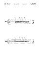
- FIG. 1 is a schematic representation of the apparatus with oxygen-reducing powder
- FIG. 2 is a schematic representation of the apparatus with rod-shaped oxygen-reducing means
- FIG. 3 is a schematic representation of the apparatus with wire-shaped oxygen-reducing means
- FIG. 4 is a schematic representation of the apparatus wherein the oxygen-reducing means has the shape of pellets or granules.
- FIG. 5 is a schematic representation of the apparatus with tube-shaped arrangement of the oxygen-reducing means.
- thermocouple which is arranged in the usual manner in a ceramic twin tube (not shown). This is surrounded by a closed-end aluminum oxide tube 1. The junction of the thermocouple is near the closed end of the aluminum oxide tube 1.
- the closed-end aluminum oxide tube 1 is placed in a protective casing 2 made of refractory metal oxide, such as aluminum oxide and graphite.
- This protective casing 2 has for the insertion of the closed-end aluminum oxide tube 1 a hollow cavity longitudinal to the protective casing 2, which opens at the end of the protective casing 2 opposite from the closed immersion end. Through this so-formed opening the aluminum oxide tube 1 with the thermocouple is inserted into the protective casing 2.
- the diameter of the hollow cavity is approximately 8-15 mm larger than the diameter of the aluminum oxide tube 1.
- the thus-created annulus 3 is filled with a mixture of aluminum oxide powder and aluminum powder, wherein the proportion of the aluminum powder at the time of filling is approximately 40% to 50% by volume.
- the apparatus shown in FIG. 2 is distinguished from that in FIG. 1 in that the reducing means is not in powder form but in the form of aluminum rods 4, which are arranged approximately parallel to the aluminum oxide tube 1, which encases the thermocouple. These aluminum rods 4 are embedded in the aluminum oxide powder. It is also possible to arrange the aluminum rods 4 in any other way, but the arrangement parallel to the aluminum oxide tube 1 is the most effective in respect to the reducing action.
- FIG. 3 A similar apparatus is displayed in FIG. 3.
- the distinguishing feature of this apparatus is that the reducing means is arranged in the form of wires 5 in the aluminum oxide powder.
- FIG. 4 Another possible form of the oxygen-reducing means is illustrated in FIG. 4.
- the reducing means is in the form of pellets or granules 6 of aluminum embedded in the aluminum oxide powder.
- the oxygen-reducing means is arranged as an aluminum tube 7 around the aluminum oxide powder.
- the aluminum tube 7 is only illustrated in cross-section. It can have cylinder walls which are closed or perforated in any desired manner. A tubular arrangement of metal powder is also possible.
- the oxygen-reducing aluminum melts.
- a downward running of the molten aluminum into the closed tip of the protective casing 2 is prevented in that the molten aluminum immediately enters into the hollow spaces made by the aluminum oxide powder and is thereby hindered from a downward movement.
Abstract
Description
Claims (13)
Applications Claiming Priority (2)
| Application Number | Priority Date | Filing Date | Title |
|---|---|---|---|
| DE4207317 | 1992-03-06 | ||
| DE4207317A DE4207317C3 (en) | 1992-03-06 | 1992-03-06 | Device for measuring the temperature of molten metal |
Publications (1)
| Publication Number | Publication Date |
|---|---|
| US5388908A true US5388908A (en) | 1995-02-14 |
Family
ID=6453518
Family Applications (1)
| Application Number | Title | Priority Date | Filing Date |
|---|---|---|---|
| US08/026,724 Expired - Lifetime US5388908A (en) | 1992-03-06 | 1993-03-05 | Apparatus for measuring the temperature of molten metals |
Country Status (9)
| Country | Link |
|---|---|
| US (1) | US5388908A (en) |
| EP (1) | EP0558808B1 (en) |
| JP (1) | JP3288791B2 (en) |
| AT (1) | ATE167292T1 (en) |
| AU (1) | AU655536B2 (en) |
| BR (1) | BR9300737A (en) |
| DE (2) | DE4207317C3 (en) |
| ES (1) | ES2119791T3 (en) |
| ZA (1) | ZA931576B (en) |
Cited By (13)
| Publication number | Priority date | Publication date | Assignee | Title |
|---|---|---|---|---|
| US5520461A (en) * | 1994-03-02 | 1996-05-28 | Alliedsignal Inc. | Airtight thermocouple probe |
| US6220748B1 (en) | 1999-01-15 | 2001-04-24 | Alcoa Inc. | Method and apparatus for testing material utilizing differential temperature measurements |
| US6280083B2 (en) * | 1998-01-12 | 2001-08-28 | Isuzu Ceramics Research Institute Co., Ltd. | Thermocouple lance with layered sheath for measuring temperature in molten metal |
| US6679627B1 (en) | 1997-11-04 | 2004-01-20 | Rdc Controle Ltee | Self-floating device for measuring the temperature of liquids |
| US20040047395A1 (en) * | 2000-07-12 | 2004-03-11 | Zhi Xie | Method for continuously measuring melting steel temperature and measuring temperature pipe |
| WO2005075949A1 (en) * | 2004-02-09 | 2005-08-18 | Temperaturmesstechnik Geraberg Gmbh | High-temperature sensor |
| US20060002449A1 (en) * | 2004-07-05 | 2006-01-05 | Heraeus Electro-Nite International N.V. | Container for molten metal, use of the container and method for determining an interface |
| US20070053405A1 (en) * | 2005-08-24 | 2007-03-08 | Heraeus Electro-Nite International N.V. | Device for measuring temperature in molten metals |
| US20100207306A1 (en) * | 2009-02-18 | 2010-08-19 | Heraeus Electro-Nite International N.V. | Temperature measuring device |
| WO2012055546A1 (en) | 2010-10-28 | 2012-05-03 | Heraeus Electro-Nite International N.V. | Wireless lance |
| CN103308192A (en) * | 2012-03-14 | 2013-09-18 | 贺利氏电子耐特国际股份公司 | Device for temperature measurement in metal melts |
| US9546909B2 (en) | 2013-02-08 | 2017-01-17 | Jyoti Goda | Apparatus and methods for continuous temperature measurement of molten metals |
| US10359589B2 (en) * | 2015-10-14 | 2019-07-23 | Heraeus Electro-Nite International N.V. | Cored wire, method and device for the production of the same |
Families Citing this family (3)
| Publication number | Priority date | Publication date | Assignee | Title |
|---|---|---|---|---|
| JP2000133986A (en) | 1998-10-27 | 2000-05-12 | Murata Mfg Co Ltd | Mounting structure of radiation noise suppressing part |
| JP4567131B2 (en) * | 1999-12-27 | 2010-10-20 | 川惣電機工業株式会社 | Continuous temperature measuring device |
| DE10236036B4 (en) * | 2002-08-06 | 2006-02-02 | Temperaturmeßtechnik Geraberg GmbH | High temperature sensor |
Citations (21)
| Publication number | Priority date | Publication date | Assignee | Title |
|---|---|---|---|---|
| DE834757C (en) * | 1950-11-26 | 1952-04-15 | Helmut V Zeppelin Dr | Device for measuring the temperature of molten metal and salt |
| US3232794A (en) * | 1963-06-04 | 1966-02-01 | Gen Electric | Thermocouple probe |
| GB1113460A (en) * | 1964-11-19 | 1968-05-15 | Corhart Refractories Co | Temperature-measuring apparatus |
| US3408607A (en) * | 1966-04-11 | 1968-10-29 | Continental Sensing Inc | Shielded conductor for use as thermoelectric transducer |
| DE1573271A1 (en) * | 1965-04-09 | 1970-06-04 | Plansee Metallwerk | Device for continuous thermoelectric measurement of the temperature of corrosive media |
| US3554816A (en) * | 1967-08-23 | 1971-01-12 | North American Rockwell | High temperature thermocouple containing conductors compositionally dissimilar |
| DE1648261A1 (en) * | 1965-04-09 | 1971-05-19 | Plansee Metallwerk | Device for continuous thermoelectric measurement of the temperature of corrosive media |
| US3649368A (en) * | 1968-12-18 | 1972-03-14 | Honeywell Inc | Measuring apparatus |
| DE7419633U (en) * | 1974-10-31 | Schuiling Metall Chemie Bv | Device for thermoelectric temperature measurement | |
| DE2427992A1 (en) * | 1973-06-13 | 1975-03-13 | Thermal Syndicate Ltd | METHOD OF MEASURING HIGH TEMPERATURES WITH THERMOCOUPLES |
| US3996071A (en) * | 1973-06-12 | 1976-12-07 | Friedrich Vade Gmbh | Temperature measuring device for use at pressures in excess of 1,500 bar |
| US4012708A (en) * | 1975-12-11 | 1977-03-15 | A. B. Chance Company | Oil immersible current limiting fuse assembly |
| US4060095A (en) * | 1975-08-23 | 1977-11-29 | Koransha Co., Ltd. | Thermocouple protecting tube |
| US4721534A (en) * | 1985-09-12 | 1988-01-26 | System Planning Corporation | Immersion pyrometer |
| GB2193375A (en) * | 1986-08-01 | 1988-02-03 | System Planning Corp | Protective structure for an immersion pyrometer |
| US4724428A (en) * | 1986-07-07 | 1988-02-09 | Emhart Industries, Inc. | Thermocouple jacket monitor |
| US4871263A (en) * | 1988-05-16 | 1989-10-03 | Pyromation, Inc. | Protective tube for a temperature sensor |
| US4977001A (en) * | 1986-08-01 | 1990-12-11 | Vesuvius Crucible Company | Protective cladding for a molybdenum substrate |
| US4984904A (en) * | 1987-12-24 | 1991-01-15 | Kawaso Electric Industrial Co., Ltd. | Apparatus for continuously measuring temperature of molten metal and method for making same |
| US5071258A (en) * | 1991-02-01 | 1991-12-10 | Vesuvius Crucible Company | Thermocouple assembly |
| US5209571A (en) * | 1992-07-09 | 1993-05-11 | Heraeus Electro-Nite International N.V. | Device for measuring the temperature of a molten metal |
Family Cites Families (1)
| Publication number | Priority date | Publication date | Assignee | Title |
|---|---|---|---|---|
| GB2079786B (en) * | 1980-07-01 | 1984-11-14 | Nat Res Dev | Production of viral antigens |
-
1992
- 1992-03-06 DE DE4207317A patent/DE4207317C3/en not_active Expired - Fee Related
- 1992-11-27 AT AT92120264T patent/ATE167292T1/en active
- 1992-11-27 ES ES92120264T patent/ES2119791T3/en not_active Expired - Lifetime
- 1992-11-27 DE DE59209372T patent/DE59209372D1/en not_active Expired - Lifetime
- 1992-11-27 EP EP92120264A patent/EP0558808B1/en not_active Expired - Lifetime
-
1993
- 1993-03-04 BR BR9300737A patent/BR9300737A/en not_active IP Right Cessation
- 1993-03-05 AU AU34032/93A patent/AU655536B2/en not_active Expired
- 1993-03-05 JP JP06916293A patent/JP3288791B2/en not_active Expired - Lifetime
- 1993-03-05 ZA ZA931576A patent/ZA931576B/en unknown
- 1993-03-05 US US08/026,724 patent/US5388908A/en not_active Expired - Lifetime
Patent Citations (21)
| Publication number | Priority date | Publication date | Assignee | Title |
|---|---|---|---|---|
| DE7419633U (en) * | 1974-10-31 | Schuiling Metall Chemie Bv | Device for thermoelectric temperature measurement | |
| DE834757C (en) * | 1950-11-26 | 1952-04-15 | Helmut V Zeppelin Dr | Device for measuring the temperature of molten metal and salt |
| US3232794A (en) * | 1963-06-04 | 1966-02-01 | Gen Electric | Thermocouple probe |
| GB1113460A (en) * | 1964-11-19 | 1968-05-15 | Corhart Refractories Co | Temperature-measuring apparatus |
| DE1573271A1 (en) * | 1965-04-09 | 1970-06-04 | Plansee Metallwerk | Device for continuous thermoelectric measurement of the temperature of corrosive media |
| DE1648261A1 (en) * | 1965-04-09 | 1971-05-19 | Plansee Metallwerk | Device for continuous thermoelectric measurement of the temperature of corrosive media |
| US3408607A (en) * | 1966-04-11 | 1968-10-29 | Continental Sensing Inc | Shielded conductor for use as thermoelectric transducer |
| US3554816A (en) * | 1967-08-23 | 1971-01-12 | North American Rockwell | High temperature thermocouple containing conductors compositionally dissimilar |
| US3649368A (en) * | 1968-12-18 | 1972-03-14 | Honeywell Inc | Measuring apparatus |
| US3996071A (en) * | 1973-06-12 | 1976-12-07 | Friedrich Vade Gmbh | Temperature measuring device for use at pressures in excess of 1,500 bar |
| DE2427992A1 (en) * | 1973-06-13 | 1975-03-13 | Thermal Syndicate Ltd | METHOD OF MEASURING HIGH TEMPERATURES WITH THERMOCOUPLES |
| US4060095A (en) * | 1975-08-23 | 1977-11-29 | Koransha Co., Ltd. | Thermocouple protecting tube |
| US4012708A (en) * | 1975-12-11 | 1977-03-15 | A. B. Chance Company | Oil immersible current limiting fuse assembly |
| US4721534A (en) * | 1985-09-12 | 1988-01-26 | System Planning Corporation | Immersion pyrometer |
| US4724428A (en) * | 1986-07-07 | 1988-02-09 | Emhart Industries, Inc. | Thermocouple jacket monitor |
| GB2193375A (en) * | 1986-08-01 | 1988-02-03 | System Planning Corp | Protective structure for an immersion pyrometer |
| US4977001A (en) * | 1986-08-01 | 1990-12-11 | Vesuvius Crucible Company | Protective cladding for a molybdenum substrate |
| US4984904A (en) * | 1987-12-24 | 1991-01-15 | Kawaso Electric Industrial Co., Ltd. | Apparatus for continuously measuring temperature of molten metal and method for making same |
| US4871263A (en) * | 1988-05-16 | 1989-10-03 | Pyromation, Inc. | Protective tube for a temperature sensor |
| US5071258A (en) * | 1991-02-01 | 1991-12-10 | Vesuvius Crucible Company | Thermocouple assembly |
| US5209571A (en) * | 1992-07-09 | 1993-05-11 | Heraeus Electro-Nite International N.V. | Device for measuring the temperature of a molten metal |
Non-Patent Citations (4)
| Title |
|---|
| Industrial Laboratory, V. N. Zhuchin E. A. "Protective Sheath For Thermocouples Measuring the Temperature", No. 4, Apr. 1984, pp. 385-387. |
| Industrial Laboratory, V. N. Zhuchin E. A. Protective Sheath For Thermocouples Measuring the Temperature , No. 4, Apr. 1984, pp. 385 387. * |
| Patent Abstracts of Japan, vol. 10, No. 237 (P 487)(2293) 15 Aug. 1986 & JP A 61 068525 (08 Apr. 1986)(only abstract considered). * |
| Patent Abstracts of Japan, vol. 10, No. 237 (P-487)(2293) 15 Aug. 1986 & JP-A-61 068525 (08 Apr. 1986)(only abstract considered). |
Cited By (31)
| Publication number | Priority date | Publication date | Assignee | Title |
|---|---|---|---|---|
| US5520461A (en) * | 1994-03-02 | 1996-05-28 | Alliedsignal Inc. | Airtight thermocouple probe |
| US6679627B1 (en) | 1997-11-04 | 2004-01-20 | Rdc Controle Ltee | Self-floating device for measuring the temperature of liquids |
| US6280083B2 (en) * | 1998-01-12 | 2001-08-28 | Isuzu Ceramics Research Institute Co., Ltd. | Thermocouple lance with layered sheath for measuring temperature in molten metal |
| US6220748B1 (en) | 1999-01-15 | 2001-04-24 | Alcoa Inc. | Method and apparatus for testing material utilizing differential temperature measurements |
| US20040047395A1 (en) * | 2000-07-12 | 2004-03-11 | Zhi Xie | Method for continuously measuring melting steel temperature and measuring temperature pipe |
| US6846105B2 (en) * | 2000-07-12 | 2005-01-25 | Northeastern University | Method for continuously measuring melting steel temperature and measuring temperature pipe |
| US20070171959A1 (en) * | 2004-02-09 | 2007-07-26 | Klaus Irrgang | High-temperature sensor |
| WO2005075949A1 (en) * | 2004-02-09 | 2005-08-18 | Temperaturmesstechnik Geraberg Gmbh | High-temperature sensor |
| US7740403B2 (en) | 2004-02-09 | 2010-06-22 | Temperaturmesstechnik Geraberg Gmbh | High-temperature sensor |
| EP1614489A1 (en) * | 2004-07-05 | 2006-01-11 | Heraeus Electro-Nite International N.V. | Molten metal vessel, its use and method for determining an interface |
| US20060002449A1 (en) * | 2004-07-05 | 2006-01-05 | Heraeus Electro-Nite International N.V. | Container for molten metal, use of the container and method for determining an interface |
| US9829385B2 (en) | 2004-07-05 | 2017-11-28 | Heraeus Electro-Nite International N.V. | Container for molten metal, use of the container and method for determining an interface |
| US20070053405A1 (en) * | 2005-08-24 | 2007-03-08 | Heraeus Electro-Nite International N.V. | Device for measuring temperature in molten metals |
| US20100046578A1 (en) * | 2005-08-24 | 2010-02-25 | Heraeus Electro-Nite International N.V. | Device for Measuring Temperature in Molten Metals |
| US7712957B2 (en) * | 2005-08-24 | 2010-05-11 | Heraeus Electro-Nite International N.V. | Device for measuring temperature in molten metals |
| US8033717B2 (en) | 2005-08-24 | 2011-10-11 | Heraeus Electro-Nite International N.V. | Device for measuring temperature in molten metals |
| US20100207306A1 (en) * | 2009-02-18 | 2010-08-19 | Heraeus Electro-Nite International N.V. | Temperature measuring device |
| CN102308191B (en) * | 2009-02-18 | 2014-06-18 | 贺利氏电子耐特国际股份公司 | Temperature measuring device |
| CN102308191A (en) * | 2009-02-18 | 2012-01-04 | 贺利氏电子耐特国际股份公司 | Temperature measuring device |
| US20110094920A1 (en) * | 2009-02-18 | 2011-04-28 | Heraeus Electro-Nite International N.V. | Container for molten metal |
| US8236234B2 (en) * | 2009-02-18 | 2012-08-07 | Heraeus Electro-Nite International N.V. | Container for molten metal |
| US8071012B2 (en) * | 2009-02-18 | 2011-12-06 | Heraeus Electro-Nite International N.V. | Temperature measuring device |
| US8864371B2 (en) | 2010-10-28 | 2014-10-21 | Heraeus Electro-Nite International N.V. | Wireless lance |
| WO2012055546A1 (en) | 2010-10-28 | 2012-05-03 | Heraeus Electro-Nite International N.V. | Wireless lance |
| US20130243031A1 (en) * | 2012-03-14 | 2013-09-19 | Heraeus Electro-Nite International N.V. | Device for measuring temperature in molten metal |
| CN103308192A (en) * | 2012-03-14 | 2013-09-18 | 贺利氏电子耐特国际股份公司 | Device for temperature measurement in metal melts |
| CN103308192B (en) * | 2012-03-14 | 2015-05-13 | 贺利氏电子耐特国际股份公司 | Device for temperature measurement in metal melts |
| US9182291B2 (en) * | 2012-03-14 | 2015-11-10 | Heraeus Electro-Nite International N.V. | Device for measuring temperature in molten metal |
| EP2639562A3 (en) * | 2012-03-14 | 2016-06-01 | Heraeus Electro-Nite International N.V. | Device for temperature measurement in metal melts |
| US9546909B2 (en) | 2013-02-08 | 2017-01-17 | Jyoti Goda | Apparatus and methods for continuous temperature measurement of molten metals |
| US10359589B2 (en) * | 2015-10-14 | 2019-07-23 | Heraeus Electro-Nite International N.V. | Cored wire, method and device for the production of the same |
Also Published As
| Publication number | Publication date |
|---|---|
| JPH0611396A (en) | 1994-01-21 |
| BR9300737A (en) | 1993-09-08 |
| DE4207317A1 (en) | 1993-09-09 |
| EP0558808A1 (en) | 1993-09-08 |
| ES2119791T3 (en) | 1998-10-16 |
| ATE167292T1 (en) | 1998-06-15 |
| ZA931576B (en) | 1993-09-27 |
| EP0558808B1 (en) | 1998-06-10 |
| DE4207317C2 (en) | 1995-09-07 |
| AU655536B2 (en) | 1994-12-22 |
| DE59209372D1 (en) | 1998-07-16 |
| AU3403293A (en) | 1993-09-09 |
| DE4207317C3 (en) | 2000-03-16 |
| JP3288791B2 (en) | 2002-06-04 |
Similar Documents
| Publication | Publication Date | Title |
|---|---|---|
| US5388908A (en) | Apparatus for measuring the temperature of molten metals | |
| US9182291B2 (en) | Device for measuring temperature in molten metal | |
| KR950006017B1 (en) | Thermocouple assembly | |
| US7712957B2 (en) | Device for measuring temperature in molten metals | |
| EP0454846A1 (en) | Thermocouple-type temperature sensor and method of measuring temperature of molten steel | |
| KR880003174A (en) | Temperature sensing device | |
| JP3816521B2 (en) | Drop-in immersion probe | |
| US4430518A (en) | Protecting tube for thermocouple | |
| US4977001A (en) | Protective cladding for a molybdenum substrate | |
| JPS61246636A (en) | Protective tube for continuously measuring temperature of molten steel | |
| US3652068A (en) | Refractory hollow body | |
| EP0014089B1 (en) | Exhaust gas sensor | |
| JP2613086B2 (en) | Thermocouple protection tube and its manufacturing method | |
| JP2002022554A (en) | Thermocouple for high temperature, and manufacturing method therefor | |
| JP2820423B2 (en) | Ceramic heater furnace | |
| JP2000088667A (en) | Fiber-reinforced thermocouple | |
| JP5228509B2 (en) | Probe for molten metal measurement | |
| JP3474015B2 (en) | Continuous measurement of oxygen activity in molten material | |
| GB2188431A (en) | Solid electrolyte oxygen probe | |
| JPH06298593A (en) | Apparatus for pulling up single crystal | |
| JP2003004539A (en) | Thermocouple for molten metal | |
| JPS62215862A (en) | Apparatus for measuring dissolved oxygen in molten steel | |
| JPH0373842A (en) | Probe for measuring activity of solute element in molten iron | |
| HU210031B (en) | Thermometer probe |
Legal Events
| Date | Code | Title | Description |
|---|---|---|---|
| AS | Assignment |
Owner name: HERAEUS ELECTRO-NITE INTERNATIONAL N.V., BELGIUM Free format text: ASSIGNMENT OF ASSIGNORS INTEREST;ASSIGNOR:KENDALL, MARTIN;REEL/FRAME:006537/0388 Effective date: 19930304 |
|
| STCF | Information on status: patent grant |
Free format text: PATENTED CASE |
|
| FPAY | Fee payment |
Year of fee payment: 4 |
|
| FEPP | Fee payment procedure |
Free format text: PAYER NUMBER DE-ASSIGNED (ORIGINAL EVENT CODE: RMPN); ENTITY STATUS OF PATENT OWNER: LARGE ENTITY Free format text: PAYOR NUMBER ASSIGNED (ORIGINAL EVENT CODE: ASPN); ENTITY STATUS OF PATENT OWNER: LARGE ENTITY |
|
| FPAY | Fee payment |
Year of fee payment: 8 |
|
| FPAY | Fee payment |
Year of fee payment: 12 |
|
| AS | Assignment |
Owner name: HERAEUS ELECTRO-NITE CO., PENNSYLVANIA Free format text: ASSIGNMENT OF ASSIGNORS INTEREST;ASSIGNOR:HERAEUS ELECTRO-NITE INTERNATIONAL N.V.;REEL/FRAME:021018/0812 Effective date: 20080529 |
|
| AS | Assignment |
Owner name: HERAEUS ELECTRO-NITE CO., LLC, PENNSYLVANIA Free format text: CHANGE OF NAME;ASSIGNOR:HERAEUS ELECTRO-NITE CO.;REEL/FRAME:023556/0910 Effective date: 20080701 |
|
| RR | Request for reexamination filed |
Effective date: 20091001 |
|
| B1 | Reexamination certificate first reexamination |
Free format text: THE PATENTABILITY OF CLAIMS 1-13 IS CONFIRMED. |