US5388564A - Compound bow - Google Patents
Compound bow Download PDFInfo
- Publication number
- US5388564A US5388564A US08/178,526 US17852694A US5388564A US 5388564 A US5388564 A US 5388564A US 17852694 A US17852694 A US 17852694A US 5388564 A US5388564 A US 5388564A
- Authority
- US
- United States
- Prior art keywords
- riser
- synchronizing
- cam pulley
- cam
- cable
- Prior art date
- Legal status (The legal status is an assumption and is not a legal conclusion. Google has not performed a legal analysis and makes no representation as to the accuracy of the status listed.)
- Expired - Fee Related
Links
- 150000001875 compounds Chemical class 0.000 title abstract description 13
- 230000011514 reflex Effects 0.000 claims abstract description 8
- 210000003414 extremity Anatomy 0.000 claims description 34
- 210000003141 lower extremity Anatomy 0.000 claims description 7
- 210000001364 upper extremity Anatomy 0.000 claims description 6
- 210000001015 abdomen Anatomy 0.000 description 3
- 239000002131 composite material Substances 0.000 description 1
- 238000010276 construction Methods 0.000 description 1
- 238000006073 displacement reaction Methods 0.000 description 1
- 238000012986 modification Methods 0.000 description 1
- 230000004048 modification Effects 0.000 description 1
- 230000002093 peripheral effect Effects 0.000 description 1
- 239000011435 rock Substances 0.000 description 1
- 238000004904 shortening Methods 0.000 description 1
Images

Classifications
-
- F—MECHANICAL ENGINEERING; LIGHTING; HEATING; WEAPONS; BLASTING
- F41—WEAPONS
- F41B—WEAPONS FOR PROJECTING MISSILES WITHOUT USE OF EXPLOSIVE OR COMBUSTIBLE PROPELLANT CHARGE; WEAPONS NOT OTHERWISE PROVIDED FOR
- F41B5/00—Bows; Crossbows
- F41B5/0094—Non-traditional bows, e.g. having hinged limbs or non-stave geometry
-
- F—MECHANICAL ENGINEERING; LIGHTING; HEATING; WEAPONS; BLASTING
- F41—WEAPONS
- F41B—WEAPONS FOR PROJECTING MISSILES WITHOUT USE OF EXPLOSIVE OR COMBUSTIBLE PROPELLANT CHARGE; WEAPONS NOT OTHERWISE PROVIDED FOR
- F41B5/00—Bows; Crossbows
- F41B5/10—Compound bows
-
- Y—GENERAL TAGGING OF NEW TECHNOLOGICAL DEVELOPMENTS; GENERAL TAGGING OF CROSS-SECTIONAL TECHNOLOGIES SPANNING OVER SEVERAL SECTIONS OF THE IPC; TECHNICAL SUBJECTS COVERED BY FORMER USPC CROSS-REFERENCE ART COLLECTIONS [XRACs] AND DIGESTS
- Y10—TECHNICAL SUBJECTS COVERED BY FORMER USPC
- Y10S—TECHNICAL SUBJECTS COVERED BY FORMER USPC CROSS-REFERENCE ART COLLECTIONS [XRACs] AND DIGESTS
- Y10S124/00—Mechanical guns and projectors
- Y10S124/90—Limb tip rotatable element structure
Definitions
- This invention relates to an improved compound bow of the type employing cams and control cables to achieve a programmed draw weight that varies in a selected fashion as a function of draw length.
- the invention is more particularly concerned with a compound bow in which the cam is interposed between an inboard spring limb member and an outboard rigid limb member.
- Pat. No. 4,287,867 describes a compound bow in which, on upper and lower ends of the riser, and outer rigid limb member is pivotally supported at its midsection on the outboard end of the cantilevered spring limb arm or power limb.
- a rotatable cam is pivotally supported on the riser, and a control cable which is received to the cam is connected at one end to the outer end of the spring limb arm and at the other end to the inboard end of the rigid limb member.
- the bowstring is strung between the outboard ends of the upper and lower rigid members.
- a synchronizing cable runs between upper and lower synchronizing wheels that turn with the rotatable cams.
- Drawing the bow string rotates the outer limb member and flexes the spring limb arm.
- the control cable rotates the cam, and the profile of the cam programs the draw weight as a function of draw length.
- the draw weight varies non-linearly over the draw length and drops off somewhat at full draw, with full draw weight being achieved a short distance ahead of full draw.
- the bow riser has spring power limbs cantilevered at its ends, respective cam pulleys pivotally mounted on outboard ends of the respective power limbs, and rigid limb members affixed to the cam pulleys.
- the bowstring extends between the ends of the two rigid limb members.
- a flexible, but inextensible cable runs from the end of the riser and passes over a peripheral cam groove of the cam pulley. An end of the cable is reeved in the cam pulley.
- a link member which can be a reflex cable in one embodiment, and can be a rigid rod in another embodiment, is coupled at one end to an outer point fixed with respect to the cam pulley and outer limb, and is coupled at its other end to the synchronizing pulley or wheel.
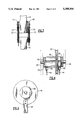
- FIG. 1 is a side elevation of a compound bow according to one embodiment of this invention.
- FIG. 2 shows an upper portion of this embodiment of the invention, in a drawn position.
- FIG. 3 is a top view of a cam pulley of this embodiment, taken at 3--3 of FIG. 2.
- FIG. 4 is a front view of a synchronizing pulley of this embodiment.
- FIG. 5 is a side view of the synchronizing pulley of this embodiment.
- FIG. 6 is a partial side elevation of a lower limb portion of a compound bow of an alternative embodiment.
- FIG. 1 shows a compound bow 10 of the present invention, which has a rigid elongated riser 12 or center portion.
- the bow 10 is considered in its conventional upright orientation, or shooting position.
- the riser 12 has a handle or grip portion 14 formed on it.
- a belly side of the riser faces the archer (on the right in this view) and a back side faces the target (on the left here).
- Attached at upper and lower ends of the riser are the link portions.
- a power limb 16 or spring lever is cantilevered.
- a rigid outer limb 18 is affixed to a respective cam pulley 20 that is pivoted on the free end of the associated power limb 16.
- each of the cam pulleys 20 is formed of a pair of cam plates 22, only one of which, per cam pulley, is shown in FIGS. 1 and 2, but both of which appear in FIG. 3.
- the cam pulley plates 22 are disposed on right and left sides of the bow 10, and have the same profiles.
- a bowstring 24 is attached to the outer ends of the two outer limbs 18.
- Synchronizing pulleys 26 are pivoted in upper and lower protuberances 28 at the ends of the riser 12.
- a continuous synchronizing cable 30, which is reeved to the synchronizing pulleys 26, passes over idler wheels 32 and through a vertical cable passage in the riser 12. The action of the synchronizing pulley and cable is well understood, and ensures even flexing of the upper and lower limbs.
- a cam cable 34 is provided for each of the upper and lower limbs, and rides in grooves 36 in the outer ends of the hub 38 of the synchronizing pulley 26.
- the cam cable extends outward and also rides in cam grooves 40 in the periphery of the respective cam plates 22, as shown in FIG. 3. Ends of the cam cable are reeved in the cam plates 22.
- a center part of the cable 34 passes through an axial passageway 42 in the hub 38 that connects the two end grooves 36.
- the cable 34 is not reeved to the synchronizing pulley 26. This construction ensures equal tension on the cable 34 on both the right and left sides, so that the flexing of the power limb 16 is fore-end-aft only, without twisting.
- a reflex cable 44 has one end affixed onto a fixed point 46 on the cam pulley 20, and has another end attached to a rigid bar 48 that projects radially from the synchronizing pulley 26 (see also FIG. 5).
- the bar 48 can be disposed centrally on the pulley 26, or there can be a pair of bars 48 on the ends of the pulley 26 so that the associated cable or cables 44 does not twist the outer limb 18.
- the one end of the reflex cable 44 could be affixed to a point on the rigid outer limb 18.
- the outer limb 18 and cam pulley 20 rotate to the position shown in FIG. 2.
- the cam pulley 20 winds the cable 34, and rotates the synchronizing wheel 26.
- the bar 48 pulls the reflex cable 44 downward, i.e., towards the riser 12, and this pulls the cam 20 downwards towards the riser, flexing the power limb 16.
- the power limb then supplies energy for the flight of the arrow, and pulls the rigid limb 18 back to the upright position when the bowstring 24 is released.
- the draw characteristic of the bow 10 is programmable by selecting cam plates 22 of suitable profile.
- cam inserts (not shown) can be placed on the cam plates 22 to alter the cam profile. This permits field programming of the bow, e.g. for reduced full draw weight, or to accommodate arrows of different weights or lengths.
- FIG. 6 A second embodiment of the bow of this invention will be described with reference to FIG. 6. Those elements of this embodiment that are shown in the FIG. 1 embodiment will be identified with the same reference numerals, and will not be described in detail again.
- a rigid linkage member or rod 50 is used in place of the reflex cable, and is pivoted on the fixed point 46 of the cam pulley 20.
- An inner end of the rod 60 is attached to a pivot 52 on the associated synchronizing pulley 26.
- a pair of cam cables 54 are employed at each end of the riser 12, although only the left side cable 54 of one pair is shown here.
- the cam cable 54 is affixed at one end to the end protuberance 28 of the riser 12, and rides on the associated cam plate 22, into which it is reeved.
- the synchronizing pulleys 26 function as described before.
- drawing the bowstring 24 rocks the outer limb 18 and the attached cam pulley 20, and the rigid rod 50 rotates the synchronizing pulley 26. Also, as the outer limb 18 rotates, the cables 54 ride in the grooves of the cam plates 22, shortening the distance to the riser 12, and thus imposing flexion on the associated power limb 16.
- the draw weight characteristic can be programmed by selecting a suitable profile of the cam plates 22.
- Alternative embodiments can be constructed with the cam pulleys 20 disposed to the belly side, rather than oriented towards the back side as shown here. Also, the rod or rigid linkage member 50 can be pivoted to the back side of the synchronizing pulley 26. The synchronizing pulleys 26 can alternatively be positioned behind the power limb 16, rather than the belly side, as shown.
- the power limb 16 is an elongated spring member, preferably formed of a composite material of good elasticity and a high spring constant.
Landscapes
- Engineering & Computer Science (AREA)
- General Engineering & Computer Science (AREA)
- Rehabilitation Tools (AREA)
Abstract
Description
Claims (8)
Priority Applications (1)
| Application Number | Priority Date | Filing Date | Title |
|---|---|---|---|
| US08/178,526 US5388564A (en) | 1994-01-05 | 1994-01-05 | Compound bow |
Applications Claiming Priority (1)
| Application Number | Priority Date | Filing Date | Title |
|---|---|---|---|
| US08/178,526 US5388564A (en) | 1994-01-05 | 1994-01-05 | Compound bow |
Publications (1)
| Publication Number | Publication Date |
|---|---|
| US5388564A true US5388564A (en) | 1995-02-14 |
Family
ID=22652885
Family Applications (1)
| Application Number | Title | Priority Date | Filing Date |
|---|---|---|---|
| US08/178,526 Expired - Fee Related US5388564A (en) | 1994-01-05 | 1994-01-05 | Compound bow |
Country Status (1)
| Country | Link |
|---|---|
| US (1) | US5388564A (en) |
Cited By (48)
| Publication number | Priority date | Publication date | Assignee | Title |
|---|---|---|---|---|
| US5499618A (en) * | 1994-09-20 | 1996-03-19 | Thompson; George E. | Lever action archery bow |
| US5535727A (en) * | 1994-12-07 | 1996-07-16 | Helmuth; Mark R. | Archery bow with plural cams and a timing wheel rotatable together about common axis |
| WO1997018430A1 (en) * | 1995-11-16 | 1997-05-22 | Peter Tchanev Balezov | Reflex cross-bow |
| US5638804A (en) * | 1996-03-11 | 1997-06-17 | Remick; Robert E. | Archery bow |
| US5651354A (en) * | 1996-07-12 | 1997-07-29 | La Haise, Sr.; Gerard A. | Twin limb bow |
| US5967132A (en) * | 1997-07-25 | 1999-10-19 | Lakewood Acquisitions | Compound bow |
| US5979425A (en) * | 1999-01-12 | 1999-11-09 | Loomis; L. Rodger | Adjustable compound bow |
| US6029644A (en) * | 1998-10-14 | 2000-02-29 | Bronnert; Herve X. | Bow limb articulation |
| US6067974A (en) * | 1998-03-05 | 2000-05-30 | Islas; John J. | Compound bow |
| US6076512A (en) * | 1998-11-10 | 2000-06-20 | Thielen; Joseph M. | Synchronized limb archery bow |
| US6306178B1 (en) | 1998-10-22 | 2001-10-23 | Fountainhead | Prosthetic device using a cam-shaped wheel |
| US6470870B1 (en) * | 2000-11-22 | 2002-10-29 | John G. Schaar | Synchronous compound bow with non-coplanar actuators and interchangeable leveraging components |
| US6776148B1 (en) | 2003-10-10 | 2004-08-17 | John J. Islas | Bowstring cam arrangement for compound bow |
| US7047958B1 (en) | 2003-09-03 | 2006-05-23 | Colley David E | Compact archery compound bow with improved efficiency features |
| US20070068514A1 (en) * | 2001-09-28 | 2007-03-29 | Kurve Technology, Inc. | Particle dispersion device for nasal delivery |
| US20070101980A1 (en) * | 2005-10-28 | 2007-05-10 | Steven Sims, Inc. | Compound bows |
| US20080251058A1 (en) * | 2007-04-13 | 2008-10-16 | Colley David E | Compact Crossbow with Improved Efficiency |
| US20090223500A1 (en) * | 2008-03-10 | 2009-09-10 | Stanziale Pasquale | Device for launching a projectile or a launch object in general |
| US20110041820A1 (en) * | 2008-03-10 | 2011-02-24 | Stanziale Pasquale | Device for launching a projectile or a launch object in general |
| US20110308508A1 (en) * | 2010-06-18 | 2011-12-22 | Islas John J | Bowstring Cam Arrangement for Compound Long Bow or Crossbow |
| US9234719B1 (en) * | 2014-09-25 | 2016-01-12 | James J. Kempf | Shooting bow with pulleys |
| US9255753B2 (en) | 2013-03-13 | 2016-02-09 | Ravin Crossbows, Llc | Energy storage device for a bow |
| US9255759B1 (en) * | 2015-05-07 | 2016-02-09 | Gene R. Archer | Compound bow draw weight adjuster operable at full draw and loft adjusting release and trolley arm |
| US9354015B2 (en) | 2013-12-16 | 2016-05-31 | Ravin Crossbows, Llc | String guide system for a bow |
| US9383159B2 (en) | 2013-03-13 | 2016-07-05 | Ravin Crossbows, Llc | De-cocking mechanism for a bow |
| US9494379B2 (en) | 2013-12-16 | 2016-11-15 | Ravin Crossbows, Llc | Crossbow |
| US9557134B1 (en) | 2015-10-22 | 2017-01-31 | Ravin Crossbows, Llc | Reduced friction trigger for a crossbow |
| US9879936B2 (en) | 2013-12-16 | 2018-01-30 | Ravin Crossbows, Llc | String guide for a bow |
| US10077963B1 (en) * | 2017-05-18 | 2018-09-18 | Sergey Popov | Double limb for arrow throwing device and arrow throwing device using the same |
| US10077965B2 (en) | 2013-12-16 | 2018-09-18 | Ravin Crossbows, Llc | Cocking system for a crossbow |
| US10082359B2 (en) | 2013-12-16 | 2018-09-25 | Ravin Crossbows, Llc | Torque control system for cocking a crossbow |
| US20180292165A1 (en) * | 2017-04-11 | 2018-10-11 | Danielsson Innovation Ab | Differential compound bow |
| US10126088B2 (en) | 2013-12-16 | 2018-11-13 | Ravin Crossbows, Llc | Crossbow |
| US10145642B1 (en) * | 2016-07-27 | 2018-12-04 | Rex F. Darlington | Archery bow |
| US10175023B2 (en) | 2013-12-16 | 2019-01-08 | Ravin Crossbows, Llc | Cocking system for a crossbow |
| US10209026B2 (en) | 2013-12-16 | 2019-02-19 | Ravin Crossbows, Llc | Crossbow with pulleys that rotate around stationary axes |
| US10254073B2 (en) | 2013-12-16 | 2019-04-09 | Ravin Crossbows, Llc | Crossbow |
| US10254075B2 (en) | 2013-12-16 | 2019-04-09 | Ravin Crossbows, Llc | Reduced length crossbow |
| US10921086B2 (en) | 2017-07-18 | 2021-02-16 | Krysse As | Line-based limb control system and method for archery bows |
| US10962322B2 (en) | 2013-12-16 | 2021-03-30 | Ravin Crossbows, Llc | Bow string cam arrangement for a compound bow |
| US11181336B2 (en) * | 2019-09-19 | 2021-11-23 | Krysse As | Archery bow operable to change tension |
| US11226167B2 (en) | 2019-01-15 | 2022-01-18 | Krysse As | Tension amplifying assembly and method for archery bows |
| US11320230B2 (en) | 2019-09-19 | 2022-05-03 | Krysse As | Archery device having a motion generator operable for different levels of tension |
| US12188740B2 (en) | 2013-12-16 | 2025-01-07 | Ravin Crossbows, Llc | Silent cocking system for a crossbow |
| US20250044053A1 (en) * | 2021-12-09 | 2025-02-06 | Rustam G. Mirzoev | Device for Synchronizing the Unwinding of Blocks of Tension Cables of Resilient Elements of a Compound Bow During Shooting |
| US20250093124A1 (en) * | 2023-09-20 | 2025-03-20 | Bear Archery, Inc. | Lever system for lever bow |
| US12449224B2 (en) | 2013-12-16 | 2025-10-21 | Ravin Crossbows, Llc | Arrow assembly for a crossbow and method of using same |
| US12566042B2 (en) | 2013-12-16 | 2026-03-03 | Ravin Crossbows, Llc | Reduced length crossbow |
Citations (8)
| Publication number | Priority date | Publication date | Assignee | Title |
|---|---|---|---|---|
| US3967609A (en) * | 1975-04-10 | 1976-07-06 | Frydenlund Arthur J | Compound bow |
| US3987777A (en) * | 1975-02-10 | 1976-10-26 | Darlington Rex F | Force multiplying type archery bow |
| US4077385A (en) * | 1976-07-26 | 1978-03-07 | Fredrickson Bert E | Compound bow stringing device and compound bow including the same |
| US4287867A (en) * | 1980-02-25 | 1981-09-08 | Victor United, Inc. | Compound bow |
| US4757799A (en) * | 1986-06-09 | 1988-07-19 | Bozek John W | Archery box with leveraged bending bowstring and separate launching bowstring |
| US4858588A (en) * | 1986-06-09 | 1989-08-22 | Bozek John W | Archery device with separate bending and lauching bowstrings and front end arrow launch |
| US5054463A (en) * | 1988-11-02 | 1991-10-08 | Colley David E | Power spring bow |
| US5353777A (en) * | 1992-12-28 | 1994-10-11 | Fincher Hollis W | Compound bow with diminishing draw weight and quick take down features |
-
1994
- 1994-01-05 US US08/178,526 patent/US5388564A/en not_active Expired - Fee Related
Patent Citations (8)
| Publication number | Priority date | Publication date | Assignee | Title |
|---|---|---|---|---|
| US3987777A (en) * | 1975-02-10 | 1976-10-26 | Darlington Rex F | Force multiplying type archery bow |
| US3967609A (en) * | 1975-04-10 | 1976-07-06 | Frydenlund Arthur J | Compound bow |
| US4077385A (en) * | 1976-07-26 | 1978-03-07 | Fredrickson Bert E | Compound bow stringing device and compound bow including the same |
| US4287867A (en) * | 1980-02-25 | 1981-09-08 | Victor United, Inc. | Compound bow |
| US4757799A (en) * | 1986-06-09 | 1988-07-19 | Bozek John W | Archery box with leveraged bending bowstring and separate launching bowstring |
| US4858588A (en) * | 1986-06-09 | 1989-08-22 | Bozek John W | Archery device with separate bending and lauching bowstrings and front end arrow launch |
| US5054463A (en) * | 1988-11-02 | 1991-10-08 | Colley David E | Power spring bow |
| US5353777A (en) * | 1992-12-28 | 1994-10-11 | Fincher Hollis W | Compound bow with diminishing draw weight and quick take down features |
Cited By (65)
| Publication number | Priority date | Publication date | Assignee | Title |
|---|---|---|---|---|
| US5499618A (en) * | 1994-09-20 | 1996-03-19 | Thompson; George E. | Lever action archery bow |
| US5535727A (en) * | 1994-12-07 | 1996-07-16 | Helmuth; Mark R. | Archery bow with plural cams and a timing wheel rotatable together about common axis |
| WO1997018430A1 (en) * | 1995-11-16 | 1997-05-22 | Peter Tchanev Balezov | Reflex cross-bow |
| US5638804A (en) * | 1996-03-11 | 1997-06-17 | Remick; Robert E. | Archery bow |
| US5651354A (en) * | 1996-07-12 | 1997-07-29 | La Haise, Sr.; Gerard A. | Twin limb bow |
| US5967132A (en) * | 1997-07-25 | 1999-10-19 | Lakewood Acquisitions | Compound bow |
| US6067974A (en) * | 1998-03-05 | 2000-05-30 | Islas; John J. | Compound bow |
| US6367464B1 (en) * | 1998-10-14 | 2002-04-09 | Herve X. Bronnert | Bow limb articulation |
| US6029644A (en) * | 1998-10-14 | 2000-02-29 | Bronnert; Herve X. | Bow limb articulation |
| US6306178B1 (en) | 1998-10-22 | 2001-10-23 | Fountainhead | Prosthetic device using a cam-shaped wheel |
| US6076512A (en) * | 1998-11-10 | 2000-06-20 | Thielen; Joseph M. | Synchronized limb archery bow |
| US5979425A (en) * | 1999-01-12 | 1999-11-09 | Loomis; L. Rodger | Adjustable compound bow |
| US6470870B1 (en) * | 2000-11-22 | 2002-10-29 | John G. Schaar | Synchronous compound bow with non-coplanar actuators and interchangeable leveraging components |
| US20070068514A1 (en) * | 2001-09-28 | 2007-03-29 | Kurve Technology, Inc. | Particle dispersion device for nasal delivery |
| US7047958B1 (en) | 2003-09-03 | 2006-05-23 | Colley David E | Compact archery compound bow with improved efficiency features |
| US6776148B1 (en) | 2003-10-10 | 2004-08-17 | John J. Islas | Bowstring cam arrangement for compound bow |
| US20070101980A1 (en) * | 2005-10-28 | 2007-05-10 | Steven Sims, Inc. | Compound bows |
| US20080251058A1 (en) * | 2007-04-13 | 2008-10-16 | Colley David E | Compact Crossbow with Improved Efficiency |
| US7891348B2 (en) | 2007-04-13 | 2011-02-22 | Colley David E | Compact crossbow with improved efficiency |
| US20090223500A1 (en) * | 2008-03-10 | 2009-09-10 | Stanziale Pasquale | Device for launching a projectile or a launch object in general |
| US20110041820A1 (en) * | 2008-03-10 | 2011-02-24 | Stanziale Pasquale | Device for launching a projectile or a launch object in general |
| US8899217B2 (en) * | 2010-06-18 | 2014-12-02 | Field Logic, Inc. | Bowstring cam arrangement for compound long bow or crossbow |
| US20140158105A1 (en) * | 2010-06-18 | 2014-06-12 | Field Logic, Inc | Bowstring cam arrangement for compound long bow or crossbow |
| US8651095B2 (en) * | 2010-06-18 | 2014-02-18 | John J. Islas | Bowstring cam arrangement for compound crossbow |
| US20110308508A1 (en) * | 2010-06-18 | 2011-12-22 | Islas John J | Bowstring Cam Arrangement for Compound Long Bow or Crossbow |
| US9383159B2 (en) | 2013-03-13 | 2016-07-05 | Ravin Crossbows, Llc | De-cocking mechanism for a bow |
| US10260835B2 (en) | 2013-03-13 | 2019-04-16 | Ravin Crossbows, Llc | Cocking mechanism for a crossbow |
| US12560404B2 (en) | 2013-03-13 | 2026-02-24 | Ravin Crossbows, Llc | Crossbow |
| US9255753B2 (en) | 2013-03-13 | 2016-02-09 | Ravin Crossbows, Llc | Energy storage device for a bow |
| US9879936B2 (en) | 2013-12-16 | 2018-01-30 | Ravin Crossbows, Llc | String guide for a bow |
| US10209026B2 (en) | 2013-12-16 | 2019-02-19 | Ravin Crossbows, Llc | Crossbow with pulleys that rotate around stationary axes |
| US9354015B2 (en) | 2013-12-16 | 2016-05-31 | Ravin Crossbows, Llc | String guide system for a bow |
| US11085728B2 (en) | 2013-12-16 | 2021-08-10 | Ravin Crossbows, Llc | Crossbow with cabling system |
| US12566042B2 (en) | 2013-12-16 | 2026-03-03 | Ravin Crossbows, Llc | Reduced length crossbow |
| US10962322B2 (en) | 2013-12-16 | 2021-03-30 | Ravin Crossbows, Llc | Bow string cam arrangement for a compound bow |
| US10254075B2 (en) | 2013-12-16 | 2019-04-09 | Ravin Crossbows, Llc | Reduced length crossbow |
| US10077965B2 (en) | 2013-12-16 | 2018-09-18 | Ravin Crossbows, Llc | Cocking system for a crossbow |
| US10082359B2 (en) | 2013-12-16 | 2018-09-25 | Ravin Crossbows, Llc | Torque control system for cocking a crossbow |
| US12449224B2 (en) | 2013-12-16 | 2025-10-21 | Ravin Crossbows, Llc | Arrow assembly for a crossbow and method of using same |
| US10126088B2 (en) | 2013-12-16 | 2018-11-13 | Ravin Crossbows, Llc | Crossbow |
| US12188740B2 (en) | 2013-12-16 | 2025-01-07 | Ravin Crossbows, Llc | Silent cocking system for a crossbow |
| US10175023B2 (en) | 2013-12-16 | 2019-01-08 | Ravin Crossbows, Llc | Cocking system for a crossbow |
| US9494379B2 (en) | 2013-12-16 | 2016-11-15 | Ravin Crossbows, Llc | Crossbow |
| US10254073B2 (en) | 2013-12-16 | 2019-04-09 | Ravin Crossbows, Llc | Crossbow |
| US11408705B2 (en) | 2013-12-16 | 2022-08-09 | Ravin Crossbows, Llc | Reduced length crossbow |
| US9234719B1 (en) * | 2014-09-25 | 2016-01-12 | James J. Kempf | Shooting bow with pulleys |
| US9255759B1 (en) * | 2015-05-07 | 2016-02-09 | Gene R. Archer | Compound bow draw weight adjuster operable at full draw and loft adjusting release and trolley arm |
| US9568271B2 (en) | 2015-05-07 | 2017-02-14 | Gene R. Archer | “Trolley” arm bow attachment for lofting an arrow above its line of sight to a target |
| US9557134B1 (en) | 2015-10-22 | 2017-01-31 | Ravin Crossbows, Llc | Reduced friction trigger for a crossbow |
| US9689638B1 (en) | 2015-10-22 | 2017-06-27 | Ravin Crossbows, Llc | Anti-dry fire system for a crossbow |
| US10145642B1 (en) * | 2016-07-27 | 2018-12-04 | Rex F. Darlington | Archery bow |
| US10254072B2 (en) * | 2017-04-11 | 2019-04-09 | Danielsson Innovation Ab | Differential compound bow |
| US20180292165A1 (en) * | 2017-04-11 | 2018-10-11 | Danielsson Innovation Ab | Differential compound bow |
| US10077963B1 (en) * | 2017-05-18 | 2018-09-18 | Sergey Popov | Double limb for arrow throwing device and arrow throwing device using the same |
| US11262152B2 (en) | 2017-07-18 | 2022-03-01 | Krysse As | Gear-based limb control system and method for archery bows |
| US11698240B2 (en) | 2017-07-18 | 2023-07-11 | Krysse As | Gear-based archery limb control system and method having a motion generator |
| US11029119B2 (en) | 2017-07-18 | 2021-06-08 | Krysse As | Archery system, bow and method operable with an energy resource |
| US10921086B2 (en) | 2017-07-18 | 2021-02-16 | Krysse As | Line-based limb control system and method for archery bows |
| US11802749B2 (en) | 2019-01-15 | 2023-10-31 | Krysse As | Motorized archery bow and method |
| US11226167B2 (en) | 2019-01-15 | 2022-01-18 | Krysse As | Tension amplifying assembly and method for archery bows |
| US11320230B2 (en) | 2019-09-19 | 2022-05-03 | Krysse As | Archery device having a motion generator operable for different levels of tension |
| US11181336B2 (en) * | 2019-09-19 | 2021-11-23 | Krysse As | Archery bow operable to change tension |
| US20250044053A1 (en) * | 2021-12-09 | 2025-02-06 | Rustam G. Mirzoev | Device for Synchronizing the Unwinding of Blocks of Tension Cables of Resilient Elements of a Compound Bow During Shooting |
| US20250093124A1 (en) * | 2023-09-20 | 2025-03-20 | Bear Archery, Inc. | Lever system for lever bow |
| US12590777B2 (en) * | 2023-09-20 | 2026-03-31 | Bear Archery, Inc. | Lever system for lever bow |
Similar Documents
| Publication | Publication Date | Title |
|---|---|---|
| US5388564A (en) | Compound bow | |
| US5211155A (en) | Eccentric pulley mechanism for compound archery bow | |
| US6776148B1 (en) | Bowstring cam arrangement for compound bow | |
| US3987777A (en) | Force multiplying type archery bow | |
| US4457288A (en) | Cam lever compound bow | |
| US6067974A (en) | Compound bow | |
| US4201182A (en) | Compound bow | |
| US20080135032A1 (en) | Bowstring Cam for Compound Bow | |
| US5054463A (en) | Power spring bow | |
| US4060066A (en) | Compound archery bow with eccentric cam elements | |
| CA2089799C (en) | Dual-feed single-cam compound bow | |
| US11112205B1 (en) | Projectile launching device with self-timing and without cam lean | |
| US4461267A (en) | Compound bow | |
| US4766874A (en) | Shooting crossbow | |
| US9459066B2 (en) | Compound bows with modified cams | |
| US4287867A (en) | Compound bow | |
| USRE39880E1 (en) | Dual-feed single-cam compound bow | |
| US8651095B2 (en) | Bowstring cam arrangement for compound crossbow | |
| US4722317A (en) | Archery bow | |
| US11525650B1 (en) | Firing system for a crossbow | |
| US6666202B1 (en) | Single-cam compound archery bow | |
| US20150184970A1 (en) | Double bow system | |
| US5638804A (en) | Archery bow | |
| US6371098B1 (en) | Split limb compact archery bow | |
| US20070101980A1 (en) | Compound bows |
Legal Events
| Date | Code | Title | Description |
|---|---|---|---|
| AS | Assignment |
Owner name: BOICE, RICHARD K., NEW YORK Free format text: ASSIGNMENT OF ASSIGNORS INTEREST;ASSIGNOR:ISLAS, JOHN J.;REEL/FRAME:008773/0321 Effective date: 19971025 |
|
| FEPP | Fee payment procedure |
Free format text: PAYOR NUMBER ASSIGNED (ORIGINAL EVENT CODE: ASPN); ENTITY STATUS OF PATENT OWNER: SMALL ENTITY |
|
| FEPP | Fee payment procedure |
Free format text: PAT HOLDER CLAIMS SMALL ENTITY STATUS - SMALL BUSINESS (ORIGINAL EVENT CODE: SM02); ENTITY STATUS OF PATENT OWNER: SMALL ENTITY |
|
| FPAY | Fee payment |
Year of fee payment: 4 |
|
| FPAY | Fee payment |
Year of fee payment: 8 |
|
| REMI | Maintenance fee reminder mailed | ||
| LAPS | Lapse for failure to pay maintenance fees | ||
| STCH | Information on status: patent discontinuation |
Free format text: PATENT EXPIRED DUE TO NONPAYMENT OF MAINTENANCE FEES UNDER 37 CFR 1.362 |
|
| FP | Lapsed due to failure to pay maintenance fee |
Effective date: 20070214 |