US5379965A - Plastic reel for material winding - Google Patents

Plastic reel for material winding Download PDF

Info

Publication number
US5379965A
US5379965A US08/013,946 US1394693A US5379965A US 5379965 A US5379965 A US 5379965A US 1394693 A US1394693 A US 1394693A US 5379965 A US5379965 A US 5379965A
Authority
US
United States
Prior art keywords
core
flange
reel
groove
spring
Prior art date
Legal status (The legal status is an assumption and is not a legal conclusion. Google has not performed a legal analysis and makes no representation as to the accuracy of the status listed.)
Expired - Fee Related
Application number
US08/013,946
Inventor
Herbert Isler
Karl-Gunter Schmidt
Current Assignee (The listed assignees may be inaccurate. Google has not performed a legal analysis and makes no representation or warranty as to the accuracy of the list.)
IWE-SPULENTECHNIK GmbH
Original Assignee
Swil Technik AG
Priority date (The priority date is an assumption and is not a legal conclusion. Google has not performed a legal analysis and makes no representation as to the accuracy of the date listed.)
Filing date
Publication date
Application filed by Swil Technik AG filed Critical Swil Technik AG
Assigned to SWIL-TECHNIK AG reassignment SWIL-TECHNIK AG ASSIGNMENT OF ASSIGNORS INTEREST. Assignors: ISLER, HERBERT, SCHMIDT, KARL-GUNTER
Application granted granted Critical
Publication of US5379965A publication Critical patent/US5379965A/en
Assigned to IWE-SPULENTECHNIK GMBH reassignment IWE-SPULENTECHNIK GMBH ASSIGNMENT OF ASSIGNORS INTEREST (SEE DOCUMENT FOR DETAILS). Assignors: SWIL-TECHNIK AG
Anticipated expiration legal-status Critical
Expired - Fee Related legal-status Critical Current

Links

Images

Classifications

    • FMECHANICAL ENGINEERING; LIGHTING; HEATING; WEAPONS; BLASTING
    • F16ENGINEERING ELEMENTS AND UNITS; GENERAL MEASURES FOR PRODUCING AND MAINTAINING EFFECTIVE FUNCTIONING OF MACHINES OR INSTALLATIONS; THERMAL INSULATION IN GENERAL
    • F16BDEVICES FOR FASTENING OR SECURING CONSTRUCTIONAL ELEMENTS OR MACHINE PARTS TOGETHER, e.g. NAILS, BOLTS, CIRCLIPS, CLAMPS, CLIPS OR WEDGES; JOINTS OR JOINTING
    • F16B21/00Means for preventing relative axial movement of a pin, spigot, shaft or the like and a member surrounding it; Stud-and-socket releasable fastenings
    • F16B21/10Means for preventing relative axial movement of a pin, spigot, shaft or the like and a member surrounding it; Stud-and-socket releasable fastenings by separate parts
    • F16B21/16Means for preventing relative axial movement of a pin, spigot, shaft or the like and a member surrounding it; Stud-and-socket releasable fastenings by separate parts with grooves or notches in the pin or shaft
    • BPERFORMING OPERATIONS; TRANSPORTING
    • B65CONVEYING; PACKING; STORING; HANDLING THIN OR FILAMENTARY MATERIAL
    • B65HHANDLING THIN OR FILAMENTARY MATERIAL, e.g. SHEETS, WEBS, CABLES
    • B65H75/00Storing webs, tapes, or filamentary material, e.g. on reels
    • B65H75/02Cores, formers, supports, or holders for coiled, wound, or folded material, e.g. reels, spindles, bobbins, cop tubes, cans, mandrels or chucks
    • B65H75/18Constructional details
    • B65H75/22Constructional details collapsible; with removable parts
    • B65H75/2245Constructional details collapsible; with removable parts connecting flange to hub
    • BPERFORMING OPERATIONS; TRANSPORTING
    • B65CONVEYING; PACKING; STORING; HANDLING THIN OR FILAMENTARY MATERIAL
    • B65HHANDLING THIN OR FILAMENTARY MATERIAL, e.g. SHEETS, WEBS, CABLES
    • B65H75/00Storing webs, tapes, or filamentary material, e.g. on reels
    • B65H75/02Cores, formers, supports, or holders for coiled, wound, or folded material, e.g. reels, spindles, bobbins, cop tubes, cans, mandrels or chucks
    • B65H75/18Constructional details
    • B65H75/22Constructional details collapsible; with removable parts
    • B65H75/2254Constructional details collapsible; with removable parts with particular joining means for releasably connecting parts
    • B65H75/2263Discrete fasteners, e.g. bolts or screws
    • BPERFORMING OPERATIONS; TRANSPORTING
    • B65CONVEYING; PACKING; STORING; HANDLING THIN OR FILAMENTARY MATERIAL
    • B65HHANDLING THIN OR FILAMENTARY MATERIAL, e.g. SHEETS, WEBS, CABLES
    • B65H2701/00Handled material; Storage means
    • B65H2701/50Storage means for webs, tapes, or filamentary material
    • B65H2701/51Cores or reels characterised by the material
    • B65H2701/512Cores or reels characterised by the material moulded
    • B65H2701/5122Plastics

Definitions

  • This invention relates to a plastic reel for winding material and more particularly, to an improved reel for winding cable.
  • a plastic reel consisting of a two-part core and two flanges is known from the DE-PS 37 12 680.
  • the halves of the core positively engage, in the axial direction, the circumferential grooves of a hub that is integrally attached to the flanges. In the circumferential direction, the engagement is non-positive.
  • the flanges are clamped against the core halves by tie rods which pass all the way through.
  • the DE-OS 2 245 595 proposes that plastic reels be produced from cast polyamide by in situ polymerization.
  • the core is inserted, with a tubular attachment, into an annular groove of the flange, so that it interlocks positively in the radial direction.
  • the flanges are likewise clamped against one another by means of tie rods.
  • core halves of a plastic reel can be connected positively to the flanges in the circumferential direction.
  • sprung bolts shaped like a truncated cone, which latch into conical recesses in the core halves.
  • Another plastic reel consisting of a hollow cylindrical core and two flanges, is known from the DE-OS 28 22 213.
  • the core is designed in two parts and positively engages the flanges in the axial direction.
  • Cotter pins are used to make a positive connection in the radial and circumferential direction. They are inserted into the flanges, gripped behind an axially protruding ring of the core halves, and act as dogs with respect to the radial ribs of the core. However, only moderate torques can be transmitted with this type of connection.
  • a reel made of plastic for winding material such as cables is formed from a cylindrical core and two flanges positively engaged at both ends of the core.
  • the hollow cylindrical core is formed of at least two core parts whose outside surfaces when joined form a circular cylindrical shape.
  • the two flanges disposed on each of the two face ends of the core positively engage the respective ends of the core in the radial and circumferential directions.
  • At least four removable connection elements per flange connect the flange with the core in the axial direction.
  • Another object of the invention is to provide an improved plastic reel having improved engagement between the core and flanges.
  • FIG. 1 shows a representation of a reel in perspective
  • FIG. 2 shows a frontal view of a core half
  • FIG. 3 shows a frontal view in the direction of the arrow III in FIG. 2, on a reduced scale
  • FIG. 4 shows a frontal view of a part of the flange
  • FIG. 5 shows an outside view of the flange
  • FIG. 6 shows a view of a clamping device
  • FIG. 7 shows a section along the line VII--VII in FIG. 6;
  • FIG. 8 shows a section through the connection between the flange and the core
  • FIG. 9 shows a section along the line IX--IX in FIG. 8.
  • FIG. 10 shows a cut-out of an axial section through a worm
  • FIG. 11 shows a second embodiment of a core
  • FIG. 12 shows a view of a variant of the flange.
  • the reel 1 of FIG. 1 consists of a core 2, two identical flanges 3, and optionally also of a worm 4 inserted between one of the flanges 3 and the core 2.
  • the core 2 is divided into two core halves 6 along a plane which contains the reel axis 5.
  • the core halves 6, the flanges 3 and the worm 4 are cast of a high-strength plastic, preferably of a nylon block copolymer, for example "NYRIM" (Registered Trademark). NYRIM is mixed in liquid form from three components and is then cast in a mold at approximately atmospheric pressure. The mold has vent holes. Polymerization is subsequently initiated by an admixed catalyst. The polymerization creates an over-pressure of only about 0.3 bar.
  • NYRIM is very tough, has good abrasion properties, and good chemical and heat stability, is fully recyclable, such that a granulate of NYRIM is a high-grade material for injection molding. When the utilized material is reused, primary quality is achieved at the secondary stage.
  • FIGS. 2 and 3 show one of the two identical core halves 6. It has a cylindrical wall 10. Two axis-parallel longitudinal ribs 11 and also, depending on the length of the core 2, two or more reinforcement ribs 13 extending in the circumferential direction are integrally attached to the inside of the cylindrical wall. Three beads 12 are integrally attached to each of the two face ends. The beads 12 have axis-parallel, cylindrical holes 14. The holes 14 are open towards the face surfaces 16.
  • the wall 10 is reinforced on both sides against the separation plane 17 which contains the axis 5. At the contact surface 18, which lies in the separation plane 17, an axis-parallel spring 20, which passes all the way through, is physically attached to one side of the bead 19.
  • the other bead 19 has an axis parallel groove 21 of the same width.
  • FIG. 4 shows a portion of the inside of the flange 3.
  • the flange 3 has the circumferential groove 30 with an outer flank 31, in the shape of a circular cylinder, and with an unround inner flank 32, which is matched to the inside contour of the assembled core 2.
  • the front end of the core 2 is inserted into this groove 30, and is then connected positively to the flange 3 in the circumferential and radial directions. In this way, large forces and torques can be transmitted between the flange 3 and the core 2.
  • the reel thus can also be constructed with a larger diameter, for which previous plastic reels could not be used.
  • the front ends of the core 2 and the groove 30 can be designed slightly wedge-shaped in their axial section.
  • the flange 3 Radially outside the groove 30, the flange 3 has a smooth, flat inside wall 33, which is reinforced on the outside by radial ribs 34 and by a cylindrical rib 35 (FIG. 5). An axial, cylindrical ring 36, protruding towards the outside, is integrally attached to the wall 33 along its periphery. Inside the groove 30, the flange 3 is reinforced by section-like recesses 37 and elevations 38 to a hub 39 with a through-hole 40. Two of these elevations 38, which are situated opposite one another, extend over a larger angular region and are used to affix a written text, for example to identify the cable type and the reel manufacturer. These wider elevations 38 are reinforced by further radial ribs 41.
  • the through-holes 45 with cylindrical countersinks 46 from the outside are provided in the widened parts 44 of the groove 30. These widened parts 44 are used to receive the beads 12.
  • the through-holes 45 are flush with the holes 14 of the inserted core 2.
  • Two longitudinal holes 47 are used to insert a dog to drive or brake the reel on a mandrel which is placed through the hubs 39.
  • An opening 48 is provided in the wall 33 outside the groove 30.
  • the cable lead optionally can be brought out there.
  • several pairs of holes 49 to fasten the cable end are distributed over the circumference.
  • the flange 3 On its outside, the flange 3 has three protrusions 50 in the shape of a circular arc, and three recesses 51 in the shape of a circular arc.
  • the protrusions 50 are wedge-shaped on both sides to reduce the risk of injury when the reel is rotated.
  • the recesses 51 are less deep than the protrusions 50 are high. In this way, the two flanges that contact one another have a certain gripping distance from one another.
  • FIGS. 6 and 7 show a clamping device 52 for clamping a cable lead 53 which is brought out from the opening 48.
  • the clamping lever 55 is pivotably mounted on an axle 54.
  • the lever 55 On its periphery, the lever 55 has a spiral-shaped groove 57, which is open toward the wall 33 and toward a cylindrical surface 56, this groove 57 having small ribs 58.
  • the groove 57 becomes narrower towards the outside.
  • the lever 55 is loaded by a spring 59 in the counter-clockwise direction.
  • the surface 56 and the wall 33 also have small ribs 60 in the region of the lever 55.
  • the clamping device 52 actually can also be used sensibly with other reels or in other applications to clamp fast strand-shaped materials, for example ropes, pipes, or profiles.
  • FIGS. 8 and 9 show the axial fastening of the flange 3 and the core 2.
  • a metal insert 65 with a through-hole 66 is screwed into the holes 14. Adjoining the inside end, two slits 67 with a radial, flat shoulder 68 are milled into the insert 65.
  • a spring clip 69 made of spring steel wire with a rectangular cross-section, is snapped into the slits 67. The two arms of the clip 69 contact the shoulder 68.
  • the clip 69 cal also be secured by a sleeve 72.
  • the sleeve 72 can also be closed at the face end.
  • the insert 65 is also suited for integral casting.
  • the shaft 73 of a pin 74 is put through the hole 45 of the flange 3.
  • the pin 74 has a head 75 with axis-parallel holes 76 for inserting a special key.
  • the face surface 77 of the head 74 is approximately flush with the face surface 78 of the flange 3.
  • a washer 80 lies on the base 79 of the recess 46. It is held on the shaft 73 by means of a snap ring, so that it cannot loosen.
  • a pressure spring 82 is tensioned between the head 75 and the washer 80.
  • the inside end of the shaft 73 is shown below the axis 71 in the assembled state, turned by 90° above the axis 71.
  • the shaft 73 has two opposite wedge-shaped surfaces 86, which constrict towards the face end 87 and two transverse grooves 88 at a distance from the face end 87.
  • the shoulder 89 of these grooves 88 which is closer to the face end 87, is slightly undercut, so that the arms 70 latch securely in the grooves 88.
  • the pin 75 is pushed through the holes 45, 66, until the wedge-shaped surfaces 86 contact the arm 70.
  • the pin 74 is thus positioned correctly automatically. Now the head 75 is struck with a hammer, so that the spring clip 69 is set, and the spring 82 is tensioned.
  • the arms 70 latch in the grooves 88.
  • the holes 76 of the head 75 are engaged by a special key, the pin 74 is turned by 90°, so that the arms 70 are spread again and the pin 74 is pressed out through the force of the spring 82.
  • connection described above makes is possible to perform the assembly extremely quickly by means of untrained personnel and nevertheless to specify the axial connection force within close limits. This force also remains constant over a longer period of time despite possible creepage of the material.
  • connection can easily be automated, by pressing in the pins 74, for example, by means of a stamp.
  • connection described above naturally can also be used with the same advantages to connect components other than the core and the flange of a reel.
  • FIG. 10 shows a portion of an axial section through the assembled worm 4.
  • the worm 4 has a flat wall 92 which faces the interior space of the reel 1.
  • the wall 92 is reinforced on its back side by ribs, which are not shown.
  • On its inside, the wall 92 goes over into a tubular attachment 93.
  • the attachment 93 has a groove 94, which has a design identical to that of the groove 30 of the flange 3, and into which groove the core 2 is inserted.
  • the attachment 93 has a shape that is identical .to that of the face end of the core 2. This face end of the attachment 93 is inserted into the groove 30.
  • the attachment has axis-parallel through-holes.
  • a channel 95 extends tangentially from the inside diameter and goes over arc-shaped tangentially into the outside circumference.
  • the worm 4 is suitably omitted.
  • the reel can be disposed of as a pure type in case it is damaged, which considerably facilitates reuse.
  • FIG. 11 shows a variant of the core 2, in which this core consists of three core thirds.
  • the same reference symbols are used for analogous parts, so that a detailed description of these parts is obviated.
  • the inside radius of the radial ribs 13 is here the same as the outside radius of the wall 10.
  • the casting mold for the design according to FIG. 11 can be produced cheaply.
  • the disassembled core of FIG. 11 can be stored in a smaller space than the core 2 of FIGS. 2 and 3.
  • the flange 3 according to FIG. 12 is suited for the three-part core 2 of FIG. 11.
  • too analogous parts bear the same reference symbols.

Abstract

The reel comprises a two-part core 2 with a shape of a hollow cylinder, with a flange 3 at each of its two ends. The flange 3 and the core 2 are positively engaged in the circumferential and radial direction, and are connected to one another by at least four detachable connection elements per flange 3. By means of this design, large forces and torques can be transferred between the flange 3 and the core 2 so that larger reel diameters of plastic can also be constructed.

Description

BACKGROUND OF THE INVENTION
This invention relates to a plastic reel for winding material and more particularly, to an improved reel for winding cable.
A plastic reel consisting of a two-part core and two flanges is known from the DE-PS 37 12 680. The halves of the core positively engage, in the axial direction, the circumferential grooves of a hub that is integrally attached to the flanges. In the circumferential direction, the engagement is non-positive. The flanges are clamped against the core halves by tie rods which pass all the way through.
The DE-OS 2 245 595 proposes that plastic reels be produced from cast polyamide by in situ polymerization. Here the core is inserted, with a tubular attachment, into an annular groove of the flange, so that it interlocks positively in the radial direction. The flanges are likewise clamped against one another by means of tie rods.
From the FR-PS 1 219 868, it is further known, that core halves of a plastic reel can be connected positively to the flanges in the circumferential direction. For the connection in the radial direction, one uses sprung bolts, shaped like a truncated cone, which latch into conical recesses in the core halves.
Another plastic reel, consisting of a hollow cylindrical core and two flanges, is known from the DE-OS 28 22 213. The core is designed in two parts and positively engages the flanges in the axial direction. Cotter pins are used to make a positive connection in the radial and circumferential direction. They are inserted into the flanges, gripped behind an axially protruding ring of the core halves, and act as dogs with respect to the radial ribs of the core. However, only moderate torques can be transmitted with this type of connection.
All these reels have in common that, at least in one are not suited for larger reel diameters and consequently for wound material of considerable weight.
It is an object of the present invention to design a plastic reel in such a fashion that it is also suited for larger reel diameters. This object is achieved by the combination of characteristics according to the claims.
SUMMARY OF THE INVENTION
A reel made of plastic for winding material such as cables is formed from a cylindrical core and two flanges positively engaged at both ends of the core. The hollow cylindrical core is formed of at least two core parts whose outside surfaces when joined form a circular cylindrical shape. The two flanges disposed on each of the two face ends of the core positively engage the respective ends of the core in the radial and circumferential directions. At least four removable connection elements per flange connect the flange with the core in the axial direction.
Accordingly, it is an object of the invention to provide an improved plastic reel.
Another object of the invention is to provide an improved plastic reel having improved engagement between the core and flanges.
Still other objects and advantages of the invention will in part be obvious and will in part be apparent from the specification.
The invention accordingly comprises the features of construction, combination of elements, and arrangement of parts which will be exemplified in the construction hereinafter set forth, and the scope of the invention will be indicated in the claims.
BRIEF DESCRIPTION OF THE DRAWINGS
For a fuller understanding of the invention, reference is had to the following description taken in connection with the accompanying drawings, in which:
FIG. 1 shows a representation of a reel in perspective;
FIG. 2 shows a frontal view of a core half;
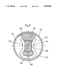
FIG. 3 shows a frontal view in the direction of the arrow III in FIG. 2, on a reduced scale;
FIG. 4 shows a frontal view of a part of the flange;
FIG. 5 shows an outside view of the flange;
FIG. 6 shows a view of a clamping device;
FIG. 7 shows a section along the line VII--VII in FIG. 6;
FIG. 8 shows a section through the connection between the flange and the core;
FIG. 9 shows a section along the line IX--IX in FIG. 8;
FIG. 10 shows a cut-out of an axial section through a worm;
FIG. 11 shows a second embodiment of a core; and
FIG. 12 shows a view of a variant of the flange.
DESCRIPTION OF THE PREFERRED EMBODIMENT
The reel 1 of FIG. 1 consists of a core 2, two identical flanges 3, and optionally also of a worm 4 inserted between one of the flanges 3 and the core 2. The core 2 is divided into two core halves 6 along a plane which contains the reel axis 5. The core halves 6, the flanges 3 and the worm 4 are cast of a high-strength plastic, preferably of a nylon block copolymer, for example "NYRIM" (Registered Trademark). NYRIM is mixed in liquid form from three components and is then cast in a mold at approximately atmospheric pressure. The mold has vent holes. Polymerization is subsequently initiated by an admixed catalyst. The polymerization creates an over-pressure of only about 0.3 bar. In contrast to an injection molding process, which requires high pressures, large-area parts can be produced on simple tool holders by means of this casting process. NYRIM is very tough, has good abrasion properties, and good chemical and heat stability, is fully recyclable, such that a granulate of NYRIM is a high-grade material for injection molding. When the utilized material is reused, primary quality is achieved at the secondary stage.
FIGS. 2 and 3 show one of the two identical core halves 6. It has a cylindrical wall 10. Two axis-parallel longitudinal ribs 11 and also, depending on the length of the core 2, two or more reinforcement ribs 13 extending in the circumferential direction are integrally attached to the inside of the cylindrical wall. Three beads 12 are integrally attached to each of the two face ends. The beads 12 have axis-parallel, cylindrical holes 14. The holes 14 are open towards the face surfaces 16. The wall 10 is reinforced on both sides against the separation plane 17 which contains the axis 5. At the contact surface 18, which lies in the separation plane 17, an axis-parallel spring 20, which passes all the way through, is physically attached to one side of the bead 19. The other bead 19 has an axis parallel groove 21 of the same width.
FIG. 4 shows a portion of the inside of the flange 3. The flange 3 has the circumferential groove 30 with an outer flank 31, in the shape of a circular cylinder, and with an unround inner flank 32, which is matched to the inside contour of the assembled core 2. The front end of the core 2 is inserted into this groove 30, and is then connected positively to the flange 3 in the circumferential and radial directions. In this way, large forces and torques can be transmitted between the flange 3 and the core 2. The reel thus can also be constructed with a larger diameter, for which previous plastic reels could not be used. To achieve an engagement between the core 2 and the flange 3, which is free of backlash, the front ends of the core 2 and the groove 30 can be designed slightly wedge-shaped in their axial section.
Radially outside the groove 30, the flange 3 has a smooth, flat inside wall 33, which is reinforced on the outside by radial ribs 34 and by a cylindrical rib 35 (FIG. 5). An axial, cylindrical ring 36, protruding towards the outside, is integrally attached to the wall 33 along its periphery. Inside the groove 30, the flange 3 is reinforced by section-like recesses 37 and elevations 38 to a hub 39 with a through-hole 40. Two of these elevations 38, which are situated opposite one another, extend over a larger angular region and are used to affix a written text, for example to identify the cable type and the reel manufacturer. These wider elevations 38 are reinforced by further radial ribs 41.
Six through-holes 45 with cylindrical countersinks 46 from the outside are provided in the widened parts 44 of the groove 30. These widened parts 44 are used to receive the beads 12. The through-holes 45 are flush with the holes 14 of the inserted core 2. Two longitudinal holes 47 are used to insert a dog to drive or brake the reel on a mandrel which is placed through the hubs 39. An opening 48 is provided in the wall 33 outside the groove 30. The cable lead optionally can be brought out there. Furthermore, along the periphery, several pairs of holes 49 to fasten the cable end are distributed over the circumference. On its outside, the flange 3 has three protrusions 50 in the shape of a circular arc, and three recesses 51 in the shape of a circular arc. These are used for the positive engagement of reels that are stacked on one another. The protrusions 50 are wedge-shaped on both sides to reduce the risk of injury when the reel is rotated. The recesses 51 are less deep than the protrusions 50 are high. In this way, the two flanges that contact one another have a certain gripping distance from one another.
FIGS. 6 and 7 show a clamping device 52 for clamping a cable lead 53 which is brought out from the opening 48. The clamping lever 55 is pivotably mounted on an axle 54. On its periphery, the lever 55 has a spiral-shaped groove 57, which is open toward the wall 33 and toward a cylindrical surface 56, this groove 57 having small ribs 58. The groove 57 becomes narrower towards the outside. In the representation of FIG. 6, the lever 55 is loaded by a spring 59 in the counter-clockwise direction. The surface 56 and the wall 33 also have small ribs 60 in the region of the lever 55. To clamp the cable lead 53 fast, the lever 55 is first swung manually clockwise, and the cable lead 53 is conducted under the lever 55. When the lever 55 is released, it is pressed by the spring 59 against the cable lead 53. When there is tension on the cable, the cable is wedged because of the spiral-shaped groove 57, and is held securely. The groove, which constricts against the cable end, makes it possible to clamp different cable diameters without any problem.
The clamping device 52 actually can also be used sensibly with other reels or in other applications to clamp fast strand-shaped materials, for example ropes, pipes, or profiles.
FIGS. 8 and 9 show the axial fastening of the flange 3 and the core 2. A metal insert 65 with a through-hole 66 is screwed into the holes 14. Adjoining the inside end, two slits 67 with a radial, flat shoulder 68 are milled into the insert 65. A spring clip 69, made of spring steel wire with a rectangular cross-section, is snapped into the slits 67. The two arms of the clip 69 contact the shoulder 68. The clip 69 cal also be secured by a sleeve 72. The sleeve 72 can also be closed at the face end. In this case, the insert 65 is also suited for integral casting. The shaft 73 of a pin 74 is put through the hole 45 of the flange 3. At its outer end, the pin 74 has a head 75 with axis-parallel holes 76 for inserting a special key. In the assembled state, the face surface 77 of the head 74 is approximately flush with the face surface 78 of the flange 3. A washer 80 lies on the base 79 of the recess 46. It is held on the shaft 73 by means of a snap ring, so that it cannot loosen. A pressure spring 82 is tensioned between the head 75 and the washer 80.
The inside end of the shaft 73 is shown below the axis 71 in the assembled state, turned by 90° above the axis 71. The shaft 73 has two opposite wedge-shaped surfaces 86, which constrict towards the face end 87 and two transverse grooves 88 at a distance from the face end 87. The shoulder 89 of these grooves 88, which is closer to the face end 87, is slightly undercut, so that the arms 70 latch securely in the grooves 88. For assembly, the pin 75 is pushed through the holes 45, 66, until the wedge-shaped surfaces 86 contact the arm 70. The pin 74 is thus positioned correctly automatically. Now the head 75 is struck with a hammer, so that the spring clip 69 is set, and the spring 82 is tensioned. The arms 70 latch in the grooves 88. For disassembly, the holes 76 of the head 75 are engaged by a special key, the pin 74 is turned by 90°, so that the arms 70 are spread again and the pin 74 is pressed out through the force of the spring 82.
The connection described above makes is possible to perform the assembly extremely quickly by means of untrained personnel and nevertheless to specify the axial connection force within close limits. This force also remains constant over a longer period of time despite possible creepage of the material.
By contrast, for example the screw connection with dynamometric keys requires more time as well as trained personnel, and does not by any means achieve the constancy and precision of the connecting force as does the connection described here.
The connection can easily be automated, by pressing in the pins 74, for example, by means of a stamp. The connection described above naturally can also be used with the same advantages to connect components other than the core and the flange of a reel.
FIG. 10 shows a portion of an axial section through the assembled worm 4. The worm 4 has a flat wall 92 which faces the interior space of the reel 1. The wall 92 is reinforced on its back side by ribs, which are not shown. On its inside, the wall 92 goes over into a tubular attachment 93. The attachment 93 has a groove 94, which has a design identical to that of the groove 30 of the flange 3, and into which groove the core 2 is inserted. At its other face, the attachment 93 has a shape that is identical .to that of the face end of the core 2. This face end of the attachment 93 is inserted into the groove 30. At the location of the bead 12, the attachment has axis-parallel through-holes. A channel 95 extends tangentially from the inside diameter and goes over arc-shaped tangentially into the outside circumference.
If the worm is to be inserted, appropriately longer pins 74 are used. The type of connection of the worm 4, which has been described above, has the advantage that the interior space of the reel 1 is the same with and without the worm 4, with the same core length. Assembly of the worm requires hardly any additional effort.
If the cable lead is to be conducted through the opening 48, the worm 4 is suitably omitted.
Since the few metal parts of the reel 1 are all easily disassembled, the reel can be disposed of as a pure type in case it is damaged, which considerably facilitates reuse.
FIG. 11 shows a variant of the core 2, in which this core consists of three core thirds. The same reference symbols are used for analogous parts, so that a detailed description of these parts is obviated. The inside radius of the radial ribs 13 is here the same as the outside radius of the wall 10. Thus, the core segments 6 can readily be stacked. The casting mold for the design according to FIG. 11 can be produced cheaply. The disassembled core of FIG. 11 can be stored in a smaller space than the core 2 of FIGS. 2 and 3.
The flange 3 according to FIG. 12 is suited for the three-part core 2 of FIG. 11. Here, too analogous parts bear the same reference symbols.
It will thus be seen that the objects set forth above, among those made apparent from the preceding description, are efficiently attained and, since certain changes may be made in the above construction without departing from the spirit and scope of the invention, it is intended that all matter contained in the above description or shown in the accompanying drawings shall be interpreted as illustrative and not in a limiting sense.
It is also to be understood that the following claims are intended to cover all of the generic and specific features of the invention herein described and all statements of the scope of the invention which, as a matter of language, might be said to fall therebetween.

Claims (9)

What is claimed is:
1. A reel made of plastic for winding material such as cables, comprising:
a hollow cylindrical core (2), formed of at least two core parts (6), the outside surfaces having circular cylindrical shapes,
a flange (3) disposed on each of the two face ends of the core (2), each flange directly engaging the respective ends of the core (2) in the radial and circumferential directions, each flange being formed with a groove (30) open to one face end of core (2), said groove (30) having a substantially circular cylindrical outer flank (31) and an unround inner flank (32) adapted to the inside contour of said core (2) and wherein at least a first face side of the core (2) is inserted into the groove (30), and
at least two removable connection elements (74) for each core part (6) on both sides thereof directly connecting the flange (3) with the core (2) in the axial direction.
2. The reel of claim 1, further including a worm (4) of plastic with a channel (95) for bringing out the inside end of the wound material, the worm being fastened on the inside of one of the flanges (3), wherein the worm (4) has another circumferential groove (94) on one face side, said groove having a design that is identical to that of the groove (30) of the flange (3) and wherein the second face side of the core (2) is inserted into this further circumferential groove (94).
3. The reel of claim 1, wherein the core parts (6) include form locking engagement means for directly engaging another core part in the radial direction along contact surfaces (18).
4. The reel of claim 3, wherein the form locking engagement means at each contact surface (18) of the core parts (6) includes a groove (21) in one of the core parts running in the axial direction, and an integrally attached spring (20) on the adjoining core part is engaged within the groove (21).
5. A reel made of plastic for winding material such as cables, comprising:
a hollow cylindrical core (2), formed of at least two core parts (6), the outside surfaces having circular cylindrical shapes,
a flange (3) disposed on each of the two face ends of the core (2), each flange directly engaging the respective ends of the core (2) in the radial and circumferential directions, and
at least two removable connection elements for each flange (3), for connecting the flange (3) with the core (2) in the axial direction,
each connection element includes an axis-parallel pin (74) having a head (75) and a shaft (73), and the head (75) has key insertion elements (76) for turning the pin (74), and the shaft (73) has to wedge-shaped surfaces (86) at that end which is situated opposite to the head, and also has two diametrically opposite transverse grooves (88) which run perpendicular to the pin axis (71), a spring (82) is inserted between the head (75) and a washer (80), the core (2) is formed with a hole (14) at each connection point for receiving the connection element, and an insert (65) is inserted into each hole 14 at each connection point, and two spring elements (70) disposed in the insert at a distance from one another, which engage the transverse grooves (88) when the pin is inserted.
6. The reel of claim 5, wherein the washer (80) is retained on the shaft (73) so that it cannot loosen.
7. The reel of claim 5, wherein the spring elements are formed of two arms (70) of a clip (69) that is made of spring steel wire with a rectangular cross-section, and wherein the clip (69) is snapped into milled grooves (67) of the insert (65).
8. The reel of claim 6, wherein the spring elements are formed of two arms (70) of a clip (69) that is made of spring steel wire with a rectangular cross-section, and wherein the clip (69) is snapped into milled grooves (67) of the insert (65).
9. A reel made of plastic for winding material such as cables, comprising:
a hollow cylindrical core (2), formed of at least two core parts (6), the outside surfaces having circular cylindrical shapes,
a flange (3) disposed on each of the two face ends of the core (2), each flange directly engaging the respective ends of the core (2) in the radial and circumferential directions, at least one of the flanges (3) being formed with a cable lead-through opening (48) adjoining the outside circumference of the core (2), and a spring-loaded clamping element (52) is pivotably mounted at the flange next to the opening (48), said clamping element (52) having a spiral-shaped groove (57) for clamping a cable lead (53) that is conducted through the opening (48), and
at least two removable connection elements for each core part (6) on both sides thereof directly connecting the flange (3) with the core (2) in the axial direction.
US08/013,946 1992-02-05 1993-02-04 Plastic reel for material winding Expired - Fee Related US5379965A (en)

Applications Claiming Priority (2)

Application Number Priority Date Filing Date Title
CH336/92 1992-02-05
CH336/92A CH684592A5 (en) 1992-02-05 1992-02-05 Plastic reel on a winding.

Publications (1)

Publication Number Publication Date
US5379965A true US5379965A (en) 1995-01-10

Family

ID=4184698

Family Applications (1)

Application Number Title Priority Date Filing Date
US08/013,946 Expired - Fee Related US5379965A (en) 1992-02-05 1993-02-04 Plastic reel for material winding

Country Status (4)

Country Link
US (1) US5379965A (en)
EP (1) EP0556154A1 (en)
JP (1) JPH05254736A (en)
CH (1) CH684592A5 (en)

Cited By (19)

* Cited by examiner, † Cited by third party
Publication number Priority date Publication date Assignee Title
US5743486A (en) * 1996-12-12 1998-04-28 Reel-Core, Inc. Knockdown reel
US5868348A (en) * 1998-02-11 1999-02-09 Reel-Core, Inc. Reel assembly
US5967454A (en) * 1998-11-30 1999-10-19 Formall, Inc. Twin sheet reel core
US6491246B1 (en) * 1999-12-13 2002-12-10 Eastman Kodak Company Pinch spools one-time use cameras apparatus and methods
US6622365B2 (en) 1999-12-13 2003-09-23 Eastman Kodak Company Pinch quill, apparatus, and film winding method
US6883744B2 (en) 2001-11-19 2005-04-26 Sonoco Development, Inc. Spool for optical fiber media
US20050139723A1 (en) * 2003-12-08 2005-06-30 Couchey Brian P. Spool having reversing spiral guide
CN100418869C (en) * 2006-04-21 2008-09-17 刘忠 Large industrial axle
US20080307691A1 (en) * 2004-07-26 2008-12-18 Halldor Egill Guonason High Speed, Increased Hydrodynamic Efficiency, Light-Weight Molded Trawl Door and Methods for Use and Manufacture
US20090095834A1 (en) * 2007-10-11 2009-04-16 Lincoln Global, Inc. Spool for retaining wire
US20090314877A1 (en) * 1998-02-13 2009-12-24 Ripplinger C Robert Corrugated flanges for spools and reels
US9617112B1 (en) 2009-10-23 2017-04-11 Southwire Company, Llc Independently rotatable flanges and attachable arbor hole adapters
USD808937S1 (en) * 2016-12-30 2018-01-30 Liangyi Zheng Microphone
USD836560S1 (en) 2016-06-23 2018-12-25 Southwire Company, Llc Flange with vertical slot and jack
CN109552940A (en) * 2018-11-16 2019-04-02 合肥智瑞工程科技有限公司 For cable winding, bundled traction device
US10766735B2 (en) 2015-08-19 2020-09-08 Southwire Company, Llc Flange stand and adapter for flanges
USD898676S1 (en) 2016-06-23 2020-10-13 Southwire Company, Llc Flange
USD899379S1 (en) 2016-06-23 2020-10-20 Southwire Company, Llc Flange
US11697569B2 (en) 2021-03-02 2023-07-11 Sonoco Development, Inc. Sliding lock for break-down spool

Families Citing this family (6)

* Cited by examiner, † Cited by third party
Publication number Priority date Publication date Assignee Title
DE29520038U1 (en) * 1995-12-18 1996-02-15 Koch Jakob Reusable spool, divided into two, flangeless, thin-walled with stiffening webs for winding ropes, tapes and the like. made of nature and plastic materials
US5897075A (en) * 1997-05-30 1999-04-27 Vandor Corporation Reel assembly
JP4047589B2 (en) * 2002-01-23 2008-02-13 岐阜プラスチック工業株式会社 Cable winding drum
FR2898351B1 (en) * 2006-03-13 2009-07-17 Efsa S A METAL WINDING COIL FOR CABLE, TUBE OR SIMILAR
CN107720418A (en) * 2017-09-28 2018-02-23 江阴市永昌交通机械部件有限公司 It is a kind of to be easy to fixed control wire wrap-up
JP6899361B2 (en) * 2018-08-31 2021-07-07 株式会社フジクラ・ダイヤケーブル drum

Citations (13)

* Cited by examiner, † Cited by third party
Publication number Priority date Publication date Assignee Title
US1408261A (en) * 1920-09-25 1922-02-28 Charles B Brookhart Holder for clotheslines and the like
US1625503A (en) * 1925-10-08 1927-04-19 Standard Underground Cable Co Canada Cable reel
US2193407A (en) * 1939-11-08 1940-03-12 Harry J Hagen Rope clamp
US2442398A (en) * 1945-01-18 1948-06-01 Edward F Chandler Fastening device
US2499268A (en) * 1949-05-10 1950-02-28 Lestershire Spool And Mfg Comp Unit bobbin construction
US2846162A (en) * 1955-09-12 1958-08-05 Int Harvester Co Cable drum
FR1219868A (en) * 1958-12-17 1960-05-20 Michelin Italiana Spool for winding metal wires and braids, in particular for their use in the manufacture of tires for motor vehicles
DE1916306A1 (en) * 1969-03-29 1970-10-08 Hoechst Ag Collapsible cable drum made of thermoplastic material
DE2245595A1 (en) * 1972-09-16 1974-03-21 Hans Loeckmann Collapsible plastics cable drum - has a core and L/H and R/H side discs, which permit improved storage of empty drums
DE2822213A1 (en) * 1978-05-22 1979-11-29 Theysohn Friedrich Fa Dismantlable cable drum construction - has cylindrical core and two end flanges connected releasably to core and having grooves
GB2074642A (en) * 1980-04-25 1981-11-04 Houplain D A Fastener device
US4471919A (en) * 1982-09-13 1984-09-18 Crellin, Inc. Utility reel
US4976475A (en) * 1988-05-19 1990-12-11 Ab Varnamo Gummifabrik Knock down spool

Family Cites Families (3)

* Cited by examiner, † Cited by third party
Publication number Priority date Publication date Assignee Title
DE3712680C1 (en) * 1987-04-14 1988-10-20 Stewing Kunststoffbetr Gmbh Cable drum which can be dismantled
US4938432A (en) * 1989-04-12 1990-07-03 Cooper Industries, Inc. Cable spool with integral end storage flange
DE9107854U1 (en) * 1991-06-26 1991-09-12 Stewing Kunststoffbetrieb Gmbh, 4270 Dorsten, De

Patent Citations (13)

* Cited by examiner, † Cited by third party
Publication number Priority date Publication date Assignee Title
US1408261A (en) * 1920-09-25 1922-02-28 Charles B Brookhart Holder for clotheslines and the like
US1625503A (en) * 1925-10-08 1927-04-19 Standard Underground Cable Co Canada Cable reel
US2193407A (en) * 1939-11-08 1940-03-12 Harry J Hagen Rope clamp
US2442398A (en) * 1945-01-18 1948-06-01 Edward F Chandler Fastening device
US2499268A (en) * 1949-05-10 1950-02-28 Lestershire Spool And Mfg Comp Unit bobbin construction
US2846162A (en) * 1955-09-12 1958-08-05 Int Harvester Co Cable drum
FR1219868A (en) * 1958-12-17 1960-05-20 Michelin Italiana Spool for winding metal wires and braids, in particular for their use in the manufacture of tires for motor vehicles
DE1916306A1 (en) * 1969-03-29 1970-10-08 Hoechst Ag Collapsible cable drum made of thermoplastic material
DE2245595A1 (en) * 1972-09-16 1974-03-21 Hans Loeckmann Collapsible plastics cable drum - has a core and L/H and R/H side discs, which permit improved storage of empty drums
DE2822213A1 (en) * 1978-05-22 1979-11-29 Theysohn Friedrich Fa Dismantlable cable drum construction - has cylindrical core and two end flanges connected releasably to core and having grooves
GB2074642A (en) * 1980-04-25 1981-11-04 Houplain D A Fastener device
US4471919A (en) * 1982-09-13 1984-09-18 Crellin, Inc. Utility reel
US4976475A (en) * 1988-05-19 1990-12-11 Ab Varnamo Gummifabrik Knock down spool

Cited By (27)

* Cited by examiner, † Cited by third party
Publication number Priority date Publication date Assignee Title
US5743486A (en) * 1996-12-12 1998-04-28 Reel-Core, Inc. Knockdown reel
US5868348A (en) * 1998-02-11 1999-02-09 Reel-Core, Inc. Reel assembly
US20090314877A1 (en) * 1998-02-13 2009-12-24 Ripplinger C Robert Corrugated flanges for spools and reels
US8567037B2 (en) 1998-02-13 2013-10-29 Sonoco Development, Inc. Method of forming a reel having corrugated flanges
US8286906B2 (en) * 1998-02-13 2012-10-16 Sonoco Development, Inc. Corrugated flanges for spools and reels
US5967454A (en) * 1998-11-30 1999-10-19 Formall, Inc. Twin sheet reel core
US6491246B1 (en) * 1999-12-13 2002-12-10 Eastman Kodak Company Pinch spools one-time use cameras apparatus and methods
US6622365B2 (en) 1999-12-13 2003-09-23 Eastman Kodak Company Pinch quill, apparatus, and film winding method
US20030190165A1 (en) * 1999-12-13 2003-10-09 North Stephen P. Pinch quill, apparatus, and film winding method
US6883744B2 (en) 2001-11-19 2005-04-26 Sonoco Development, Inc. Spool for optical fiber media
US7237746B2 (en) 2003-12-08 2007-07-03 Sonoco Development, Inc. Spool having reversing spiral guide
US20050139723A1 (en) * 2003-12-08 2005-06-30 Couchey Brian P. Spool having reversing spiral guide
US20080307691A1 (en) * 2004-07-26 2008-12-18 Halldor Egill Guonason High Speed, Increased Hydrodynamic Efficiency, Light-Weight Molded Trawl Door and Methods for Use and Manufacture
CN100418869C (en) * 2006-04-21 2008-09-17 刘忠 Large industrial axle
US20090095834A1 (en) * 2007-10-11 2009-04-16 Lincoln Global, Inc. Spool for retaining wire
US7954748B2 (en) * 2007-10-11 2011-06-07 Lincoln Global, Inc. Spool for retaining wire
US10221036B2 (en) 2009-10-23 2019-03-05 Southwire Company, Llc Independently rotatable flanges and attachable arbor hole adapters
US9617112B1 (en) 2009-10-23 2017-04-11 Southwire Company, Llc Independently rotatable flanges and attachable arbor hole adapters
US10766735B2 (en) 2015-08-19 2020-09-08 Southwire Company, Llc Flange stand and adapter for flanges
US9828209B2 (en) 2015-08-19 2017-11-28 Southwire Company, Llc Independently rotatable flanges and attachable arbor hole adapters
US11124382B2 (en) 2015-08-19 2021-09-21 Southwire Company, Llc Independently rotatable flanges and attachable arbor hole adapters
USD836560S1 (en) 2016-06-23 2018-12-25 Southwire Company, Llc Flange with vertical slot and jack
USD898676S1 (en) 2016-06-23 2020-10-13 Southwire Company, Llc Flange
USD899379S1 (en) 2016-06-23 2020-10-20 Southwire Company, Llc Flange
USD808937S1 (en) * 2016-12-30 2018-01-30 Liangyi Zheng Microphone
CN109552940A (en) * 2018-11-16 2019-04-02 合肥智瑞工程科技有限公司 For cable winding, bundled traction device
US11697569B2 (en) 2021-03-02 2023-07-11 Sonoco Development, Inc. Sliding lock for break-down spool

Also Published As

Publication number Publication date
CH684592A5 (en) 1994-10-31
EP0556154A1 (en) 1993-08-18
JPH05254736A (en) 1993-10-05

Similar Documents

Publication Publication Date Title
US5379965A (en) Plastic reel for material winding
US4720075A (en) Shock isolating mount
AU691683B2 (en) Nut for a fastener assembly
CA2004099C (en) Spring element for a shock isolating mount
US4118020A (en) Spring assembly and method of assembly thereof
US4783039A (en) Shock isolating mount
US5352055A (en) Locking member and stabilizer bar/locking member combination
CA2158521C (en) Quick connect tube couplings
USRE41296E1 (en) Retainer ring for securely retaining a first object to a second object
US7108248B2 (en) Cable pulley block having detachable fastening of a cable to a cable drum
US6065737A (en) Tensioning device
WO2012018782A2 (en) Hose clamp with parallel tightening and rapid release
US4494889A (en) Shaft bushing and hub assembly
US6095481A (en) Breakaway shock isolating mount
US5116176A (en) Expansion anchor
US20210039432A1 (en) Emergency wheel
US3913954A (en) Pipe locking device
US4062574A (en) Fitting assembly
US4269371A (en) Composite, heavy-duty spool with plastic end cones
US5127641A (en) Air spring having a sleeve-like flexible member
US6345783B1 (en) Spool rack with connecting system
EP0492921A2 (en) A pipe coupling
KR960003516B1 (en) Quick release collar
US4674549A (en) Bead lock device
US4343564A (en) Rotatable member rigidly mounted on an undersize shaft

Legal Events

Date Code Title Description
AS Assignment

Owner name: SWIL-TECHNIK AG, SWITZERLAND

Free format text: ASSIGNMENT OF ASSIGNORS INTEREST.;ASSIGNORS:ISLER, HERBERT;SCHMIDT, KARL-GUNTER;REEL/FRAME:006518/0295

Effective date: 19930405

AS Assignment

Owner name: IWE-SPULENTECHNIK GMBH, GERMANY

Free format text: ASSIGNMENT OF ASSIGNORS INTEREST;ASSIGNOR:SWIL-TECHNIK AG;REEL/FRAME:007317/0394

Effective date: 19941229

LAPS Lapse for failure to pay maintenance fees
FP Lapsed due to failure to pay maintenance fee

Effective date: 19990110

STCH Information on status: patent discontinuation

Free format text: PATENT EXPIRED DUE TO NONPAYMENT OF MAINTENANCE FEES UNDER 37 CFR 1.362