US5375446A - Rotary expanded grid cutter and related process - Google Patents
Rotary expanded grid cutter and related process Download PDFInfo
- Publication number
- US5375446A US5375446A US08/143,785 US14378593A US5375446A US 5375446 A US5375446 A US 5375446A US 14378593 A US14378593 A US 14378593A US 5375446 A US5375446 A US 5375446A
- Authority
- US
- United States
- Prior art keywords
- strip
- tooth
- disk
- shaft
- angle
- Prior art date
- Legal status (The legal status is an assumption and is not a legal conclusion. Google has not performed a legal analysis and makes no representation as to the accuracy of the status listed.)
- Expired - Fee Related
Links
- 238000000034 method Methods 0.000 title claims abstract description 24
- 230000008569 process Effects 0.000 title description 8
- 239000002184 metal Substances 0.000 claims abstract description 12
- 230000006872 improvement Effects 0.000 claims abstract description 6
- 125000006850 spacer group Chemical group 0.000 claims description 9
- 230000003993 interaction Effects 0.000 description 3
- 230000002093 peripheral effect Effects 0.000 description 3
- 230000035515 penetration Effects 0.000 description 2
- 238000010348 incorporation Methods 0.000 description 1
- 238000012986 modification Methods 0.000 description 1
- 230000004048 modification Effects 0.000 description 1
- 239000000843 powder Substances 0.000 description 1
Images


Classifications
-
- B—PERFORMING OPERATIONS; TRANSPORTING
- B21—MECHANICAL METAL-WORKING WITHOUT ESSENTIALLY REMOVING MATERIAL; PUNCHING METAL
- B21D—WORKING OR PROCESSING OF SHEET METAL OR METAL TUBES, RODS OR PROFILES WITHOUT ESSENTIALLY REMOVING MATERIAL; PUNCHING METAL
- B21D31/00—Other methods for working sheet metal, metal tubes, metal profiles
- B21D31/04—Expanding other than provided for in groups B21D1/00 - B21D28/00, e.g. for making expanded metal
- B21D31/046—Expanding other than provided for in groups B21D1/00 - B21D28/00, e.g. for making expanded metal making use of rotating cutters
-
- Y—GENERAL TAGGING OF NEW TECHNOLOGICAL DEVELOPMENTS; GENERAL TAGGING OF CROSS-SECTIONAL TECHNOLOGIES SPANNING OVER SEVERAL SECTIONS OF THE IPC; TECHNICAL SUBJECTS COVERED BY FORMER USPC CROSS-REFERENCE ART COLLECTIONS [XRACs] AND DIGESTS
- Y10—TECHNICAL SUBJECTS COVERED BY FORMER USPC
- Y10T—TECHNICAL SUBJECTS COVERED BY FORMER US CLASSIFICATION
- Y10T29/00—Metal working
- Y10T29/18—Expanded metal making
Definitions
- This invention relates to improvements to conventional rotary expanded battery grid processes and, specifically, to a cutter tool configuration which produces a sufficiently thin mesh to allow pasting to a required weight.
- Electrodes of battery cells often comprise an expanded metal sheet, the openings and surfaces of which carry a chemically active powder.
- a method and apparatus for producing an expanded grid is disclosed in U.S. Pat. No. 3,760,470.
- U.S. Pat. No. 4,291,443 discloses a conventional three roll cluster (where the strip passes between first and second rolls in a preforming/slitting stage, and then between the second and a third roll in a final slitting stage) for preforming and slitting a sheet to produce an expanded metal mesh, the entirety of which is incorporated herein by reference.
- U.S. Pat. No. 4,297,866 discloses an improved process for producing expanded metal sheet by concurrently slitting and preforming the strip.
- the length of one side of a triangle corresponding to the tooth configuration, and collinear with the leading tooth surface is less than the length of another side of the triangle corresponding to and collinear with the trailing tooth surface.
- the entry angle formed between the side of the triangle corresponding to the leading surface and the base of the triangle is less than 90°.
- the convexly shaped tooth surfaces used to deform slit segments out of the plane of the sheet or strip are asymmetrically shaped. Problems have been experienced with asymmetrical cutters, however.
- a two or three roll cluster is utilized, with the geometry of the cutter teeth for the roll pair which performs the strip based on calculations when the tool exits the strip.
- the focus is on the interaction of the first and second rolls, i.e., during the preforming/slitting stage, while the interaction between the second and third rolls in the final slitting stage forms no part of this invention.
- the trailing edge angle of the tooth is always less than 45°, and is determined as a function of the radius of the tooth root, the depth of the tooth and the thickness of the strip.
- the entry angle is then made equal to the trailing angle, and therefore it follows that the nose angle (the angle between the leading and trailing surfaces, at the apex of the tooth) is always greater than 90°.
- T strip thickness
- T strip thickness.
- the above described tool and related method produce a uniformly thin, expanded metal product for use as a battery grid that may be accurately pasted to the required weight.
- FIG. 1 is a side elevation of a conventional three roll cluster used to preform and then slit a metal sheet;
- FIG. 3 is a schematic plan view of a conventional upper disk of the type used in the roll cluster shown in FIG. 1;
- FIG. 4 is a side elevation of an upper preforming disk in accordance with this invention.
- FIG. 5 is an enlarged detail taken from the disk of FIG. 4;
- FIG. 6 is a side elevation of an upper preforming/slitting disk of the type employed as the lower roll in the three roll cluster of FIG. 1 but wherein the teeth of the disk are formed in accordance with this invention.
- a strip 10 enters the cluster of three rolls 12, 14 and 16, each roll having a plurality of spaced disks 18, 20, 22, respectively.
- the disks of each roll are separated by spacers 24, and possibly other spacers such as that shown at 26, depending on the configuration of the sheet, as best seen in FIG. 3.
- the first and second sets of disks 18 and 20 have toothed peripheral edges, laterally aligned by keying the disks 18 and 20 to the respective shafts 28, 30.
- These first and second sets of disks 18 and 20 have teeth 32 with identical tooth profiles.
- the lower roll disks 20 have cutting edges 21 between each pair of teeth 32, but the tooth profiles themselves are identical to those of the roll disks 18.
- the disk/spacer arrangement on upper and lower disk rolls 12 and 14 involves a lateral offset so that the disks 18 intermesh with the disks 20, i.e., the disks 18 of the upper roll 12 fit within the spaces between the disks 20 of the lower roll 14.
- These preforming disk rolls 12 and 14 form aligned side-by-side projections in alternating up and down relationship, as shown in FIGS. 1 and 2.
- the preformed/slit sheet 10 is then introduced between second and third rolls 14 and 16 where the final slitting of the sheet occurs, but, again, this aspect of the process forms no part of this invention. Rather, this invention is concerned with the tooth configuration of the sets of disks 18, 20 which make up the first and second rolls 12, 14, respectively.
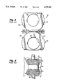
- FIG. 2 illustrates upper and lower rolls 112 and 114 of the type disclosed in U.S. Pat. No. 4,297,866.
- a plurality of disks 118 are laterally spaced on shaft 128 for intermeshing engagement with a plurality of offset disks 120, laterally spaced on shaft 130.
- the asymmetrically shaped teeth 132 have proved problematic in that it is difficult to obtain uniformly thin finished sheets.
- an upper preforming roll disk 218, in accordance with this invention (for use in place of disk 18), is shown to include a plurality of peripheral teeth 232, as well as a keyway 234 to enable the disk to be slidably mounted on a shaft 228 so as to precisely align a plurality of such disks 218 in side-by-side relation, with the apex of each tooth 232 aligned in rows extending parallel to the axis of the shaft 228.
- a lower roll of the roll pair is formed with identical teeth.
- FIG. 6 illustrates a preform/sitter disk 220 having a plurality of peripheral teeth 232 separated by slots 221. These slots 221 are intended to facilitate the slitting operation as roll 214 cooperates with a third roll in the cluster, such as that shown generally at 16 in FIG. 1.
- FIG. 7 the roll disk 218 is shown with one tooth 232 at maximum penetration of the strip S.
- an identical tooth of the lower roll has reached a point of maximum penetration in the opposite direction at alternate locations along the axes of the shafts or rolls as shown and described in the '443 patent.
- an entry angle A is defined by an entry surface of the tooth 232 and a tangent to the disk surface at a point of intersection of the tooth surface with the disk.
- a similar angle B is defined on the trailing side of the tooth 232 while a nose angle C is defined by the intersection of the tooth surfaces at the apex of the tooth.
- cutter teeth formed in accordance with the above calculations produce metal mesh strip which does not experience excessive elongation as in the past.
- the strip is more easily flattened to the required tolerance, and the subsequent pasting process may be carried out to achieve the required weight with greater precision.
Landscapes
- Engineering & Computer Science (AREA)
- Mechanical Engineering (AREA)
- Perforating, Stamping-Out Or Severing By Means Other Than Cutting (AREA)
- Turning (AREA)
- Cell Electrode Carriers And Collectors (AREA)
- Forging (AREA)
Abstract
Description
Claims (11)
Priority Applications (5)
| Application Number | Priority Date | Filing Date | Title |
|---|---|---|---|
| US08/143,785 US5375446A (en) | 1993-11-01 | 1993-11-01 | Rotary expanded grid cutter and related process |
| DE69414071T DE69414071T2 (en) | 1993-11-01 | 1994-04-29 | Rotating cutting device for the production of expanded metal and corresponding method |
| ES94250114T ES2123709T3 (en) | 1993-11-01 | 1994-04-29 | ROTARY CUTTER FOR CUTTING EXTENDED GRIDS AND RELATED PROCEDURE. |
| AT94250114T ATE172392T1 (en) | 1993-11-01 | 1994-04-29 | ROTATING CUTTING DEVICE FOR PRODUCING EXPANDED METAL AND CORRESPONDING METHOD |
| EP94250114A EP0650778B1 (en) | 1993-11-01 | 1994-04-29 | Rotary expanded grid cutter and related process |
Applications Claiming Priority (1)
| Application Number | Priority Date | Filing Date | Title |
|---|---|---|---|
| US08/143,785 US5375446A (en) | 1993-11-01 | 1993-11-01 | Rotary expanded grid cutter and related process |
Publications (1)
| Publication Number | Publication Date |
|---|---|
| US5375446A true US5375446A (en) | 1994-12-27 |
Family
ID=22505625
Family Applications (1)
| Application Number | Title | Priority Date | Filing Date |
|---|---|---|---|
| US08/143,785 Expired - Fee Related US5375446A (en) | 1993-11-01 | 1993-11-01 | Rotary expanded grid cutter and related process |
Country Status (5)
| Country | Link |
|---|---|
| US (1) | US5375446A (en) |
| EP (1) | EP0650778B1 (en) |
| AT (1) | ATE172392T1 (en) |
| DE (1) | DE69414071T2 (en) |
| ES (1) | ES2123709T3 (en) |
Cited By (5)
| Publication number | Priority date | Publication date | Assignee | Title |
|---|---|---|---|---|
| EP1004370A1 (en) * | 1998-11-23 | 2000-05-31 | Modine Manufacturing Company | Method and apparatus for roll forming a plurality of heat exchanger fin strips |
| US6167601B1 (en) * | 1995-09-22 | 2001-01-02 | Conrad American | Method for manufacturing ventilated sheet-metal floor members |
| US20050274012A1 (en) * | 2003-02-06 | 2005-12-15 | Emitec Gesellschaft Fur Emisionstechnologie Mbh | Method and tool for producing structured sheet metal layers, method for producing a metal honeycomb body, and catalyst carrier body |
| CN1322616C (en) * | 2002-08-09 | 2007-06-20 | 株式会社杰士汤浅 | Manufacturing method of grid body used for battery plate and manufacturing method of battery |
| US20120000264A1 (en) * | 2007-11-13 | 2012-01-05 | Hadley Industries Overseas Holdings Limited | Sheet material |
Citations (5)
| Publication number | Priority date | Publication date | Assignee | Title |
|---|---|---|---|---|
| US3760470A (en) * | 1971-02-08 | 1973-09-25 | Exmet Corp | Apparatus and method for producing expanded metal |
| US4291443A (en) * | 1978-10-31 | 1981-09-29 | Cominco Ltd. | Forming expanded mesh sheet from deformable strip |
| US4297866A (en) * | 1979-08-01 | 1981-11-03 | Cominco Ltd. | Asymmetrical shaping of slit segments of meshes formed in deformable strip |
| US5093971A (en) * | 1990-05-22 | 1992-03-10 | Exide Corporation | Method and apparatus for forming expanded mesh battery grid and grid formed therefrom |
| US5239735A (en) * | 1989-12-28 | 1993-08-31 | Matsushita Electric Industrial Co., Ltd. | Method for manufacturing expanded mesh sheet |
-
1993
- 1993-11-01 US US08/143,785 patent/US5375446A/en not_active Expired - Fee Related
-
1994
- 1994-04-29 AT AT94250114T patent/ATE172392T1/en active
- 1994-04-29 DE DE69414071T patent/DE69414071T2/en not_active Expired - Fee Related
- 1994-04-29 ES ES94250114T patent/ES2123709T3/en not_active Expired - Lifetime
- 1994-04-29 EP EP94250114A patent/EP0650778B1/en not_active Expired - Lifetime
Patent Citations (6)
| Publication number | Priority date | Publication date | Assignee | Title |
|---|---|---|---|---|
| US3760470A (en) * | 1971-02-08 | 1973-09-25 | Exmet Corp | Apparatus and method for producing expanded metal |
| US4291443A (en) * | 1978-10-31 | 1981-09-29 | Cominco Ltd. | Forming expanded mesh sheet from deformable strip |
| US4315356A (en) * | 1978-10-31 | 1982-02-16 | Cominco Ltd. | Forming expanded mesh sheet from deformable strip |
| US4297866A (en) * | 1979-08-01 | 1981-11-03 | Cominco Ltd. | Asymmetrical shaping of slit segments of meshes formed in deformable strip |
| US5239735A (en) * | 1989-12-28 | 1993-08-31 | Matsushita Electric Industrial Co., Ltd. | Method for manufacturing expanded mesh sheet |
| US5093971A (en) * | 1990-05-22 | 1992-03-10 | Exide Corporation | Method and apparatus for forming expanded mesh battery grid and grid formed therefrom |
Cited By (7)
| Publication number | Priority date | Publication date | Assignee | Title |
|---|---|---|---|---|
| US6167601B1 (en) * | 1995-09-22 | 2001-01-02 | Conrad American | Method for manufacturing ventilated sheet-metal floor members |
| EP1004370A1 (en) * | 1998-11-23 | 2000-05-31 | Modine Manufacturing Company | Method and apparatus for roll forming a plurality of heat exchanger fin strips |
| CN1322616C (en) * | 2002-08-09 | 2007-06-20 | 株式会社杰士汤浅 | Manufacturing method of grid body used for battery plate and manufacturing method of battery |
| US20050274012A1 (en) * | 2003-02-06 | 2005-12-15 | Emitec Gesellschaft Fur Emisionstechnologie Mbh | Method and tool for producing structured sheet metal layers, method for producing a metal honeycomb body, and catalyst carrier body |
| US8336176B2 (en) * | 2003-02-06 | 2012-12-25 | Emitec Gesellschaft Fuer Emissionstechnologie Mbh | Method and tool for producing structured sheet metal layers, method for producing a metal honeycomb body, and catalyst carrier body |
| US20120000264A1 (en) * | 2007-11-13 | 2012-01-05 | Hadley Industries Overseas Holdings Limited | Sheet material |
| US9138796B2 (en) * | 2007-11-13 | 2015-09-22 | Hadley Industries Overseas Holdings Limited | Sheet material |
Also Published As
| Publication number | Publication date |
|---|---|
| DE69414071D1 (en) | 1998-11-26 |
| EP0650778B1 (en) | 1998-10-21 |
| DE69414071T2 (en) | 1999-06-17 |
| ES2123709T3 (en) | 1999-01-16 |
| EP0650778A1 (en) | 1995-05-03 |
| ATE172392T1 (en) | 1998-11-15 |
Similar Documents
| Publication | Publication Date | Title |
|---|---|---|
| US3945097A (en) | Apparatus for making expanded metal lead-acid battery grids | |
| US3853626A (en) | Method and apparatus for making expanded metal lead-acid battery grids | |
| US4291443A (en) | Forming expanded mesh sheet from deformable strip | |
| US6944942B2 (en) | Apparatus for one-step rotary forming of uniform expanded mesh | |
| US3890160A (en) | Method and apparatus for preventing curling of lead strips during expansion | |
| CN112104175B (en) | Manufacturing process of motor stator core with straight tooth groove and special-shaped notch | |
| US3867200A (en) | Method and apparatus for making oxidized expanded lead battery grids | |
| US5375446A (en) | Rotary expanded grid cutter and related process | |
| EP0150913A2 (en) | Roller tooling for forming corrugated strip | |
| US4247970A (en) | Apparatus for forming expanded metal such as battery grids | |
| US3858428A (en) | Rolling of metal | |
| CN213918629U (en) | Cutting and pressing integrated machine | |
| EP1219364B1 (en) | Metal sheet perforating disk roll, metal sheet perforating device using the roll and metal sheet perforating method | |
| US7249546B1 (en) | Die-shaping apparatus and process and product formed thereby | |
| US4325272A (en) | Method of making saw blades | |
| JP3673073B2 (en) | Method and apparatus for producing spread mesh sheet | |
| US4848976A (en) | Laminated gear shaving tools | |
| Hein | Rotary expanded grid cutter and related process | |
| US716052A (en) | Sheet-metal-bending machine. | |
| JPS622882B2 (en) | ||
| JPH0280126A (en) | Method and apparatus for forming fin | |
| JPS6067015A (en) | Plate shearing apparatus | |
| JPS5924502A (en) | Multiple-piece rolling method of steel bar | |
| CN120228144A (en) | A rolling processing method | |
| JPS6016319A (en) | Inner ring gear type shaving cutter |
Legal Events
| Date | Code | Title | Description |
|---|---|---|---|
| AS | Assignment |
Owner name: EXIDE CORPORATION, PENNSYLVANIA Free format text: ASSIGNMENT OF ASSIGNORS INTEREST;ASSIGNOR:HEIN, EDWARD R.;REEL/FRAME:006907/0988 Effective date: 19931202 |
|
| AS | Assignment |
Owner name: CREDIT SUISSE FIRST BOSTON, ADMINISTRATIVE AGENT, Free format text: SECURITY INTEREST;ASSIGNOR:EXIDE CORPORATION (DE CORPORATION);REEL/FRAME:009138/0621 Effective date: 19980129 |
|
| FPAY | Fee payment |
Year of fee payment: 4 |
|
| REMI | Maintenance fee reminder mailed | ||
| FPAY | Fee payment |
Year of fee payment: 8 |
|
| SULP | Surcharge for late payment |
Year of fee payment: 7 |
|
| AS | Assignment |
Owner name: DEUTSCHE BANK AG NEW YORK, NEW YORK Free format text: SECURITY AGREEMENT;ASSIGNOR:EXIDE TECHNOLOGIES;REEL/FRAME:014683/0549 Effective date: 20040504 |
|
| AS | Assignment |
Owner name: EXIDE TECHNOLOGIES, GEORGIA Free format text: MERGER;ASSIGNORS:EXIDE CORPORATION;ETX TECHNOLOGIES, INC.;REEL/FRAME:016195/0438 Effective date: 20010716 |
|
| REMI | Maintenance fee reminder mailed | ||
| LAPS | Lapse for failure to pay maintenance fees | ||
| STCH | Information on status: patent discontinuation |
Free format text: PATENT EXPIRED DUE TO NONPAYMENT OF MAINTENANCE FEES UNDER 37 CFR 1.362 |
|
| FP | Lapsed due to failure to pay maintenance fee |
Effective date: 20061227 |