US5374800A - Method for welding of fuel rod - Google Patents
Method for welding of fuel rod Download PDFInfo
- Publication number
- US5374800A US5374800A US08/154,559 US15455993A US5374800A US 5374800 A US5374800 A US 5374800A US 15455993 A US15455993 A US 15455993A US 5374800 A US5374800 A US 5374800A
- Authority
- US
- United States
- Prior art keywords
- sealing material
- material body
- welding
- metal tube
- end plug
- Prior art date
- Legal status (The legal status is an assumption and is not a legal conclusion. Google has not performed a legal analysis and makes no representation as to the accuracy of the status listed.)
- Expired - Fee Related
Links
- 238000003466 welding Methods 0.000 title claims abstract description 62
- 239000000446 fuel Substances 0.000 title claims abstract description 34
- 238000000034 method Methods 0.000 title claims abstract description 31
- 239000003566 sealing material Substances 0.000 claims abstract description 29
- 239000000463 material Substances 0.000 claims abstract description 8
- 239000000203 mixture Substances 0.000 claims abstract 7
- 239000007789 gas Substances 0.000 claims description 15
- 239000011261 inert gas Substances 0.000 claims description 14
- 229910052751 metal Inorganic materials 0.000 claims description 12
- 239000002184 metal Substances 0.000 claims description 12
- 239000008188 pellet Substances 0.000 claims description 10
- 238000003825 pressing Methods 0.000 claims description 7
- 229910000881 Cu alloy Inorganic materials 0.000 claims description 3
- 229910001093 Zr alloy Inorganic materials 0.000 claims description 3
- XKRFYHLGVUSROY-UHFFFAOYSA-N Argon Chemical compound [Ar] XKRFYHLGVUSROY-UHFFFAOYSA-N 0.000 claims 8
- 229910052786 argon Inorganic materials 0.000 claims 4
- 239000001307 helium Substances 0.000 claims 4
- 229910052734 helium Inorganic materials 0.000 claims 4
- SWQJXJOGLNCZEY-UHFFFAOYSA-N helium atom Chemical compound [He] SWQJXJOGLNCZEY-UHFFFAOYSA-N 0.000 claims 4
- RYGMFSIKBFXOCR-UHFFFAOYSA-N Copper Chemical compound [Cu] RYGMFSIKBFXOCR-UHFFFAOYSA-N 0.000 claims 2
- 229910052802 copper Inorganic materials 0.000 claims 2
- 239000010949 copper Substances 0.000 claims 2
- 239000007772 electrode material Substances 0.000 abstract description 2
- 239000012535 impurity Substances 0.000 abstract 1
- WFKWXMTUELFFGS-UHFFFAOYSA-N tungsten Chemical compound [W] WFKWXMTUELFFGS-UHFFFAOYSA-N 0.000 description 10
- 229910052721 tungsten Inorganic materials 0.000 description 10
- 239000010937 tungsten Substances 0.000 description 10
- 230000000694 effects Effects 0.000 description 2
- 238000010438 heat treatment Methods 0.000 description 2
- 239000012080 ambient air Substances 0.000 description 1
- 239000011324 bead Substances 0.000 description 1
- 230000002925 chemical effect Effects 0.000 description 1
- 238000012790 confirmation Methods 0.000 description 1
- 238000001816 cooling Methods 0.000 description 1
- 238000005260 corrosion Methods 0.000 description 1
- 230000007797 corrosion Effects 0.000 description 1
- 238000000227 grinding Methods 0.000 description 1
- 238000002844 melting Methods 0.000 description 1
- 230000008018 melting Effects 0.000 description 1
- 238000012856 packing Methods 0.000 description 1
- 238000007789 sealing Methods 0.000 description 1
- 238000009834 vaporization Methods 0.000 description 1
- 230000008016 vaporization Effects 0.000 description 1
- XLYOFNOQVPJJNP-UHFFFAOYSA-N water Substances O XLYOFNOQVPJJNP-UHFFFAOYSA-N 0.000 description 1
Images
Classifications
-
- B—PERFORMING OPERATIONS; TRANSPORTING
- B23—MACHINE TOOLS; METAL-WORKING NOT OTHERWISE PROVIDED FOR
- B23K—SOLDERING OR UNSOLDERING; WELDING; CLADDING OR PLATING BY SOLDERING OR WELDING; CUTTING BY APPLYING HEAT LOCALLY, e.g. FLAME CUTTING; WORKING BY LASER BEAM
- B23K11/00—Resistance welding; Severing by resistance heating
- B23K11/08—Seam welding not restricted to one of the preceding subgroups
- B23K11/093—Seam welding not restricted to one of the preceding subgroups for curved planar seams
- B23K11/0935—Seam welding not restricted to one of the preceding subgroups for curved planar seams of tube sections
-
- B—PERFORMING OPERATIONS; TRANSPORTING
- B23—MACHINE TOOLS; METAL-WORKING NOT OTHERWISE PROVIDED FOR
- B23K—SOLDERING OR UNSOLDERING; WELDING; CLADDING OR PLATING BY SOLDERING OR WELDING; CUTTING BY APPLYING HEAT LOCALLY, e.g. FLAME CUTTING; WORKING BY LASER BEAM
- B23K2101/00—Articles made by soldering, welding or cutting
- B23K2101/04—Tubular or hollow articles
- B23K2101/06—Tubes
Definitions
- the present invention relates to a technique of resistance welding of a seal opening provided on an end plug of a fuel rod containing fuel pellets and pressurized to a specific gaseous pressure with an inert gas filled through the seal opening.
- a fuel rod for use in a light water pressurized reactor is made by packing fuel pellets inside a fuel tube, and the ends of the fuel tube are fitted with end plugs and the end plugs are joined to the ends of the fuel tube by means of joining techniques such as the tungsten inert gas (TIG) welding. Further, there is a (gas) seal opening disposed on one of the two end plugs for filling the fuel tube interior with an inert gas under pressure. The gas seal opening is sealed off, by joining methods such as TIG welding, so as to maintain the gaseous pressure of the fuel tube at a specific value.
- joining techniques such as the tungsten inert gas (TIG) welding.
- TIG tungsten inert gas
- TIG welding for general welding applications is performed in an open atmospheric pressure, and an inert gas is circulated so as to protect the tungsten electrode and the object to be welded from the chemical effects of the ambient air atmosphere, and to provide cooling.
- the present invention was made in view of the technical problems described above, by developing a method for resistance welding in a welding chamber of a gas seal opening provided on an end plug, comprising the steps of: (a) pressing a sealing material body against the gas seal opening; and (b) passing a current through contact electrodes disposed on the sealing material body and on the fuel tube so as to heat a joint between the sealing material body and the end plug to cause resistance welding of the joint.
- welding is performed while Dressing a sealing material body, preferably made of the same material as the end plug, against the gas seal opening of the end plug, and passing a current between the end plug and the sealing material body, thereby heating the end plug and the sealing material body by specific resistance and contact resistance heating effects.
- the temperature rises until the joint is hot enough to form a metallurgical bond between the end plug and the sealing material body, and due to the pressing applied, resistance welding of the joint is achieved smoothly.
- the technique allows the welding to be performed, even under the condition of an inert gaseous pressure, stably in terms of the bead position and the melt-in shape, and enables to continuously weld a plurality of end plugs.
- the technique is further superior to the conventional TIG welding because it enables to eliminate shape adjustments of the tungsten electrode and gap setting between the tungsten electrode and the end plug before undertaking every welding operation.
- a further feature of the invented welding method is that it enables automation of the welding process of the fuel rod.
- a preferred method is to include the steps wherein prior to the steps (a) and (b), the fuel tube is readied for loading fuel pellets, and is loaded with a plurality of fuel pellets.
- the method of resistance welding is thus able to eliminate the danger of including the electrode material such as tungsten in the welded metal; to eliminate the necessity for operational adjustments and confirmation required before undertaking each welding operation, such as adjusting the arc gap and reshaping of the electrode which were required in the conventional TIG welding.
- the welding is conducted in a chamber filled with an inert gas to a specific gaseous pressure which is equalized through the gas seal opening with the inner gaseous pressure of the fuel tube.
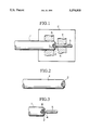
- FIG. 1 is illustration of the pressing-assisted resistance welding method of the present invention.
- FIG. 2 is an illustration of the fuel rod after the completion of the welding process.
- FIG. 3 is a variation of the first embodiment in which the welding end of the sealing material body is shaped to provide a plane contact with the conical gas seal opening.
- FIGS. 1 and 2 A first embodiment of the present invention will be explained with reference to FIGS. 1 and 2.
- the reference numeral 1 refers to a fuel tube for making a fuel rod which houses pellets and a coil spring.
- an end plug 2 is inserted and joined to the tube by welding the peripheries.
- a (gas) seal opening 3 is formed on the upper end plug of the above two end plugs 2 for the fuel rod, and the exterior shape of the seal opening 3 is a conical opening 4 so as to enlarge its diameter as it extends outward away from the fuel rod.
- the fuel rod of the above configuration is welded in a welding chamber C as follows. First, an inert gas He is charged into the fuel tube 1 from the seal opening 3 of the one end plug 2. Then, as shown in FIG. 1, a sealing material body 5 of a wire or rod shape, made of zircalloy which is the same material as the one end plug 2, is pushed up against the conical opening 4. The diameter of the wire 5, such as 2 mm diameter, is chosen so as to permit the wire 5 to be in contact with the conical opening 4.
- the vicinities of the end plug 2 and the wire 5 are clamped with contact electrodes 6, 7 made of such materials as copper alloys, and a large current is passed through. Then, while pressing the contact electrodes 6, 7 towards each other, the end plug 2 and the wire 5 are heated by the specific and contact resistance effects at the joint, and the temperature rises to induce welding in the joint region.
- the wire 5 is resistance welded with assistance from the force of pressing in the conical opening 4 so as to weld to the conical opening 4 to seal the gas seal opening 3, thus sealing the fuel rod under a specific gaseous pressure of the inert gas He maintained in the welding chamber C.
- the excess wire 5 is cut off to complete the welding operation as shown in FIG. 2.
- the wire 5 is forwarded by such method as pinch rollers to supply the wire for the next welding operation.
Landscapes
- Engineering & Computer Science (AREA)
- Mechanical Engineering (AREA)
- Butt Welding And Welding Of Specific Article (AREA)
- Arc Welding In General (AREA)
Abstract
A resistance welding method for a fuel rod is presented in which the gas seal opening is closed with a sealing material of the same composition as the end plug material. The method enable to perform welding stably in a pressurized welding chamber, and the process is amenable to automation. The sealing material body is made of a wire, and is pressed against the conical shaped opening provided on the end plug. The welding method avoids contaminating the weld with undesirable impurities from the electrode material, and the welding operations is designed so that there is no need to reshape the end of the electrode or adjust the gap between the sealing material and the seal opening.
Description
1. Field of the Invention
The present invention relates to a technique of resistance welding of a seal opening provided on an end plug of a fuel rod containing fuel pellets and pressurized to a specific gaseous pressure with an inert gas filled through the seal opening.
2. Technical Background
In general, a fuel rod for use in a light water pressurized reactor is made by packing fuel pellets inside a fuel tube, and the ends of the fuel tube are fitted with end plugs and the end plugs are joined to the ends of the fuel tube by means of joining techniques such as the tungsten inert gas (TIG) welding. Further, there is a (gas) seal opening disposed on one of the two end plugs for filling the fuel tube interior with an inert gas under pressure. The gas seal opening is sealed off, by joining methods such as TIG welding, so as to maintain the gaseous pressure of the fuel tube at a specific value.
TIG welding for general welding applications is performed in an open atmospheric pressure, and an inert gas is circulated so as to protect the tungsten electrode and the object to be welded from the chemical effects of the ambient air atmosphere, and to provide cooling.
However, because the welding of the seal opening of a fuel rod must be carried out in a pressurized welding chamber, it is difficult to flow the inert gas between the welding object and the tungsten electrode. It is also difficult to generate the welding arc in the pressurized welding chamber, and it is often necessary to overheat the electrode in the initial stage of the welding operation. Accordingly, when performing TIG welding in a pressurized welding chamber, there is a rapid wear of the tungsten electrode, and depending on the welding conditions, there is a danger of inclusion of the tungsten in the metal of the weld. It is not desirable that tungsten becomes mixed in the weld, because when it happens, the weld quality becomes degraded, for example, by the loss of the corrosion resistance of the weld. Therefore, it was necessary that the welding operation be carried out with utmost care. The tungsten electrode suffered shape changes after each welding operation, due to such factors as melting and vaporization of part of the electrode, thus necessitating adjustments in the arc gap for every welding as well as frequent exchanging of the electrode for grinding of the electrode so as to reshape the tip to the required shape.
The present invention was made in view of the technical problems described above, by developing a method for resistance welding in a welding chamber of a gas seal opening provided on an end plug, comprising the steps of: (a) pressing a sealing material body against the gas seal opening; and (b) passing a current through contact electrodes disposed on the sealing material body and on the fuel tube so as to heat a joint between the sealing material body and the end plug to cause resistance welding of the joint.
According to the welding method of the invention, welding is performed while Dressing a sealing material body, preferably made of the same material as the end plug, against the gas seal opening of the end plug, and passing a current between the end plug and the sealing material body, thereby heating the end plug and the sealing material body by specific resistance and contact resistance heating effects. The temperature rises until the joint is hot enough to form a metallurgical bond between the end plug and the sealing material body, and due to the pressing applied, resistance welding of the joint is achieved smoothly.
The technique allows the welding to be performed, even under the condition of an inert gaseous pressure, stably in terms of the bead position and the melt-in shape, and enables to continuously weld a plurality of end plugs. The technique is further superior to the conventional TIG welding because it enables to eliminate shape adjustments of the tungsten electrode and gap setting between the tungsten electrode and the end plug before undertaking every welding operation. A further feature of the invented welding method is that it enables automation of the welding process of the fuel rod.
A preferred method is to include the steps wherein prior to the steps (a) and (b), the fuel tube is readied for loading fuel pellets, and is loaded with a plurality of fuel pellets.
The method of resistance welding is thus able to eliminate the danger of including the electrode material such as tungsten in the welded metal; to eliminate the necessity for operational adjustments and confirmation required before undertaking each welding operation, such as adjusting the arc gap and reshaping of the electrode which were required in the conventional TIG welding.
In a further embodiment of the invention, the welding is conducted in a chamber filled with an inert gas to a specific gaseous pressure which is equalized through the gas seal opening with the inner gaseous pressure of the fuel tube.
Through the embodiment of the invention, stable continuous welding can be obtained even under pressurization.
FIG. 1 is illustration of the pressing-assisted resistance welding method of the present invention.
FIG. 2 is an illustration of the fuel rod after the completion of the welding process.
FIG. 3 is a variation of the first embodiment in which the welding end of the sealing material body is shaped to provide a plane contact with the conical gas seal opening.
A first embodiment of the present invention will be explained with reference to FIGS. 1 and 2.
In the figures, the reference numeral 1 refers to a fuel tube for making a fuel rod which houses pellets and a coil spring. At each end of the fuel tube 1, an end plug 2 is inserted and joined to the tube by welding the peripheries. A (gas) seal opening 3 is formed on the upper end plug of the above two end plugs 2 for the fuel rod, and the exterior shape of the seal opening 3 is a conical opening 4 so as to enlarge its diameter as it extends outward away from the fuel rod.
The fuel rod of the above configuration is welded in a welding chamber C as follows. First, an inert gas He is charged into the fuel tube 1 from the seal opening 3 of the one end plug 2. Then, as shown in FIG. 1, a sealing material body 5 of a wire or rod shape, made of zircalloy which is the same material as the one end plug 2, is pushed up against the conical opening 4. The diameter of the wire 5, such as 2 mm diameter, is chosen so as to permit the wire 5 to be in contact with the conical opening 4. To be able to flow a large amount of current (example, several thousand amperes) concentrated in the pressed region, the vicinities of the end plug 2 and the wire 5 are clamped with contact electrodes 6, 7 made of such materials as copper alloys, and a large current is passed through. Then, while pressing the contact electrodes 6, 7 towards each other, the end plug 2 and the wire 5 are heated by the specific and contact resistance effects at the joint, and the temperature rises to induce welding in the joint region. Accordingly, due to the pressing force exerted on the joint region, the wire 5 is resistance welded with assistance from the force of pressing in the conical opening 4 so as to weld to the conical opening 4 to seal the gas seal opening 3, thus sealing the fuel rod under a specific gaseous pressure of the inert gas He maintained in the welding chamber C. When the above resistance welding operation is completed, the excess wire 5 is cut off to complete the welding operation as shown in FIG. 2. The wire 5 is forwarded by such method as pinch rollers to supply the wire for the next welding operation. Therefore, it becomes possible not only to perform every welding operation using the freshly cut surface of a wire 5, but also to use a long length of wire 5, thus enabling to weld a plurality of end plugs 2 continuously under stable welding conditions, thus opening a way to automating the welding process.
In a variation of the first embodiment, it is also possible to shape the end of the wire 2 so as to provide a corresponding conical plane 8 for plane contact between the wire 5 and the conical opening 4 as illustrated in FIG. 3. By utilizing such a configurational arrangement, it provides a wider range of flexibility in the choice of joining conditions.
The present application claims the priority of Japanese patent application filed in Japan, No. H04-312467, on Nov. 20, 1992, which is herein incorporated by reference.
Claims (20)
1. A method for resistance welding of a gas seal opening provided on an end plug of a fuel rod, comprising the steps of:
(a) providing a fuel rod comprising a metal tube which houses pellets and a coil spring, and a pair of end plugs fixed in both ends of said metal tube, one of said end plugs having a gas seal opening formed through said end plug, and said gas seal opening containing a conical opening formed in an end thereof so as to enlarge its inner diameter as it extends outward away from said metal tube;
(b) providing a sealing material body having a constant diameter being smaller than a maximum diameter of said conical opening and being larger then a minimum diameter of said conical opening;
(c) pressing the sealing material body against said conical opening coaxially to each other;
(d) passing a current through contact electrodes disposed on said sealing material body and on said metal tube so as to heat a joint between said sealing material body and said end plug, to cause resistance welding of said joint; and
(e) cutting said sealing material body perpendicularly to center axis thereof.
2. A method as claimed in claim 1, wherein prior to steps (a) and (b), the metal tube is readied for loading fuel pellets, and is loaded with a plurality of fuel pellets, and is filled with an inert gas.
3. A method as claimed in claim 2, wherein said inert gas is selected from the group consisting of helium, argon and a mixture of helium and argon.
4. A method as claimed in either one of claims 1 or 2, wherein said method for resistance welding is carried out in a welding chamber filled with an inert gas to a specific gaseous pressure.
5. A method as claimed in claim 4, wherein said specific gaseous pressure is not less than one atmospheric pressure.
6. A method as claimed in claim 1, wherein said sealing material body is made of a material of a same composition as a composition of the end plug.
7. A method as claimed in claim 1, wherein said sealing material body is made of zircalloy.
8. A method of claimed in claim 1, wherein said sealing material body is a wire.
9. A method as claimed in claim 1, wherein said contact electrodes are made of a material selected from the group consisting of copper and copper alloys.
10. A method as claimed in claim 1, wherein the welding end of said sealing material body is shaped to correspond with a shape of said conical opening in advance.
11. A system for resistance welding of a gas seal opening provided on an end plug of a fuel rod, comprising:
a fuel rod comprising a metal tube which houses pellets and a coil spring, and a pair of end plugs fixed in both ends of said metal tube, one of said end plugs having a gas seal opening formed through said end plug, and said gas seal opening containing a conical opening formed in an end thereof so as to enlarge its inner diameter as it extends outward away from said metal tube;
a sealing material body having a constant diameter being smaller than a maximum diameter of said conical opening and being larger then a minimum diameter of said conical opening, wherein the sealing material body is pressed against said conical opening coaxially to each other;
a current passing through contact electrodes disposed on said sealing material body and on said metal tube so as to heat a joint between said sealing material body and said end plug, to cause resistance welding of said joint.
12. A system as claimed in claim 11, wherein the metal tube is loaded with a plurality of fuel pellets and is filled with an inert gas.
13. A system as claimed in claim 12, wherein said inert gas is selected from the group selecting of helium, argon and a mixture of helium and argon.
14. A system as claimed in either one of claims 11 or 12, wherein said resistance welding is carried out in a welding chamber filled with an inert gas to a specific gaseous pressure.
15. A system as claimed in claim 14, wherein said specific gaseous pressure is not less than one atmospheric pressure.
16. A system as claimed in claim 11, wherein said sealing material body is made of a material of a same composition as a composition of the end plug.
17. A system as claimed in claim 11, wherein said sealing material body is made of zircalloy.
18. A system of claimed in claim 11, wherein said sealing material body is a wire.
19. A system as claimed in claim 11, wherein said contact electrodes are made of a material selected from the group consisting of copper and copper alloys.
20. A system as claimed in claim 11, wherein the welding end of said sealing material body is shaped to correspond with a shape of said conical opening in advance.
Applications Claiming Priority (2)
| Application Number | Priority Date | Filing Date | Title |
|---|---|---|---|
| JP31246792A JP3183732B2 (en) | 1992-11-20 | 1992-11-20 | Fuel rod pressure welding method |
| JP4-312467 | 1992-11-20 |
Publications (1)
| Publication Number | Publication Date |
|---|---|
| US5374800A true US5374800A (en) | 1994-12-20 |
Family
ID=18029555
Family Applications (1)
| Application Number | Title | Priority Date | Filing Date |
|---|---|---|---|
| US08/154,559 Expired - Fee Related US5374800A (en) | 1992-11-20 | 1993-11-19 | Method for welding of fuel rod |
Country Status (2)
| Country | Link |
|---|---|
| US (1) | US5374800A (en) |
| JP (1) | JP3183732B2 (en) |
Cited By (9)
| Publication number | Priority date | Publication date | Assignee | Title |
|---|---|---|---|---|
| US5906756A (en) * | 1996-05-11 | 1999-05-25 | Samsung Electronics Co., Ltd. | Method of making balancing device for a drum washing machine |
| US20040035833A1 (en) * | 2002-08-22 | 2004-02-26 | Venkatasubramanian Ananthanarayanan | Method for metallurgically joining a tube to a member |
| US20050194360A1 (en) * | 2003-05-06 | 2005-09-08 | Delphi Technologies Inc. | Method for resistance welding/brazing a tube to a member |
| US20060006148A1 (en) * | 2004-07-07 | 2006-01-12 | Ananthanarayanan Venkatasubram | Welding apparatus for resistance welding heat exchanger tube to tubesheet |
| US20060006147A1 (en) * | 2004-07-07 | 2006-01-12 | Ananthanarayanan Venkatasubram | Method for welding heat exchanger tube to tubesheet |
| US20090114623A1 (en) * | 2004-07-23 | 2009-05-07 | Delphi Technologies, Inc. | Method for welding employing current |
| US9922731B2 (en) | 2012-04-17 | 2018-03-20 | Bwxt Mpower, Inc. | Resistance welding of an end cap for nuclear fuel rods |
| US10410754B2 (en) | 2016-10-11 | 2019-09-10 | Bwxt Mpower, Inc. | Resistance pressure weld for nuclear reactor fuel rod tube end plug |
| US11881322B2 (en) | 2017-10-19 | 2024-01-23 | General Atomics | Joining and sealing pressurized ceramic structures |
Families Citing this family (1)
| Publication number | Priority date | Publication date | Assignee | Title |
|---|---|---|---|---|
| RU2603355C1 (en) * | 2015-11-26 | 2016-11-27 | Российская Федерация, от имени которой выступает Государственная корпорация по атомной энергии "Росатом" | Sealing method of nuclear reactor fuel elements with high-chromium steel shell |
Citations (6)
| Publication number | Priority date | Publication date | Assignee | Title |
|---|---|---|---|---|
| US3842238A (en) * | 1970-12-08 | 1974-10-15 | Westinghouse Electric Corp | Method of sealing nuclear fuel elements by electric welding |
| US3952395A (en) * | 1974-12-30 | 1976-04-27 | Goodyear Aerospace Corporation | Method of closing the end of a drilled passage |
| US4003788A (en) * | 1970-12-08 | 1977-01-18 | Westinghouse Electric Corporation | Nuclear fuel elements sealed by electric welding |
| US4097712A (en) * | 1975-11-07 | 1978-06-27 | Kraftwerk Union Aktiengesellschaft | Method of joining nuclear fuel rod end caps and nuclear fuel rod cladding tubes |
| US4106171A (en) * | 1974-11-29 | 1978-08-15 | Hughes Aircraft Company | Method for closure of heat pipes and device fabricated thereby |
| US5251247A (en) * | 1989-05-09 | 1993-10-05 | Abb Atom A.B. | Method of sealing a fuel rod by welding |
-
1992
- 1992-11-20 JP JP31246792A patent/JP3183732B2/en not_active Expired - Fee Related
-
1993
- 1993-11-19 US US08/154,559 patent/US5374800A/en not_active Expired - Fee Related
Patent Citations (6)
| Publication number | Priority date | Publication date | Assignee | Title |
|---|---|---|---|---|
| US3842238A (en) * | 1970-12-08 | 1974-10-15 | Westinghouse Electric Corp | Method of sealing nuclear fuel elements by electric welding |
| US4003788A (en) * | 1970-12-08 | 1977-01-18 | Westinghouse Electric Corporation | Nuclear fuel elements sealed by electric welding |
| US4106171A (en) * | 1974-11-29 | 1978-08-15 | Hughes Aircraft Company | Method for closure of heat pipes and device fabricated thereby |
| US3952395A (en) * | 1974-12-30 | 1976-04-27 | Goodyear Aerospace Corporation | Method of closing the end of a drilled passage |
| US4097712A (en) * | 1975-11-07 | 1978-06-27 | Kraftwerk Union Aktiengesellschaft | Method of joining nuclear fuel rod end caps and nuclear fuel rod cladding tubes |
| US5251247A (en) * | 1989-05-09 | 1993-10-05 | Abb Atom A.B. | Method of sealing a fuel rod by welding |
Cited By (22)
| Publication number | Priority date | Publication date | Assignee | Title |
|---|---|---|---|---|
| US5906756A (en) * | 1996-05-11 | 1999-05-25 | Samsung Electronics Co., Ltd. | Method of making balancing device for a drum washing machine |
| US6998560B2 (en) | 2002-08-22 | 2006-02-14 | Delphi Technologies, Inc. | Method for metallurgically joining a tube to a member |
| US20040035833A1 (en) * | 2002-08-22 | 2004-02-26 | Venkatasubramanian Ananthanarayanan | Method for metallurgically joining a tube to a member |
| US20040035504A1 (en) * | 2002-08-22 | 2004-02-26 | Venkatasubramanian Ananthanarayanan | Method for joining a tube to a member |
| US20040035834A1 (en) * | 2002-08-22 | 2004-02-26 | Venkatasubramanian Ananthanarayanan | Method for metallurgically joining a tube to a member |
| US20040035832A1 (en) * | 2002-08-22 | 2004-02-26 | Venkatasubramanian Ananthanarayanan | Method for metallurgically joining a tube to a member |
| WO2004019374A3 (en) * | 2002-08-22 | 2004-05-13 | Delphi Tech Inc | Method for metallurgically joining a tube to a member |
| US6847001B2 (en) | 2002-08-22 | 2005-01-25 | Delphi Technologies, Inc. | Method for metallurgically joining a tube to a member |
| US6953147B2 (en) | 2002-08-22 | 2005-10-11 | Delphi Technologies, Inc. | Method for joining a tube to a member |
| US6953907B2 (en) | 2002-08-22 | 2005-10-11 | Delphi Technologies, Inc. | Method for metallurgically joining a tube to a member |
| US20050194360A1 (en) * | 2003-05-06 | 2005-09-08 | Delphi Technologies Inc. | Method for resistance welding/brazing a tube to a member |
| US7423232B2 (en) | 2003-05-06 | 2008-09-09 | Delphi Technologies, Inc. | Method for resistance welding/brazing a tube to a member |
| US20060006148A1 (en) * | 2004-07-07 | 2006-01-12 | Ananthanarayanan Venkatasubram | Welding apparatus for resistance welding heat exchanger tube to tubesheet |
| US7253372B2 (en) | 2004-07-07 | 2007-08-07 | Delphi Technologies, Inc. | Method for welding heat exchanger tube to tubesheet |
| US20060006147A1 (en) * | 2004-07-07 | 2006-01-12 | Ananthanarayanan Venkatasubram | Method for welding heat exchanger tube to tubesheet |
| US7476824B2 (en) | 2004-07-07 | 2009-01-13 | Delphi Technologies, Inc. | Welding apparatus for resistance welding heat exchanger tube to tubesheet |
| US20090114623A1 (en) * | 2004-07-23 | 2009-05-07 | Delphi Technologies, Inc. | Method for welding employing current |
| US9922731B2 (en) | 2012-04-17 | 2018-03-20 | Bwxt Mpower, Inc. | Resistance welding of an end cap for nuclear fuel rods |
| US10410754B2 (en) | 2016-10-11 | 2019-09-10 | Bwxt Mpower, Inc. | Resistance pressure weld for nuclear reactor fuel rod tube end plug |
| US11049623B2 (en) | 2016-10-11 | 2021-06-29 | Bwxt Mpower, Inc. | Resistance pressure weld for nuclear reactor fuel rod tube end plug |
| US12417854B2 (en) | 2016-10-11 | 2025-09-16 | Bwxt Mpower, Inc. | Resistance pressure weld for nuclear reactor fuel rod tube end plug |
| US11881322B2 (en) | 2017-10-19 | 2024-01-23 | General Atomics | Joining and sealing pressurized ceramic structures |
Also Published As
| Publication number | Publication date |
|---|---|
| JP3183732B2 (en) | 2001-07-09 |
| JPH06160589A (en) | 1994-06-07 |
Similar Documents
| Publication | Publication Date | Title |
|---|---|---|
| US5374800A (en) | Method for welding of fuel rod | |
| US2053417A (en) | Arc welding apparatus | |
| KR20000029905A (en) | Method of welding | |
| EP1694460B1 (en) | Process for welding | |
| US5990441A (en) | Damper tube closure | |
| US2902587A (en) | Arc welding process and apparatus | |
| AU734722B2 (en) | Method of manufacturing metal tubes | |
| EP0005945B1 (en) | Method of welding metal parts | |
| US20090114623A1 (en) | Method for welding employing current | |
| US6689981B1 (en) | Method for metallurgically capping an end of a tube | |
| US4204378A (en) | Method of closing a capillary tube | |
| US4542843A (en) | Method of friction welding a lamp feedthrough assembly | |
| US2760044A (en) | Method of arc welding | |
| US1728863A (en) | Electric-arc welding | |
| US6875944B2 (en) | Method for resistance welding/brazing a tube to a container | |
| US3528166A (en) | Process for the welding of metal objects | |
| US5401933A (en) | Method for welding of end plug of control rod | |
| WO2017044722A1 (en) | Surface preparation and resistance welding apparatus for aluminium | |
| EP0657912A2 (en) | Process for connection of a molybdenum foil to a molybdenum lead portion and method of producing a hermetically enclosed part of a lamp using the process | |
| US4558202A (en) | Weldment for austenitic stainless steel and method | |
| US4287746A (en) | Device for closing a metallic tube | |
| US4661739A (en) | Welded tungsten filament to lead joint | |
| JP7155816B2 (en) | Manufacturing method and welding equipment for austenitic stainless steel pipe welded joint | |
| JPH113727A (en) | Apparatus and method for reducing pressure of sodium-sulfur battery | |
| JPH1024320A (en) | Manufacturing method of steel pipe |
Legal Events
| Date | Code | Title | Description |
|---|---|---|---|
| AS | Assignment |
Owner name: MITSUBISHI NUCLEAR FUEL CO., JAPAN Free format text: ASSIGNMENT OF ASSIGNORS INTEREST;ASSIGNOR:YONEDA, EIJI;REEL/FRAME:007152/0285 Effective date: 19931105 |
|
| FEPP | Fee payment procedure |
Free format text: PAYOR NUMBER ASSIGNED (ORIGINAL EVENT CODE: ASPN); ENTITY STATUS OF PATENT OWNER: LARGE ENTITY |
|
| FPAY | Fee payment |
Year of fee payment: 4 |
|
| REMI | Maintenance fee reminder mailed | ||
| LAPS | Lapse for failure to pay maintenance fees | ||
| STCH | Information on status: patent discontinuation |
Free format text: PATENT EXPIRED DUE TO NONPAYMENT OF MAINTENANCE FEES UNDER 37 CFR 1.362 |
|
| FP | Lapsed due to failure to pay maintenance fee |
Effective date: 20021220 |