US536960A - Magazine-firearm - Google Patents
Magazine-firearm Download PDFInfo
- Publication number
- US536960A US536960A US536960DA US536960A US 536960 A US536960 A US 536960A US 536960D A US536960D A US 536960DA US 536960 A US536960 A US 536960A
- Authority
- US
- United States
- Prior art keywords
- magazine
- transfer
- stock
- gun
- lever
- Prior art date
- Legal status (The legal status is an assumption and is not a legal conclusion. Google has not performed a legal analysis and makes no representation as to the accuracy of the status listed.)
- Expired - Lifetime
Links
Images



Classifications
-
- F—MECHANICAL ENGINEERING; LIGHTING; HEATING; WEAPONS; BLASTING
- F41—WEAPONS
- F41C—SMALLARMS, e.g. PISTOLS, RIFLES; ACCESSORIES THEREFOR
- F41C7/00—Shoulder-fired smallarms, e.g. rifles, carbines, shotguns
- F41C7/06—Lever-action guns, i.e. guns having a rocking lever for loading or cocking
-
- F—MECHANICAL ENGINEERING; LIGHTING; HEATING; WEAPONS; BLASTING
- F41—WEAPONS
- F41A—FUNCTIONAL FEATURES OR DETAILS COMMON TO BOTH SMALLARMS AND ORDNANCE, e.g. CANNONS; MOUNTINGS FOR SMALLARMS OR ORDNANCE
- F41A3/00—Breech mechanisms, e.g. locks
- F41A3/02—Block action, i.e. the main breech opening movement being transverse to the barrel axis
- F41A3/10—Block action, i.e. the main breech opening movement being transverse to the barrel axis with sliding breech-block, e.g. vertically
Definitions
- Myinvention herein described and shown relates to improvements in the magazine gun described and shown in my application, Serial No. 455,004, filed December 5, 1892.
- the objects of my invention are, first, to provide a magazine gun with which the cartridge maybe stored at the butt of the stock, and transferred thence to the barrel without the use of a spiral spring back of them; second, to provide for transferring each cartridge from the magazine at the butt of the stock to the breech of the barrel independent of the other and in such a manner that no two cartridges can come in contact after leaving the magazine; third, to provide a detachable magazine for breech-loading guns; fourth, to provide a safety device whereby my gun may be loaded and cooked without danger of firing, except when desired, and, fifth, to provide for throwing the hammer back a short distance, and freeing the firing pin as soon as the gun has been fired.
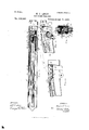
- Figure 1 is a longitudinal vertical section of my gun stock. with the magazine in place and filled with cartridges, and the transfer tube in longitudinal section, with cartridges, and the transfer mechanism in place to carry the cartridgesforward to the barrel.
- Figure 2 is a side view of my main spring.
- Fig. 3 is a bottom plan of my main lever, showing the arm that operates the transfer mechanism.
- Fig. at is a front elevation of the breech block showing the position of the hammer, and the ends of the breech block lever.
- Fig. 5 is a top plan of the breech block lever.
- Fig. 6 is a longitudinal vertical section of my stock with the magazine, and part of the transfer tube removed and the breech block thrown to place.
- Fig. 7 is a detail plan and a side elevation of the mechanism that transmits motion from the main lever to the transfer mechanism, showing the connecting bar, the pinions,
- Fig. 8 is a bottom plan, and a side elevation of the mechanism that transfers the cartridges through the second, third and fifth stages of their course from the magazine to the gun-barrel, and draws the shell from the gun-barrel when it is desired to replace it with a new cartridge.
- Fig. 9 is a top plan and a side elevation of the mechanism that carries the cartridge through the fourth stage of its course from the magazine to the gun barrel, prevents the cartridge from falling out of the transfer tube when passing through the fifth stage, and expels the shell from the tube when it has been drawn back out of the gun barrel.
- Fig. 10 is a transverse longitudinal section of the gun stock showing a plan of the transfer mechanism, the breech block, the hammer, the lever, and the transfer tube, but with the magazine proper removed.
- Fig. 11 is an elevation of the end of the gun-stock, next to the barrel, partly in section, to show the gun cooked, the position of the safety lever, and the position of the shell extractor when the cartridge is in the barrel and the breech block is up to place.
- Fig. 12, is the same, simply showing the action of the shell expelling device when the extractor has drawn the shell clear of the gun barrel.
- Fig. 13 is a vertical cross section of the gun stock on the line 00 0c of Figs.
- Fig. 14 is a side elevation of my magazine with cartridges in one side only, and a short section of the transfer tube to show the manner of telescoping the tube of the magazine into the transfer tube.
- Fig. 15 is an end elevation of the same showing the position of the butts of the cartridges in outline, and also the elastic or spring that forces them through the magazine and into the transfer tube.
- Fig. 16 is a vertical section of the butt of the gun stock showing a single row magazine with a steel spring for forcing the cartridges into the transfer tube.
- Fig. 17, is the same showing the spring attached to the stock independent of the magazine.
- Fig. 18 is a vertical cross section of the butt of the stock showing my single line magazine in position, and the butt ends of the cartridges in outline.
- Fig. 19, is a face view of IOC the trigger and Fig. 20, is a side elevation of my gun showing the removable stock plate.
- A is the stock of my gun which I construct of any suitable thin material, preferably of aluminum, and which I make hollow its entire length for the reception of the magazine, the transfer mechanism, the breech block and the hammer.
- B represents a short piece of the gun barrel.
- breech plate that supports the gun barrel. It is made open below the barrel, as
- breech block D is the breech block, the upper end of which is fitted for the reception of the firing pin F and the lower end is fitted for receiving and supporting the hammer E and the ends 71 of the breech block lever H, as shown in Figs. 1 and 1, and indicated in Fig. 6.
- the hammerE is made substantially of the form shown in Figs. 1 and 6, and is pivoted to the breech block upon the bolt 6, with the forward end d projecting into the opening 0 in the lower end of the breech plate, di-
- My device for throwing the hammer back and freeing the firing pin consists of a peculiarly curved projection G upon the end of the main spring so constructed that the rebound of the main spring willthrow the hammer with sufficient force to slightly raise this projection and throw the firing pin against the cartridge priming and fire the cartridge, when the rebound of the projection will throw the hammer back just sufficiently to free th firing pin, as shown in Fig. 6. 1
- My slotted cam H an elevation of which is shown in Figs. 1 and 6, is formed with two exactly similar bodies connected by a small neck h" as shown in Fig. 5, and indicated by the dotted lines It in Fig. 1.
- This lever is provided with a slotted cam H that passes through both sides, and is fitted to receive the small antifriction rollers Z, at the end of the arm L, of the main lever and is of such a form that when the main lever is thrown down far enough to carry the rollers Z, Z, to the point It, the breech block will be thrown down to the position shown in Fig. 1; the slot from h to it being simplyfor the free passage of the rollers, and of such a form that the rollers in passing to position at h, as in Fig. 1, will lock the lever to place and avert all danger of the breech block moving, regardless of the position in which the gun is held.
- the scar I, Fig. 11, is pivoted upon the same bolt or center, 2', that supports the breech block lever, whence it extends up through the lever and is provided with an arm I that projects out to one side, and down outside of one body of the breech block lever and is connected with the end of the connecting rod K, as shown in Figs. 13 and 19, and, through said connecting rod, with the trigger J, as in Figs. 1 and 6,the whole being held forward,toward the hammer, by the spring which acts upon the sear through the medium of the pin 70 at theupper end thereof.
- the main lever L is pivoted to the stock as at Z and has, projecting from its lower surface, an arm L, provided with an antifriction roller Z, on each side, adjusted to travel through the slot H in the breech block lever to operate said lever to throw the breech block up and down to open and close the breech of the gun when loading and firing.
- the transfer connectingrod lWI is designed to connect the upper end L of the main lever with the segment pinion N Its upper or forward end is provided with a slot M arranged to receive the pin Z at the upper end of the main lever, and of a proper length so that when the lever standsin its normal position, as in Fig. 6, the pin will press firmly against its front end and hold it firmly to place, and when the lever is thrown down to the position indicated in Fig.
- the pin will travel back through the slot without moving the connecting rod until after the rollers Zon the main lever have passed the point hin the breech block lever and thrown the breech block down; when the pin will bear upon the back end of the slot M and force the connecting rod back and,the opposite end of the connecting rod being pivoted to the segment pinion M as at 'n,forces this pinion around to the position indicated in Fig. 1,and as the segment pinion meshes freely with the small pinion N, which in turn is solidly connected with, and drives the larger pinion N, (see Fig.
- auxiliary transfer slide consisting of a wire body S, having a hook S at the back end, and a pin .9 a short distance therefrom.
- a broad thin spring body S To the front end of this body I pivot a broad thin spring body S, as at s, the back end of which is provided with a projection .9 designed to drop back of the cartridge that has been carried to the third position in the transfer tube, when the slide is carried back as in Fig. 1.
- To carry this slide back I place a spring catch 0 upon the spring arm 0 of the slide 0 in position to engage the pin 5; on the body of the slide, as shown in Fig.
- the spring body S answers a double purpose. First, it is thrown forward over the cartridge, as indicated by the dotted lines in Fig. 1, and prevents the cartridge from falling out of the open part of the transfer tube and stock at A; and second, it drops behind the shell and throws it out through this opening when the extractor has drawn it clear of the gun barrel, as indicated in Fig. 12, which is, of course, done upon the last half of the downward throw of the main lever L.
- the transfer tube proper (R) extends from the line Z Figs. 6, 10 and 14, to the breech block.
- the upper portion of the tube, from r, Fig. 1, to the breech block is open and the sides carried up to form a wall, corresponding with the opening A in the gun stock, for the expulsion of the shells; the wall 7- being. provided. with an opening for the free passage and support of the spring S.
- the portion R" of the transfer tube is solidly attached to, removable with, and forms part of the magazine Q.
- This tube is provided, its entire length, from the line 0" of the magazine tube to the point 4" near its forward end, with a slot 0" for the reception and free passage of the ends of the transfer slides O and S as shown in Fig.1, and indicated in Fig. 6, and its forward end has an opening or slot r through its lower wall for the reception and free passage of the upper portion of the hammer.
- the magazine is formed to store the cartridges side by side, as shown in Figs. 1, 14, 15, and 16.
- V 7 is formed to store the cartridges side by side, as shown in Figs. 1, 14, 15, and 16.
- Figs. 14 and 15 representmy double magazinefor use with guns of small caliber,- which is so constructed that a continuous row of cartridges maybe inserted, through the end of the tube as at R" in Fig. 15 and extend entirely around the magazine until it returns to near the tube, as indicated by the dotted outlines R in Fig. 15; the magazine being provided with a guideway Q at each end for the support of the cartridges, as shown in Figs. 1 and 14; the entire magazine including the tube R beingreadily removable from the gun stock by simply drawing it backward from the butt, the tube R being fitted to telescope with, and disconnect from the main transfer tube R, as indicated at Z in Fig.
- the butt plate W of my gun stock is pivoted to the stock, as at w,see Fig. 16,so that it may be opened and closed at pleasure, to remove, or insert a magazine.
- My safety appliance consists of a lever U pivoted to the inside of the stock as atu with a thumb piece U projecting out through the stock, the opposite end of the lever being made thin at the upper edge, and thick at the lower edge to correspond with the outer end of the safety pin 1), as shown in Fig. 13, so that when the thumb piece U is in its normal position, as in Figs. 11 and 13 the end U of the lever will be thrown down so that the pin may be thrown back by the spiral spring V and will leave the hammer free to be thrown forward upon the firing pin; and when the thumb piece is thrown down below the index to the opposite end will be thrown up to the position of the dotted line U (Fig. 13) and force the pin V, forward into the groove e in the side of the hammer shown in Figs. 1 and 6 and indicated in Figs. 11 and 13, when the gun is cooked.
- the gun may be cooked, at any time, without changing the position of any of the cartridges, and the safety may be applied or removed at pleasure, at any time when the breech block is down, or the gun is cooked.
- transfer tube, transfer slides and actuating mechanism, the main lever, the sliding breech block and the slotted cam for actuating the same are all contained therein and therein claimed in their respective combinations with other elements herein modified and changed to form new patentable combinations.
- a magazine gun a hollow stock, a magazine arranged to store the cartridges side by side within the butt of said stock, springs for carrying the cartridges through the magazine to the transfer tube, a transfer tube extending from the magazine to the breech-block, the upper side of the front end of said tube being open for the expulsion of cartridge shells, a groove lengthwise of said tube for the free passage of the transfer slides, a main transfer slide actuated by arack and pinion, and the front end arranged to workin grooves in the stock to open and close the opening above the transfer tube, and provided with a shell extractor, aslide pivoted, near its center, to the back end of the main slide and provided with a notch at each end to act upon the butts of the cartridges, and transfer them toward the gun barrel, a double spring'catch on the opposite side of the tube to hold the cartridges in place, an auxiliary transfer slide attached to, and actuated by a spiral spring, a jacket supporting said spiral spring, a pin upon the back
- a magazine gun a hollow stock, a de tachable magazine for storing cartridges in the butt of the stock, a transfer tube thence to the breech block, a main transfer slide actuated by a rack and pinion, an auxiliary transfer slide and shell ejector, a main lever, a connecting bar between said'lever and the pinions that actuate the main transfer slides, the front end of said connection being provided with a slot, a gate pivoted near its center the front end of the connecting bar in position so that its back end may be made to cover and uncover said slot, a trip for actuating said gate, and a stud on the side of the upper end of the main lever to work in said slot for actuating the connecting rod substantially as, and for the purpose set forth.
- transfer tube and transfer mechanism in combination with a detachable magazine having end guards to support the cartridges side by side said guards folding back to store a double row of cartridges, a tube to receive the cartridges and form a continuation of the transfer tube, elastic bands surrounding said tube, and cartridges that may be stored in said magazine, said bands so adjusted around said cartridges as to draw them toward said tube, and cross bars between the ends of the magazine to lead the inner fold of the band to the form of the folded line of cart-ridges, substantially as, and for the purpose set forth.
- ahollow stock having an opening for the expulsion of shells, a detachable magazine and a transfer tube having a slot for the reception of the transfer slides; in combination with a transfer slide having a broad body for closing the opening in the stock for the expulsion of the shells, a spring catch attached to the front end of said slide, and springing downward in position to carry the cartridges from the transfer tube to the gun barrel, a notch in said catch to engage with the rim of the cartridge shells and extract them, a rack attached to the rear end of said slide, a spring arm parallel with said rack, and a transfer slide pivoted near its 1ongitudinal center, to the end of said arm in po' sition to travel in the slot in the transfer tube, an auxiliary transfer slide, and levers and connections for actuating the same substantially as shown and described.
- a magazine gun a hollow stock having an aperture over the breech block for the expulsion of the shells, a slide for opening and closing said aperture, and having transfer slides attached, a detachable magazine in the butt of the stock, and a transfer tube having a slot through its upper wall; with an auxiliary transfer slide having the back end bent to engage with an actuating spring, an actuating pin projecting from its surface, a latch on the main slide to engage therewith and a trip to disengage said latch and pin, a coiled spring within a case for throwing said slide ahead, a long spring body pivoted to the front end of said slide and projecting aheadinto the aperture for the expulsion of cartridge shells the front end of said spring body di vided and arranged to hold the cartridge in the tube when passing the aperture for the IIO expulsion of the cartridge shells, and arranged 1 to drop behind the shell and expel it when the aperture is opened, a spring connection between the main body and the spring body of the auxiliary transfer slide, and levers for actu
- a magazine gun a hollow stock having an aperture over the breech block for the expulsion of cartridge shells, and a swinging butt plate, a detachable magazine; a transfer tube leading from the magazine to the gun barrel and having an aperture above the breech block for the expulsion of shells and a slot for the transfer slides, a main transfer slide having a rack attached, an auxiliary transfer slide,and a spring for actuating the same; with a large pinion to engage with the rack on the main transfer slide, a smaller pinion attached thereto and concentric therewith, a segmental pinion arranged to engage with said small pinion, a bar pivoted at one end to the segmental pinion and connected at the other end with the upper end of the main lever, a slot for the passage of the pin connecting said bar with the main lever, a gate pivoted tosaid bar to open and close said slot, a trip for actuating said gate, a main lever pivoted to the stock and having an upwardly projecting arm provided with a pin to connect
- a magazine gun a hollow metallic stock, a detachable magazine in the butt of said stock, a transfer tube from the magazine to the breech block, a slot in said tube, transfer slides connected with the transfer tube spring catches on said tube and arranged to co-operate with the transfer slides in transferring cartridges to the gun barrel, a rack and pinion for actuating the transfer slides, and a connecting bar having a slot and gate, at the front end; with a main lever pivoted to the stock, an arm projecting up from said lever, a pin on said arm, asecond arm projecting down from said lever and fitted to work in the slotted cam H and provided with antifriction rollers for actuating said lever, a slotted cam for actuating the breech-block pivoted to the stock ahead of the main lever constructed with two thin broad sides connected by a slim neck, a slot extending in from the back edge and upon a downwardly inclined curve to engage with the antifriction rollers on the main lever and form a cam that
- a magazine gun a hollow stock, a detachable magazine in the butt of said stock, a transfer tube, and transfer slides for conveying cartridges from the magazine to the gun barrel, a main lever, a breech block lever, a breech block, a firing pin, a trigger and a scar, and a hammer curved upon the front surface between its contact surface and pivot point; with a main spring having a rearwardly projecting curved arm arranged to act upon the curved surface of the hammer to throw its contact surface back from, and free the firing pin, substantially as shown and described.
- a magazine gun a hollow stock, a magazine in the butt of the stock, a transfer tube leading thence to the gun barrel, transfer slides co-acting with said tube to convey the cartridges to the barrel, a main lever for actuating the transfer slides, a sliding breech block, a slotted cam connecting the main lever with said breech block to raise and lower the same, a hammer and a firing pin connected with said breech block, a sear and trigger for securing and releasing said hammer, and a main spring secured to the lower side of the barrel, in position so that the back end engages the hammer, and having a small spring attached thereto in position to throw the hammer back from the firing pin and against the sear, substantially as,'and for the purpose set forth.
- a magazine gun a hollow stock, a detachable magazine in the butt of said stock, a transfer tube from the magazine to the gun barrel, transfer slides, a main lever and connections for actuating said slides, a breech block, a slotted cam for actuating the breechblock, a trigger and sear, a main spring and a hammer, said hammer provided with a shallow groove on one side at the top; with a pin, supported in a bearing upon the inside of the stock in position to enter the slot in the hammer when the gun is cooked, the back end of said pin provided with a shoulder and made upon an angle, a spring for throwing the pin back into its bearing, a lever pivoted to the inside of the stock, the front end adjacent to, and fitted to act upon the back end of the pin to throw it forward into the groove in the hammer, and the back end provided with a thumb piece that passes through the stock in a position accessible to the operator, and a slot in the side of the stock to allow of the free
Landscapes
- Engineering & Computer Science (AREA)
- General Engineering & Computer Science (AREA)
- Toys (AREA)
Description
(No Model.) 4 Sheets-Sheet 1.
.0. LISLE. MAGAZINE FIREARM.
No. 536,960. Patented Apr. 2, 1895.
'4 Sheets-Sheet 2.
M. 0. LISLE. MAGAZINE FIREARM.
(No Model.)
Patented Apr. 2, 1895.
czwyyw (No Model.) '4 Sheets-Sheet 4.
M. G. LISLE.
MAGAZINE FIREARM.
No. 536,960. Pmted Apr. 2, 1895-.
Unrrno STATES PATENT (lemon.
MYRON C. LISLE, OF GRAND RAPIDS, MICHIGAN.
MAGAZINE-FIREARM.
EaPE-CIFICATION forming part of Letters Patent No. 536,960, dated April 2, 1895. Application filed fieptemher 14,1893- Serial No. 485,498- (No model.)
To (LZZ whom it may concern.-
Be it known that LMYRON C. LIsLE, a citizen of the United States, residing at Grand Rapids, in the county of Kent and State of Michigan, have invented certain new and useful Improvements in Breech-Loading Magazine-Guns, of which the following is a specification.
Myinvention herein described and shown, relates to improvements in the magazine gun described and shown in my application, Serial No. 455,004, filed December 5, 1892.
The objects of my invention are, first, to provide a magazine gun with which the cartridge maybe stored at the butt of the stock, and transferred thence to the barrel without the use of a spiral spring back of them; second, to provide for transferring each cartridge from the magazine at the butt of the stock to the breech of the barrel independent of the other and in such a manner that no two cartridges can come in contact after leaving the magazine; third, to provide a detachable magazine for breech-loading guns; fourth, to provide a safety device whereby my gun may be loaded and cooked without danger of firing, except when desired, and, fifth, to provide for throwing the hammer back a short distance, and freeing the firing pin as soon as the gun has been fired. I attain these objects by the mechanism illustrated in the accompanying drawings, in which Figure 1, is a longitudinal vertical section of my gun stock. with the magazine in place and filled with cartridges, and the transfer tube in longitudinal section, with cartridges, and the transfer mechanism in place to carry the cartridgesforward to the barrel. Fig. 2, is a side view of my main spring. Fig. 3, is a bottom plan of my main lever, showing the arm that operates the transfer mechanism. Fig. at, is a front elevation of the breech block showing the position of the hammer, and the ends of the breech block lever. Fig. 5, is a top plan of the breech block lever. Fig. 6, is a longitudinal vertical section of my stock with the magazine, and part of the transfer tube removed and the breech block thrown to place. Fig. 7, is a detail plan and a side elevation of the mechanism that transmits motion from the main lever to the transfer mechanism, showing the connecting bar, the pinions,
and the latch. Fig. 8, is a bottom plan, and a side elevation of the mechanism that transfers the cartridges through the second, third and fifth stages of their course from the magazine to the gun-barrel, and draws the shell from the gun-barrel when it is desired to replace it with a new cartridge. Fig. 9, is a top plan and a side elevation of the mechanism that carries the cartridge through the fourth stage of its course from the magazine to the gun barrel, prevents the cartridge from falling out of the transfer tube when passing through the fifth stage, and expels the shell from the tube when it has been drawn back out of the gun barrel. Fig. 10 is a transverse longitudinal section of the gun stock showing a plan of the transfer mechanism, the breech block, the hammer, the lever, and the transfer tube, but with the magazine proper removed. Fig. 11 is an elevation of the end of the gun-stock, next to the barrel, partly in section, to show the gun cooked, the position of the safety lever, and the position of the shell extractor when the cartridge is in the barrel and the breech block is up to place. Fig. 12, is the same, simply showing the action of the shell expelling device when the extractor has drawn the shell clear of the gun barrel. Fig. 13, is a vertical cross section of the gun stock on the line 00 0c of Figs. 10 and 11, showing the relative positions of my safety device and the hammer, also the breech block lever, the dog and dog spring, and the transfer tube. Fig. 14,'is a side elevation of my magazine with cartridges in one side only, and a short section of the transfer tube to show the manner of telescoping the tube of the magazine into the transfer tube. Fig. 15 is an end elevation of the same showing the position of the butts of the cartridges in outline, and also the elastic or spring that forces them through the magazine and into the transfer tube. Fig. 16, is a vertical section of the butt of the gun stock showing a single row magazine with a steel spring for forcing the cartridges into the transfer tube. Fig. 17, is the same showing the spring attached to the stock independent of the magazine.
. Fig. 18 is a vertical cross section of the butt of the stock showing my single line magazine in position, and the butt ends of the cartridges in outline. Fig. 19, is a face view of IOC the trigger and Fig. 20, is a side elevation of my gun showing the removable stock plate.
Similarletters refer to similar parts throughout the several views.
A is the stock of my gun which I construct of any suitable thin material, preferably of aluminum, and which I make hollow its entire length for the reception of the magazine, the transfer mechanism, the breech block and the hammer.
I form the arm and one side of the butt of my stock in a single piece, the other side of the butt, from the line 2 .2, Fig. 20, being sep arate, and secured to the former by screws a" or other suitable means so that it may be readily removed.
B, represents a short piece of the gun barrel. 0, is the breech plate that supports the gun barrel. It is made open below the barrel, as
,at C, for the free passage of the end of the main spring G, (see Fig. 1,) and the end of the hammer E.
D, is the breech block, the upper end of which is fitted for the reception of the firing pin F and the lower end is fitted for receiving and supporting the hammer E and the ends 71 of the breech block lever H, as shown in Figs. 1 and 1, and indicated in Fig. 6.
The hammerE is made substantially of the form shown in Figs. 1 and 6, and is pivoted to the breech block upon the bolt 6, with the forward end d projecting into the opening 0 in the lower end of the breech plate, di-
rectly under the end of the main spring G as shown in Figs. 1 and 6 and indicated in Fig. 11; and the back in position so that when the breech block D, is thrown down, as in Fig. l, the notches 6 will engage with the corresponding notches t" on the sear I, so that when the breech block is again thrown to position the dog, if allowed to stand in its normal position, will hold the hammer down, and cook the gun as shown ixrFig. 11. The face of the hammer is made of a proper form to strike squarely against the end of the firing pin F and ignites, or explodes the cartridge when released from the dog and forced against the pin by the main spring G.
My device for throwing the hammer back and freeing the firing pin consists of a peculiarly curved projection G upon the end of the main spring so constructed that the rebound of the main spring willthrow the hammer with sufficient force to slightly raise this projection and throw the firing pin against the cartridge priming and fire the cartridge, when the rebound of the projection will throw the hammer back just sufficiently to free th firing pin, as shown in Fig. 6. 1
My slotted cam H, an elevation of which is shown in Figs. 1 and 6, is formed with two exactly similar bodies connected by a small neck h" as shown in Fig. 5, and indicated by the dotted lines It in Fig. 1.
opening at the opposite end is for the rccep tion of the arm L on the main lever L; the ends it being made of a proper form and thickness to pass between the sides of the hammer E and the inner Walls of the lower end of the breech block D, above the pivot bearings e of the hammer, as shown in Fig. 1, and indicated in Figs. 1 and 6. This lever is pivoted to the gun stock at 2' just back of the neck It" that connects the two sides so that there is room back of this neck to pivot the sear I upon the same bolt. This lever is provided with a slotted cam H that passes through both sides, and is fitted to receive the small antifriction rollers Z, at the end of the arm L, of the main lever and is of such a form that when the main lever is thrown down far enough to carry the rollers Z, Z, to the point It, the breech block will be thrown down to the position shown in Fig. 1; the slot from h to it being simplyfor the free passage of the rollers, and of such a form that the rollers in passing to position at h, as in Fig. 1, will lock the lever to place and avert all danger of the breech block moving, regardless of the position in which the gun is held.
The scar I, Fig. 11, is pivoted upon the same bolt or center, 2', that supports the breech block lever, whence it extends up through the lever and is provided with an arm I that projects out to one side, and down outside of one body of the breech block lever and is connected with the end of the connecting rod K, as shown in Figs. 13 and 19, and, through said connecting rod, with the trigger J, as in Figs. 1 and 6,the whole being held forward,toward the hammer, by the spring which acts upon the sear through the medium of the pin 70 at theupper end thereof.
The main lever L is pivoted to the stock as at Z and has, projecting from its lower surface, an arm L, provided with an antifriction roller Z, on each side, adjusted to travel through the slot H in the breech block lever to operate said lever to throw the breech block up and down to open and close the breech of the gun when loading and firing. There is an arm L preferably upon the left hand side of, and projecting up from the end of this lever, which is provided with a short pin Z projecting out from its left side near the top and adapted to travel in the slot M in the end .of the transfer connecting rod M.
The transfer connectingrod lWI is designed to connect the upper end L of the main lever with the segment pinion N Its upper or forward end is provided with a slot M arranged to receive the pin Z at the upper end of the main lever, and of a proper length so that when the lever standsin its normal position, as in Fig. 6, the pin will press firmly against its front end and hold it firmly to place, and when the lever is thrown down to the position indicated in Fig. 1, the pin will travel back through the slot without moving the connecting rod until after the rollers Zon the main lever have passed the point hin the breech block lever and thrown the breech block down; when the pin will bear upon the back end of the slot M and force the connecting rod back and,the opposite end of the connecting rod being pivoted to the segment pinion M as at 'n,forces this pinion around to the position indicated in Fig. 1,and as the segment pinion meshes freely with the small pinion N, which in turn is solidly connected with, and drives the larger pinion N, (see Fig. 7,) it will be seen that the travel of the connecting rod is multiplied several times at the periphery of the larger pinion where the teeth engage with the transfer rack 0 These pinions are pivoted to the plate N which in turn is securely attached to the side wall of the gun stock in the position shown in Figs. 1, 6 and 10. The rack O is securely attached to the slide 0, which is fitted to slide in'the grooves a a-Figs. 1 and 13,to cover the openingA, in the grip of the stock provided for the expulsion of the shells. This slide is provided with a backwardly projecting spring arm 0 to which the transfer slide 0 is pivoted. This slide 0 is provided with anotch, 0, at each end, fitted to engage with the back end of the cartridge and carry it forward.
It will be readily seen that when the main lever L is thrown down as in Fig. 1, the slide 0 will be carried back so as to leave the portion A of the gun stock open, and the transfer slide 0 will be thrown far enough back so that its back end will drop behind the first cartridge that enters the transfer tube from the magazine; and when the main lever is thrown up to its normal position,as in Fig. 6, this cartridge will be carried forward by the transfer slide 0 to the second position, shown in Fig. 1, and its rim will engage with, and be held firmly by the notch of the spring catch T, and a second cartridge will be carried to the first position in the tube,by means to be hereinafter more fully explained, when the throwing of the main lever down and back will carrythe second cartridge to third place, where its rim will engage with the notch '25 of the spring catch T, and the first cartridge will be carried to second place and engaged by the notch 25, as in the former instance, and another cartridge will be forced from the magazine into first place. The third position is as far as the transfer slide 0 can convey the cartridges without forcing the point of No. 2 against the butt of No. 3. To avert this difficulty I make an auxiliary transfer slide consisting of a wire body S, having a hook S at the back end, and a pin .9 a short distance therefrom. To the front end of this body I pivot a broad thin spring body S, as at s, the back end of which is provided with a projection .9 designed to drop back of the cartridge that has been carried to the third position in the transfer tube, when the slide is carried back as in Fig. 1. To carry this slide back I placea spring catch 0 upon the spring arm 0 of the slide 0 in position to engage the pin 5; on the body of the slide, as shown in Fig. 10, so that when the slide 0 is thrown back, ashereinbefore described, it will carry the slide S back with it until the catch 0 passes over the trip 0 (Figs. 7 and 6), which will throw the catch from ahead of the pin and the slide S is left free to pass forward independent of the balance of the transfer mechanism. To throw this slide forward I secure an inclosed spiral spring P within the case P, and attach its back end to the hook S on the slide, (a slot P being formed in the case for the free passage of this hook) so that when the catch 0 is disengaged from the pin 8 on the slide, the spring P will throw the slide forward with so fticient force to carry the cartridge from the third position, hereinbefore described, to the position indicated by the dotted outline R in Fig. 1, ahead of the extractor O, which carries it thence into the breech of the gun barrel, (to the position shown in Figs. 6 and 11,) when it is carried up by the breech block and the notch 0' stands immediately over the rim of the cartridge shell.
To provide for throwing the cartridge fully to position in the gun barrel before the breech block is carried up to position I pivot a latch M to the front end of the transfer connecting bar M, as at m, the back end of which covers the entire length of the slot M in the bar except an opening at the extreme back end, of a proper size to receive the pin Z on the end of the main lever L; the latch being so arranged that when the transfer mechanism has been carried forward far enough to place the several cartridges to their proper positions, it will pass over the trip M and throw the back end down and leave the slot M open its entire length so that the pin Z will pass forward through the slot while the breech block is being carried up to place, without moving the transfer mechanism untilthe leverL has very nearly reached its normal position when the pin will strike the front end of the slot and move the transfer mechanism just sufficient to carry the extractor forward over the rim of the cartridge, as hereinbefore mentioned and as shown in Figs. 6 and 11.
The spring body S answers a double purpose. First, it is thrown forward over the cartridge, as indicated by the dotted lines in Fig. 1, and prevents the cartridge from falling out of the open part of the transfer tube and stock at A; and second, it drops behind the shell and throws it out through this opening when the extractor has drawn it clear of the gun barrel, as indicated in Fig. 12, which is, of course, done upon the last half of the downward throw of the main lever L.
In order to hold the bodies S and S in their proper relative position I find it necessary to make use of a spring S in the position and manner shown in Fig. 9.
The transfer tube proper (R) extends from the line Z Figs. 6, 10 and 14, to the breech block. The upper portion of the tube, from r, Fig. 1, to the breech block is open and the sides carried up to form a wall, corresponding with the opening A in the gun stock, for the expulsion of the shells; the wall 7- being. provided. with an opening for the free passage and support of the spring S. The portion R" of the transfer tube is solidly attached to, removable with, and forms part of the magazine Q. This tube is provided, its entire length, from the line 0" of the magazine tube to the point 4" near its forward end, with a slot 0" for the reception and free passage of the ends of the transfer slides O and S as shown in Fig.1, and indicated in Fig. 6, and its forward end has an opening or slot r through its lower wall for the reception and free passage of the upper portion of the hammer.
The magazine is formed to store the cartridges side by side, as shown in Figs. 1, 14, 15, and 16. V 7
Figs. 14 and 15 representmy double magazinefor use with guns of small caliber,- which is so constructed that a continuous row of cartridges maybe inserted, through the end of the tube as at R" in Fig. 15 and extend entirely around the magazine until it returns to near the tube, as indicated by the dotted outlines R in Fig. 15; the magazine being provided with a guideway Q at each end for the support of the cartridges, as shown in Figs. 1 and 14; the entire magazine including the tube R beingreadily removable from the gun stock by simply drawing it backward from the butt, the tube R being fitted to telescope with, and disconnect from the main transfer tube R, as indicated at Z in Fig. 14, and the cartridges are forced toward the transfer tube by means of an endless elastic band, Q, or other suitable spring,--the elastic band being preferablewhich I pass around the tube R, see'Figs. 14 and 15, in such a position that when the cartridge is placed into the end of the tube it will be within the folds of the band, and each successive cartridge placed in the magazine will force the preceding one, and with it the elastic band, toward the point R until the magazine is full. To insure a continuous draw upon the cartridges, toward the transfer tube, when the magazine is filled with cartridges between the points R and R I place a rod q in position to fold the inner line of the elastic tape to correspond with the position of the cartridges, and, together with the outer fold, to draw the cartridges from the point R toward R and to hold the inher fold down, so that the spring-case P, Figs. 1 and 6, can pass through the magazine I find it convenient to attach a cleat or rod q to the inner surface of the magazine in position for the band to pass under as shown in Figs. 14 and 15. r
In Fig. 14, the magazine is represented as only half filled with cartridges, while in Figs. 1 and 15, it is represented as filled.
The peculiar incline of the ends of the magazine, incident upon the tapering form of the cartridges so arranges the cartridges that each one, as it approaches the transfer tube, is slightly ahead of the next succeeding one so i that the rims of the shells lap by and each cartridge that enters the tube is free to be drawn forward by the transfer slides without danger or possibility of catching upon, and being held by others.
I find that my large, or double row magazine, if used in guns of forty caliber and upward, would be so thick as to render the stock cumbersome and unwieldy at the butt, and to avert this difiicnlty I make a single magazine, as indicated in Figs. 16, 17 and 18, in which I dispense with the elastic band, and make use of a metallic spring Q attached at one end to the magazine as shown in Fig. 16, or to the stock as in Fig. 1'7, and the other end left free to press the cartridges toward the transfer tube, and in each case the magazine is removed from the gun-stock to insert the cartridges; and several may be provided for each gun, if desired, so that the replacing of an empty, with a full magazine will require but a brief period of time.
The butt plate W of my gun stock is pivoted to the stock, as at w,see Fig. 16,so that it may be opened and closed at pleasure, to remove, or insert a magazine.
My safety appliance consists of a lever U pivoted to the inside of the stock as atu with a thumb piece U projecting out through the stock, the opposite end of the lever being made thin at the upper edge, and thick at the lower edge to correspond with the outer end of the safety pin 1), as shown in Fig. 13, so that when the thumb piece U is in its normal position, as in Figs. 11 and 13 the end U of the lever will be thrown down so that the pin may be thrown back by the spiral spring V and will leave the hammer free to be thrown forward upon the firing pin; and when the thumb piece is thrown down below the index to the opposite end will be thrown up to the position of the dotted line U (Fig. 13) and force the pin V, forward into the groove e in the side of the hammer shown in Figs. 1 and 6 and indicated in Figs. 11 and 13, when the gun is cooked.
If it is desired to lower and raise the breech block without cocking the gun, all that is necessary is to draw upon the trigger J, when the lever L is being thrown up to place sufficiently to draw the sear I, clear of the notches e of the hammer, and, as the breech block must be thrown entirely down before the transfer mechanism is moved, it can be readily seen that the gun may be cooked, at any time, without changing the position of any of the cartridges, and the safety may be applied or removed at pleasure, at any time when the breech block is down, or the gun is cooked.
To insure the throwing of the hammer back to position to engage with the sear, or the safety pin, I attach a light spring 9 to the end of my main spring, with its free end pressing against the curved face of the hammer as in Figs. 1 and 6.
Reference to my former application, hereinbefore referred to, will show that the hollow stock, the magazine at the butt thereof, the
IIO
transfer tube, transfer slides and actuating mechanism, the main lever, the sliding breech block and the slotted cam for actuating the same are all contained therein and therein claimed in their respective combinations with other elements herein modified and changed to form new patentable combinations.
Having thus fully described my invention, what I claim as new, and desire to secure by Letters Patent of the United States, is-
1. In a magazine gun, a hollow stock, a magazine arranged to store the cartridges side by side within the butt of said stock, springs for carrying the cartridges through the magazine to the transfer tube, a transfer tube extending from the magazine to the breech-block, the upper side of the front end of said tube being open for the expulsion of cartridge shells, a groove lengthwise of said tube for the free passage of the transfer slides, a main transfer slide actuated by arack and pinion, and the front end arranged to workin grooves in the stock to open and close the opening above the transfer tube, and provided with a shell extractor, aslide pivoted, near its center, to the back end of the main slide and provided with a notch at each end to act upon the butts of the cartridges, and transfer them toward the gun barrel, a double spring'catch on the opposite side of the tube to hold the cartridges in place, an auxiliary transfer slide attached to, and actuated by a spiral spring, a jacket supporting said spiral spring, a pin upon the back of said slide body, a catch on the main transfer slide to engage with said pin to force the slide back, a trip for said catch, a spring body pivoted to the front end of said slide body with a spring connection between, said spring body extending forward from said pivot point into, and over the opening at the upper end of the tube, a rack, a train of gear wheels for actuating said rack, a connecting bar between said gear and the main lever, a main lever, a slotted cam for actuating the breech-block, a breech block, a hammer pivoted into the breech block, and a main spring having a curved projection at the end to force the hammer slightly back to free the firing pin, substantially as shown and described.
2. In a magazine gun, a hollow stock, a de tachable magazine for storing cartridges in the butt of the stock, a transfer tube thence to the breech block, a main transfer slide actuated by a rack and pinion, an auxiliary transfer slide and shell ejector, a main lever, a connecting bar between said'lever and the pinions that actuate the main transfer slides, the front end of said connection being provided with a slot,a gate pivoted near its center the front end of the connecting bar in position so that its back end may be made to cover and uncover said slot, a trip for actuating said gate, and a stud on the side of the upper end of the main lever to work in said slot for actuating the connecting rod substantially as, and for the purpose set forth.
3. In a magazine gun, a hollow stock, a
transfer tube and transfer mechanism; in combination with a detachable magazine having end guards to support the cartridges side by side said guards folding back to store a double row of cartridges, a tube to receive the cartridges and form a continuation of the transfer tube, elastic bands surrounding said tube, and cartridges that may be stored in said magazine, said bands so adjusted around said cartridges as to draw them toward said tube, and cross bars between the ends of the magazine to lead the inner fold of the band to the form of the folded line of cart-ridges, substantially as, and for the purpose set forth.
4. In a magazine gun, ahollow stock having an opening for the expulsion of shells, a detachable magazine and a transfer tube having a slot for the reception of the transfer slides; in combination with a transfer slide having a broad body for closing the opening in the stock for the expulsion of the shells, a spring catch attached to the front end of said slide, and springing downward in position to carry the cartridges from the transfer tube to the gun barrel, a notch in said catch to engage with the rim of the cartridge shells and extract them, a rack attached to the rear end of said slide, a spring arm parallel with said rack, and a transfer slide pivoted near its 1ongitudinal center, to the end of said arm in po' sition to travel in the slot in the transfer tube, an auxiliary transfer slide, and levers and connections for actuating the same substantially as shown and described.
7, 5. In a magazine gun, a hollow stock having an aperture over the breech block for the expulsion of the shells, a slide for opening and closing said aperture, and having transfer slides attached, a detachable magazine in the butt of the stock, and a transfer tube having a slot through its upper wall; with an auxiliary transfer slide having the back end bent to engage with an actuating spring, an actuating pin projecting from its surface, a latch on the main slide to engage therewith and a trip to disengage said latch and pin, a coiled spring within a case for throwing said slide ahead, a long spring body pivoted to the front end of said slide and projecting aheadinto the aperture for the expulsion of cartridge shells the front end of said spring body di vided and arranged to hold the cartridge in the tube when passing the aperture for the IIO expulsion of the cartridge shells, and arranged 1 to drop behind the shell and expel it when the aperture is opened, a spring connection between the main body and the spring body of the auxiliary transfer slide, and levers for actuating said transfer slides, substantially as shown and described.
6. In a magazine gun, a hollow stock having an aperture over the breech block for the expulsion of cartridge shells, and a swinging butt plate, a detachable magazine; a transfer tube leading from the magazine to the gun barrel and having an aperture above the breech block for the expulsion of shells and a slot for the transfer slides, a main transfer slide having a rack attached, an auxiliary transfer slide,and a spring for actuating the same; with a large pinion to engage with the rack on the main transfer slide, a smaller pinion attached thereto and concentric therewith, a segmental pinion arranged to engage with said small pinion, a bar pivoted at one end to the segmental pinion and connected at the other end with the upper end of the main lever, a slot for the passage of the pin connecting said bar with the main lever, a gate pivoted tosaid bar to open and close said slot, a trip for actuating said gate, a main lever pivoted to the stock and having an upwardly projecting arm provided with a pin to connect with the slot in the transfer bar, a breech block, and a breech block lever, substantially as, and for the purpose set forth.
7. In a magazine gun, a hollow metallic stock, a detachable magazine in the butt of said stock, a transfer tube from the magazine to the breech block, a slot in said tube, transfer slides connected with the transfer tube spring catches on said tube and arranged to co-operate with the transfer slides in transferring cartridges to the gun barrel, a rack and pinion for actuating the transfer slides, and a connecting bar having a slot and gate, at the front end; with a main lever pivoted to the stock, an arm projecting up from said lever, a pin on said arm, asecond arm projecting down from said lever and fitted to work in the slotted cam H and provided with antifriction rollers for actuating said lever, a slotted cam for actuating the breech-block pivoted to the stock ahead of the main lever constructed with two thin broad sides connected by a slim neck, a slot extending in from the back edge and upon a downwardly inclined curve to engage with the antifriction rollers on the main lever and form a cam that will throw the forward end of the lever down, thence passing up and curved for the free passage of the rollers, and forming a lock to prevent the lever from moving, the front end of the lever curved and divided to pass each side of the hammer and act upon the supporting pivot to throw the breech block down, a dog pivoted with said lever, a spring, a connecting rod, and a trigger for actuating the sear, a breech block, a hammer and a main spring, substantially as shown and described.
8. In a magazine gun, a hollow stock, a detachable magazine in the butt of said stock, a transfer tube, and transfer slides for conveying cartridges from the magazine to the gun barrel, a main lever, a breech block lever, a breech block, a firing pin, a trigger and a scar, and a hammer curved upon the front surface between its contact surface and pivot point; with a main spring having a rearwardly projecting curved arm arranged to act upon the curved surface of the hammer to throw its contact surface back from, and free the firing pin, substantially as shown and described.
9. In a magazine gun, a hollow stock, a magazine in the butt of the stock, a transfer tube leading thence to the gun barrel, transfer slides co-acting with said tube to convey the cartridges to the barrel, a main lever for actuating the transfer slides, a sliding breech block, a slotted cam connecting the main lever with said breech block to raise and lower the same, a hammer and a firing pin connected with said breech block, a sear and trigger for securing and releasing said hammer, and a main spring secured to the lower side of the barrel, in position so that the back end engages the hammer, and having a small spring attached thereto in position to throw the hammer back from the firing pin and against the sear, substantially as,'and for the purpose set forth.
10. In a magazine gun, a hollow stock, a detachable magazine in the butt of said stock, a transfer tube from the magazine to the gun barrel, transfer slides, a main lever and connections for actuating said slides, a breech block, a slotted cam for actuating the breechblock, a trigger and sear, a main spring and a hammer, said hammer provided with a shallow groove on one side at the top; with a pin, supported in a bearing upon the inside of the stock in position to enter the slot in the hammer when the gun is cooked, the back end of said pin provided with a shoulder and made upon an angle, a spring for throwing the pin back into its bearing, a lever pivoted to the inside of the stock, the front end adjacent to, and fitted to act upon the back end of the pin to throw it forward into the groove in the hammer, and the back end provided with a thumb piece that passes through the stock in a position accessible to the operator, and a slot in the side of the stock to allow of the free movement of the thumb piece up and down substantially as shown and described, and for the purpose set forth.
MYRON O. LISLE.
In presence of F. W. TIDBALL, I. J. CILLEY.
Publications (1)
| Publication Number | Publication Date |
|---|---|
| US536960A true US536960A (en) | 1895-04-02 |
Family
ID=2605721
Family Applications (1)
| Application Number | Title | Priority Date | Filing Date |
|---|---|---|---|
| US536960D Expired - Lifetime US536960A (en) | Magazine-firearm |
Country Status (1)
| Country | Link |
|---|---|
| US (1) | US536960A (en) |
-
0
- US US536960D patent/US536960A/en not_active Expired - Lifetime
Similar Documents
| Publication | Publication Date | Title |
|---|---|---|
| US536960A (en) | Magazine-firearm | |
| US638677A (en) | Magazine-gun. | |
| US422327A (en) | odkolek | |
| US403765A (en) | mauser | |
| US125829A (en) | Improvement ih breech-loading fire-arms | |
| US529037A (en) | Magazine gun | |
| US57808A (en) | Improvement in magazine fire-arms | |
| US55012A (en) | Improvement in magazine fire-arms | |
| US103504A (en) | Improvement w breech-loading fire-arms | |
| US52934A (en) | Improvement in magazine fire-arms | |
| US52938A (en) | Improvement in breech-loading needle-guns | |
| US601839A (en) | mcglean | |
| US781503A (en) | Automatic gun. | |
| US345881A (en) | Territory | |
| US298494A (en) | Thobsten nordenfelt | |
| US520666A (en) | blachon | |
| US6136A (en) | Improved cartridge-tube-formingand conveyer repeating fire-arm | |
| US634913A (en) | Recoil-operated firearm. | |
| US312139A (en) | William mason | |
| US1003248A (en) | Automatic repeating, sporting, and other small-arm. | |
| US345882A (en) | Territory | |
| US234632A (en) | John leo yolkbl | |
| US156431A (en) | Improvement in magazine fire-arms | |
| US240679A (en) | William h | |
| US433013A (en) | lyons |