US5360358A - Hidden lower motor cover attachment means - Google Patents
Hidden lower motor cover attachment means Download PDFInfo
- Publication number
- US5360358A US5360358A US08/065,993 US6599393A US5360358A US 5360358 A US5360358 A US 5360358A US 6599393 A US6599393 A US 6599393A US 5360358 A US5360358 A US 5360358A
- Authority
- US
- United States
- Prior art keywords
- motor cover
- attachment
- lower motor
- halves
- attachment means
- Prior art date
- Legal status (The legal status is an assumption and is not a legal conclusion. Google has not performed a legal analysis and makes no representation as to the accuracy of the status listed.)
- Expired - Lifetime
Links
Images
Classifications
-
- B—PERFORMING OPERATIONS; TRANSPORTING
- B63—SHIPS OR OTHER WATERBORNE VESSELS; RELATED EQUIPMENT
- B63H—MARINE PROPULSION OR STEERING
- B63H20/00—Outboard propulsion units, e.g. outboard motors or Z-drives; Arrangements thereof on vessels
- B63H20/32—Housings
-
- B—PERFORMING OPERATIONS; TRANSPORTING
- B63—SHIPS OR OTHER WATERBORNE VESSELS; RELATED EQUIPMENT
- B63H—MARINE PROPULSION OR STEERING
- B63H20/00—Outboard propulsion units, e.g. outboard motors or Z-drives; Arrangements thereof on vessels
- B63H20/28—Arrangements, apparatus and methods for handling cooling-water in outboard drives, e.g. cooling-water intakes
Definitions
- the present invention relates to outboard marine engines having split lower motor covers, and specifically to a lower motor cover attachment for an outboard motor which uses the overboard water indicator aperture as an access point for the disassembly of the lower motor covers.
- One type of motor cowl construction commonly used on outboard marine engines includes a one-piece removable upper motor cover, and a pair of lower motor covers split along a vertical axis of the motor.
- the main advantage of the split lower motor covers is that the lower portion of the engine and the upper portion of the exhaust housing are easily accessible for maintenance and repair. In many cases, only two to four fasteners must be removed to disassemble the lower motor covers and obtain access to the engine.
- Another object of the present invention is to provide a lower motor cover attachment which does not impair the outer aesthetic appearance of the outboard motor.
- the above-identified objects are met or exceeded by providing a lower motor attachment configured so that the mounting hardware in the rear of the motor cover is accessible through the overboard water indicator opening.
- a hose normally located in the overboard water indicator opening is removed prior to the insertion of a tool through the opening for engaging a fastener which secures the two lower motor covers.
- the lower motor covers may be secured to each other, to the exhaust housing or to a panel bracket.
- a lower motor cover attachment for an outboard motor includes a first lower motor cover half having an outer surface, an inner surface and an overboard water indicator opening, and a second lower motor cover half having an outer surface and an inner surface. Attachment formations are located on respective inner surfaces of the first and second lower motor cover halves for use in releasably attaching the motor cover halves to the motor. Fasteners, preferably threaded fasteners, are provided for engaging a corresponding one of the attachment formations and fastening the attachment formations of the first and second halves to the motor.
- the attachment of the invention provides that the overboard water indicator opening is disposed on the first lower motor cover so as to be substantially coaxial with at least one of the attachment formations, such that a tool inserted through the opening may engage the fastener in at least one of the attachment formations.
- the attachment formations may be connected to each other, but would work equally well if attached to the power head, exhaust housing or a suitable mounting bracket.
- a lower motor cover attachment for an outboard motor having an upper motor cover includes a first lower motor cover half having an outer surface, an inner surface and an overboard water indicator opening, and a second lower motor cover half having an outer surface and an inner surface. Also included are attachment formations located on the first and second lower motor cover halves for use in releasably attaching the motor cover halves to the motor and fastening devices for engaging the attachment formations and fastening the attachment formations of the first and second halves to the motor.
- the attachment formations include boss formations disposed on an upper edge of at least one of the lower motor cover halves to be unobstructed and accessible upon removal of the upper motor cover.
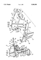
- FIG. 1 is a side elevational view of an outboard motor of the type embodying the present lower motor cover attachment
- FIG. 2 is an exploded top perspective view of the lower motor cover attachment of the present invention, with portions shown cut away for clarity.
- an outboard motor is shown and generally designated 10.
- the motor 10 is provided with a motor cowl 12 which includes an upper motor cover 14 and a lower motor cover 16, the lower motor cover being provided in two parts, a first cover portion 18 and a second cover portion 20 (best seen in FIG. 2).
- the first and second motor cover portions, 18, 20, are generally mirror images of each other and are configured to meet and partially enclose an internal combustion engine or power head 22 (shown hidden in FIG. 1).
- the cover portions 18, 20 are preferably injection molded of a thermoplastic material; however, other molding processes are contemplated, including but not limited to sheet molding or die cast aluminum.
- the material used for the cover portions 18, 20 is preferably a rigid plastic.
- An exhaust housing 24 depends from the engine 22 and is attached at a lower end 26 to a gear case housing 28.
- a propeller 30 is provided at a lower rear portion of the gear case housing 28 for propelling a boat through water, as is well known.
- a steering handle assembly 32 is located at a front end 34 of the motor 10.
- the steering handle assembly 32 includes a steering arm or bracket 36, a tiller handle 38, an axially rotatable throttle grip 40, and a gear shift lever 42.
- a stern bracket assembly 44 is provided with a vertical housing 46 including a shaft 48 axially disposed therein.
- a bracket 50 attached to the exhaust housing 24 surrounds the lower end of the housing 46.
- the shaft 48 engages the exhaust housing 24 at pivot point 52, and at an upper end, the shaft engages the steering arm 36.
- the stern bracket assembly 44 also includes at least one and preferably two threaded transom clamp members 54 for securing the bracket assembly 44 to the stern of a boat as is well known.
- the stern bracket assembly 44 permits the motor 10 to be pivotally controlled by the steering assembly 32 for steering purposes.
- the first cover portion 18 is provided with an overboard water indicator opening 68, through which is passed an overboard water indicator hose 70 (best seen in FIG. 1).
- Overboard indicator hose 70 is connected to the cooling system of the motor 10, and when the power head 22 is running, the hose emits a stream of water to indicate to the operator that the water pump is operating correctly to properly cool the engine.
- the indicator opening 68 is preferably located on the first cover portion 18, it is contemplated that, depending on the application, the opening could easily be located on the second cover portion 20.
- Each lower motor cover portion 18, 20 is also provided with a peripheral edge including a front edge portion 72 and a rear edge portion 74. Upon assembly of the lower motor cover 16 to the motor 10, the respective opposing rear edge portions 74 of the lower motor cover portions 18, 20 will be placed in contact with each other.
- the inner wall surfaces 62 of each lower motor cover portion 18, 20 are preferably provided with at least one laterally projecting formation 76 for engaging the exhaust housing 24, either directly, or indirectly through an intervening panel bracket (not shown).
- the opposing front edge portions 72 each engage a corresponding side of the intervening bracket.
- the lower motor cover 16 is also provided, on each lower motor cover portion 18, 20 with at least one attachment formation 78, which in the preferred embodiment is formed as opposed, coaxial pairs of integral bosses 80 having threaded bores 82.
- attachment formation 78 which in the preferred embodiment is formed as opposed, coaxial pairs of integral bosses 80 having threaded bores 82.
- Each boss 80 is configured to accept a threaded fastener, designated 84, which is inserted through a corresponding bore 82.
- the bores 82 may be internally threaded or in the preferred embodiment, are provided with captured threaded nuts (not shown).
- the fasteners 84 are screws having TORX heads, however, other types of fasteners 84 are contemplated including, but not limited to, machine screws and nuts.
- each of the lower motor cover portions 18, 20 is located a latch formation 86 configured for the attachment of a latch (not shown) for releasably securing the upper motor cover 14 to the lower motor cover 16.
- each rear end 66 is provided with a boss formation 88 dimensioned and configured to be coaxially opposed to a like formation on the opposing lower motor cover portion.
- a suitable fastener 84 such as a threaded fastener and nut combination is used to secure the boss formations 88 to each other.
- each lower motor cover portion 18, 20 is a mounting boss 90 which, along with the bosses 80F, are secured to the panel bracket (not shown) with threaded fasteners 84.
- the fastener 84 in the boss 80F is visible from the outside of the motor 10.
- the second motor cover portion 20 also may be provided with at least one access formation 92 to be used as an optional location for a fuel connection (not shown).
- the engagement of the threaded fasteners 84 in each of the bosses 80F, 80R, 88 and 90 is the mechanism for holding the lower motor cover portions 18, 20 to the motor 10.
- the lower motor cover portions 18, 20 may be removed from the motor 10 to provide access to the engine 22 or other internal components of the motor 10 for repair purposes.
- bosses 88 and 90 are located in a slightly recessed position on upper edges of the lower motor cover portions 18 and 20. Specifically, the bosses 88, 90 are located on, and form a portion of, an inner edge 94 of a shoulder 96 upon which rests the upper motor cover 14. Thus, the bosses 88, 90 are hidden when the upper motor cover 14 is in place. Upon removal of the upper motor cover 14, the bosses 88 and 90 are unobstructed and readily accessible. In fact, the bosses 88, 90 are accessible by an axially disposed tool such as a screwdriver (not shown) which was not possible in prior art lower motor cover attachments due to obscure locations of the mounting bosses.
- a screwdriver not shown
- the overboard water indicator opening 68 is disposed in a substantially coaxial position relative to the rear bosses 80R. In this manner, the corresponding fastener 84 is accessible by a screwdriver or appropriate tool inserted into the overboard water indicator opening 68. Naturally, the overboard water indicator hose 70 must be removed prior to removing the fastener. Also, the overboard water indicator opening 68 is dimensioned to accommodate the shaft of a screwdriver or appropriate tool (not shown).
- the upper motor cover 14 is first unlatched and removed from the motor 10.
- the overboard water indicator hose 70 is pulled from the overboard water indicator opening 68 from the inner wall surface 62 and through the now open upper end 98 of engine compartment 100 defined in part by the lower motor cover 16.
- a screwdriver or appropriate tool (not shown) is then inserted into the opening 68 and engages the fastener 84.
- the rear end 66 of the lower motor cover portions are detached from each other.
- removal of the fasteners 84 securing the bosses 80F and 90 releases the front end 64 of the lower motor cover portions 18, 20 from the motor 10.
- the present lower motor cover attachment features a more aesthetically pleasing outer configuration of the motor cover 14, 16.
- the present attachment facilitates maintenance of the power head 22 by simplifying the access to the lower motor cover attachment fasteners 84.
Abstract
Description
Claims (13)
Priority Applications (1)
| Application Number | Priority Date | Filing Date | Title |
|---|---|---|---|
| US08/065,993 US5360358A (en) | 1993-05-21 | 1993-05-21 | Hidden lower motor cover attachment means |
Applications Claiming Priority (1)
| Application Number | Priority Date | Filing Date | Title |
|---|---|---|---|
| US08/065,993 US5360358A (en) | 1993-05-21 | 1993-05-21 | Hidden lower motor cover attachment means |
Publications (1)
| Publication Number | Publication Date |
|---|---|
| US5360358A true US5360358A (en) | 1994-11-01 |
Family
ID=22066558
Family Applications (1)
| Application Number | Title | Priority Date | Filing Date |
|---|---|---|---|
| US08/065,993 Expired - Lifetime US5360358A (en) | 1993-05-21 | 1993-05-21 | Hidden lower motor cover attachment means |
Country Status (1)
| Country | Link |
|---|---|
| US (1) | US5360358A (en) |
Cited By (7)
| Publication number | Priority date | Publication date | Assignee | Title |
|---|---|---|---|---|
| US5921827A (en) * | 1996-12-19 | 1999-07-13 | Honda Giken Kogyo Kabushiki Kaisha | Outboard motor |
| US6527602B2 (en) * | 2000-01-17 | 2003-03-04 | Honda Giken Kogyo Kabushiki Kaisha | Outboard engine system |
| EP1382814A1 (en) * | 2002-07-18 | 2004-01-21 | Honda Giken Kogyo Kabushiki Kaisha | Outboard motor |
| US20040018785A1 (en) * | 2002-07-18 | 2004-01-29 | Toyoshi Yasuda | Cover joining structure for outboard engine unit |
| US20050079775A1 (en) * | 2003-03-31 | 2005-04-14 | Goichi Katayama | Outboard motor with cowling |
| US20070254539A1 (en) * | 2006-05-01 | 2007-11-01 | Honda Motor Co., Ltd. | Outboard engine unit |
| US10286990B2 (en) * | 2017-05-12 | 2019-05-14 | Yamaha Hatsudoki Kabushiki Kaisha | Outboard motor and sealing structure for divisible engine cover used therefor |
Citations (7)
| Publication number | Priority date | Publication date | Assignee | Title |
|---|---|---|---|---|
| US3933114A (en) * | 1973-08-06 | 1976-01-20 | Brunswick Corporation | Self-purging tell-tale nozzle |
| US4348194A (en) * | 1980-07-01 | 1982-09-07 | Brunswick Corporation | Cowl for an outboard motor |
| US4403972A (en) * | 1982-04-05 | 1983-09-13 | Outboard Marine Corporation | Marine propulsion device including engine housing pump mechanism |
| US4708673A (en) * | 1985-07-03 | 1987-11-24 | Outboard Marine Corporation | Outboard motor cowl assembly |
| US5055074A (en) * | 1990-05-18 | 1991-10-08 | Outboard Marine Corporation | Molded control panel for outboard motor |
| US5069643A (en) * | 1990-05-18 | 1991-12-03 | Outboard Marine Corporation | Molded lower motor cover |
| US5096208A (en) * | 1990-05-18 | 1992-03-17 | Outboard Marine Corporation | Motor cover seal |
-
1993
- 1993-05-21 US US08/065,993 patent/US5360358A/en not_active Expired - Lifetime
Patent Citations (7)
| Publication number | Priority date | Publication date | Assignee | Title |
|---|---|---|---|---|
| US3933114A (en) * | 1973-08-06 | 1976-01-20 | Brunswick Corporation | Self-purging tell-tale nozzle |
| US4348194A (en) * | 1980-07-01 | 1982-09-07 | Brunswick Corporation | Cowl for an outboard motor |
| US4403972A (en) * | 1982-04-05 | 1983-09-13 | Outboard Marine Corporation | Marine propulsion device including engine housing pump mechanism |
| US4708673A (en) * | 1985-07-03 | 1987-11-24 | Outboard Marine Corporation | Outboard motor cowl assembly |
| US5055074A (en) * | 1990-05-18 | 1991-10-08 | Outboard Marine Corporation | Molded control panel for outboard motor |
| US5069643A (en) * | 1990-05-18 | 1991-12-03 | Outboard Marine Corporation | Molded lower motor cover |
| US5096208A (en) * | 1990-05-18 | 1992-03-17 | Outboard Marine Corporation | Motor cover seal |
Cited By (12)
| Publication number | Priority date | Publication date | Assignee | Title |
|---|---|---|---|---|
| US5921827A (en) * | 1996-12-19 | 1999-07-13 | Honda Giken Kogyo Kabushiki Kaisha | Outboard motor |
| US6527602B2 (en) * | 2000-01-17 | 2003-03-04 | Honda Giken Kogyo Kabushiki Kaisha | Outboard engine system |
| EP1382814A1 (en) * | 2002-07-18 | 2004-01-21 | Honda Giken Kogyo Kabushiki Kaisha | Outboard motor |
| US20040014379A1 (en) * | 2002-07-18 | 2004-01-22 | Toyoshi Yasuda | Outboard motor |
| US20040018785A1 (en) * | 2002-07-18 | 2004-01-29 | Toyoshi Yasuda | Cover joining structure for outboard engine unit |
| US6846211B2 (en) * | 2002-07-18 | 2005-01-25 | Honda Giken Kogyo Kabushiki Kaisha | Cover joining structure for outboard engine unit |
| US6878022B2 (en) * | 2002-07-18 | 2005-04-12 | Honda Giken Kogyo Kabushiki Kaisha | Outboard motor |
| US20050079775A1 (en) * | 2003-03-31 | 2005-04-14 | Goichi Katayama | Outboard motor with cowling |
| US7118432B2 (en) * | 2003-03-31 | 2006-10-10 | Yamaha Marine Kabushiki Kaisha | Outboard motor with cowling |
| US20070254539A1 (en) * | 2006-05-01 | 2007-11-01 | Honda Motor Co., Ltd. | Outboard engine unit |
| US7621791B2 (en) * | 2006-05-01 | 2009-11-24 | Honda Motor Co., Ltd. | Outboard engine unit |
| US10286990B2 (en) * | 2017-05-12 | 2019-05-14 | Yamaha Hatsudoki Kabushiki Kaisha | Outboard motor and sealing structure for divisible engine cover used therefor |
Similar Documents
| Publication | Publication Date | Title |
|---|---|---|
| US5340343A (en) | Marine propulsion unit | |
| US4348194A (en) | Cowl for an outboard motor | |
| US7677938B2 (en) | Tiller arm | |
| US6840827B2 (en) | Outboard engine cowling | |
| US9073616B1 (en) | Marine engine cowling | |
| US5360358A (en) | Hidden lower motor cover attachment means | |
| US5069643A (en) | Molded lower motor cover | |
| US5803777A (en) | Latch for outboard motor protective cowling | |
| US5072704A (en) | Personal watercraft vehicle engine | |
| US4844031A (en) | Rotary latch mechanism for securing cowl sections of an outboard motor | |
| US6099371A (en) | Cowling for outboard motor | |
| US5460552A (en) | Adaptor plate mounting system for marine jet propulsion unit | |
| CA2131347C (en) | Jet pump mounting system | |
| US5350329A (en) | Flushing system for outboard motor | |
| US4867120A (en) | One piece lower skirt for improving water resistance of an outboard motor | |
| US6390865B1 (en) | Outboard motor | |
| US5055074A (en) | Molded control panel for outboard motor | |
| JPH1111389A (en) | Outboard motor | |
| CA1220674A (en) | Outboard motor mounting assembly | |
| JPH072180A (en) | Instrument for fixing lower motor cover of outboard motor | |
| US4763871A (en) | Mounting bracket for outboard motor | |
| US20020127927A1 (en) | Marine propulsion housing arrangement | |
| US7367855B2 (en) | Cable supporting structure for small boat | |
| US6790111B2 (en) | Outboard motor | |
| US5549492A (en) | Outboard motor |
Legal Events
| Date | Code | Title | Description |
|---|---|---|---|
| AS | Assignment |
Owner name: OUTBOARD MARINE CORPORATION, ILLINOIS Free format text: ASSIGNMENT OF ASSIGNORS INTEREST;ASSIGNOR:HAMAN, DAVID F.;REEL/FRAME:006561/0960 Effective date: 19930520 |
|
| STPP | Information on status: patent application and granting procedure in general |
Free format text: APPLICATION UNDERGOING PREEXAM PROCESSING |
|
| FPAY | Fee payment |
Year of fee payment: 4 |
|
| FPAY | Fee payment |
Year of fee payment: 8 |
|
| AS | Assignment |
Owner name: BOMBARDIER MOTOR CORPORATION OF AMERICA, FLORIDA Free format text: NUNC PRO TUNC ASSIGNMENT;ASSIGNOR:OUTBOARD MARINE CORPORATION;REEL/FRAME:014192/0583 Effective date: 20031211 |
|
| AS | Assignment |
Owner name: BOMBARDIER RECREATIONAL PRODUCTS INC., CANADA Free format text: ASSIGNMENT OF ASSIGNORS INTEREST;ASSIGNOR:BOMBARDIER MOTOR CORPORATION OF AMERICA;REEL/FRAME:014532/0362 Effective date: 20031218 |
|
| AS | Assignment |
Owner name: BRP US INC., WISCONSIN Free format text: ASSIGNMENT OF ASSIGNORS INTEREST;ASSIGNOR:BOMBARDIER RECREATIONAL PRODUCTS INC.;REEL/FRAME:016079/0257 Effective date: 20050131 |
|
| FPAY | Fee payment |
Year of fee payment: 12 |
|
| AS | Assignment |
Owner name: BANK OF MONTREAL, AS ADMINISTRATIVE AGENT, CANADA Free format text: SECURITY AGREEMENT;ASSIGNOR:BRP US INC.;REEL/FRAME:018350/0269 Effective date: 20060628 |
|
| FEPP | Fee payment procedure |
Free format text: PAYOR NUMBER ASSIGNED (ORIGINAL EVENT CODE: ASPN); ENTITY STATUS OF PATENT OWNER: LARGE ENTITY |