US5353699A - Harness producing apparatus and method - Google Patents

Harness producing apparatus and method Download PDF

Info

Publication number
US5353699A
US5353699A US08/151,002 US15100293A US5353699A US 5353699 A US5353699 A US 5353699A US 15100293 A US15100293 A US 15100293A US 5353699 A US5353699 A US 5353699A
Authority
US
United States
Prior art keywords
cable
marking
feeding
harness
path length
Prior art date
Legal status (The legal status is an assumption and is not a legal conclusion. Google has not performed a legal analysis and makes no representation as to the accuracy of the status listed.)
Expired - Fee Related
Application number
US08/151,002
Inventor
Yoshikazu Tamura
Current Assignee (The listed assignees may be inaccurate. Google has not performed a legal analysis and makes no representation or warranty as to the accuracy of the list.)
Sumitomo Wiring Systems Ltd
Original Assignee
Sumitomo Wiring Systems Ltd
Priority date (The priority date is an assumption and is not a legal conclusion. Google has not performed a legal analysis and makes no representation as to the accuracy of the date listed.)
Filing date
Publication date
Application filed by Sumitomo Wiring Systems Ltd filed Critical Sumitomo Wiring Systems Ltd
Assigned to SUMITOMO WIRING SYSTEMS, LTD. reassignment SUMITOMO WIRING SYSTEMS, LTD. ASSIGNMENT OF ASSIGNORS INTEREST (SEE DOCUMENT FOR DETAILS). Assignors: TAMURA, YOSHIKAZU
Application granted granted Critical
Publication of US5353699A publication Critical patent/US5353699A/en
Anticipated expiration legal-status Critical
Expired - Fee Related legal-status Critical Current

Links

Images

Classifications

    • HELECTRICITY
    • H01ELECTRIC ELEMENTS
    • H01RELECTRICALLY-CONDUCTIVE CONNECTIONS; STRUCTURAL ASSOCIATIONS OF A PLURALITY OF MUTUALLY-INSULATED ELECTRICAL CONNECTING ELEMENTS; COUPLING DEVICES; CURRENT COLLECTORS
    • H01R43/00Apparatus or processes specially adapted for manufacturing, assembling, maintaining, or repairing of line connectors or current collectors or for joining electric conductors
    • H01R43/28Apparatus or processes specially adapted for manufacturing, assembling, maintaining, or repairing of line connectors or current collectors or for joining electric conductors for wire processing before connecting to contact members, not provided for in groups H01R43/02 - H01R43/26
    • HELECTRICITY
    • H01ELECTRIC ELEMENTS
    • H01BCABLES; CONDUCTORS; INSULATORS; SELECTION OF MATERIALS FOR THEIR CONDUCTIVE, INSULATING OR DIELECTRIC PROPERTIES
    • H01B13/00Apparatus or processes specially adapted for manufacturing conductors or cables
    • H01B13/34Apparatus or processes specially adapted for manufacturing conductors or cables for marking conductors or cables
    • H01B13/345Apparatus or processes specially adapted for manufacturing conductors or cables for marking conductors or cables by spraying, ejecting or dispensing marking fluid
    • HELECTRICITY
    • H01ELECTRIC ELEMENTS
    • H01RELECTRICALLY-CONDUCTIVE CONNECTIONS; STRUCTURAL ASSOCIATIONS OF A PLURALITY OF MUTUALLY-INSULATED ELECTRICAL CONNECTING ELEMENTS; COUPLING DEVICES; CURRENT COLLECTORS
    • H01R43/00Apparatus or processes specially adapted for manufacturing, assembling, maintaining, or repairing of line connectors or current collectors or for joining electric conductors
    • H01R43/04Apparatus or processes specially adapted for manufacturing, assembling, maintaining, or repairing of line connectors or current collectors or for joining electric conductors for forming connections by deformation, e.g. crimping tool
    • H01R43/048Crimping apparatus or processes
    • H01R43/052Crimping apparatus or processes with wire-feeding mechanism
    • YGENERAL TAGGING OF NEW TECHNOLOGICAL DEVELOPMENTS; GENERAL TAGGING OF CROSS-SECTIONAL TECHNOLOGIES SPANNING OVER SEVERAL SECTIONS OF THE IPC; TECHNICAL SUBJECTS COVERED BY FORMER USPC CROSS-REFERENCE ART COLLECTIONS [XRACs] AND DIGESTS
    • Y10TECHNICAL SUBJECTS COVERED BY FORMER USPC
    • Y10TTECHNICAL SUBJECTS COVERED BY FORMER US CLASSIFICATION
    • Y10T29/00Metal working
    • Y10T29/49Method of mechanical manufacture
    • Y10T29/49002Electrical device making
    • Y10T29/49004Electrical device making including measuring or testing of device or component part
    • YGENERAL TAGGING OF NEW TECHNOLOGICAL DEVELOPMENTS; GENERAL TAGGING OF CROSS-SECTIONAL TECHNOLOGIES SPANNING OVER SEVERAL SECTIONS OF THE IPC; TECHNICAL SUBJECTS COVERED BY FORMER USPC CROSS-REFERENCE ART COLLECTIONS [XRACs] AND DIGESTS
    • Y10TECHNICAL SUBJECTS COVERED BY FORMER USPC
    • Y10TTECHNICAL SUBJECTS COVERED BY FORMER US CLASSIFICATION
    • Y10T29/00Metal working
    • Y10T29/49Method of mechanical manufacture
    • Y10T29/49002Electrical device making
    • Y10T29/49117Conductor or circuit manufacturing
    • Y10T29/49174Assembling terminal to elongated conductor
    • Y10T29/49181Assembling terminal to elongated conductor by deforming
    • YGENERAL TAGGING OF NEW TECHNOLOGICAL DEVELOPMENTS; GENERAL TAGGING OF CROSS-SECTIONAL TECHNOLOGIES SPANNING OVER SEVERAL SECTIONS OF THE IPC; TECHNICAL SUBJECTS COVERED BY FORMER USPC CROSS-REFERENCE ART COLLECTIONS [XRACs] AND DIGESTS
    • Y10TECHNICAL SUBJECTS COVERED BY FORMER USPC
    • Y10TTECHNICAL SUBJECTS COVERED BY FORMER US CLASSIFICATION
    • Y10T29/00Metal working
    • Y10T29/51Plural diverse manufacturing apparatus including means for metal shaping or assembling
    • Y10T29/5136Separate tool stations for selective or successive operation on work
    • Y10T29/5137Separate tool stations for selective or successive operation on work including assembling or disassembling station
    • Y10T29/5142Separate tool stations for selective or successive operation on work including assembling or disassembling station and means to sever work from supply

Definitions

  • This invention relates to an apparatus and a method of producing a harness in which a distinctive mark is applied to an outer periphery of an electrical cable.
  • harness there are many kinds of harness to be mounted on an automobile or the like. A distinctive mark is applied on an outer periphery of each electrical cable in order to easily distinguish a cable kind in each harness.
  • FIGS. 13 to 18 A prior apparatus for producing a harness on which the distinctive mark is applied will be described below by referring to FIGS. 13 to 18 for convenience of explanation.
  • FIG. 13 is a plan view of a prior harness producing apparatus.
  • FIG. 14 is a side view of the prior harness producing apparatus.
  • FIG. 15 is a side view of the prior harness producing apparatus illustrating another state.
  • FIG. 16 is a side view of the prior harness producing apparatus illustrating still another state.
  • FIGS. 13 to 16 A harness producing apparatus A1 disclosed in Japanese Patent Public Disclosure No. 80-151906 is illustrated in FIGS. 13 to 16.
  • the harness producing apparatus A1 comprises a cable feeding mechanism 20 having two feeding rollers 11, a pair of draw rollers 12a, a front side clamp 12, a cutter mechanism 13 having a plurality of cutters 13a and 13b, a rear side clamp 14, two terminal press-attaching mechanisms 21a and 21b disposed on the opposite sides of the cutter mechanism 13, and two marking mechanisms 22a and 22b disposed adjacent to the press-attaching mechanisms 21a and 21b.
  • An electrical cable 10 is passed along a predetermined cable pass line in the apparatus A1.
  • Both clamps 12 and 14 hold the cable 10 and the cutters 13a, 13b of the cutter mechanism 13 operates in synchronization with the clamps 12 and 14. Then, a middle cutter 13a in the cutter mechanism 13 cuts off the cable 10 and opposite side cutters 13b cut into sheaths of the cables. While maintaining this state, the front side clamp 12 moves in a direction shown by an arrow Q so that the cable 10 held by the clamp 12 (hereinafter referred to as "residual cable” 10) moves in the direction Q, thereby stripping the sheath from an end of the residual cable 10. At the same time, the rear side clamp 14 moves in a direction shown by an arrow P so that the cable 10 held by the clamp 14 (hereinafter referred to as "cut cable” 10) is stripped of its sheath at one end.
  • a terminal 2 (FIG. 1B) is press-attached to a stripped end of the residual cable 10 by a terminal press-attaching mechanism 21a, a distinctive mark is applied to the residual cable 10 near the stripped end thereof by the marking mechanism 22a, and the front side clamp 12 returns to its original position.
  • the cut cable 10 together with the rear side clamp 14 move in a direction shown by an arrow S in FIG. 1, a terminal (not shown) is press-attached to a stripped end of the cut cable 10 by a terminal press-attaching mechanism 21b, the distinctive mark is applied to the cut cable 10 near the stripped end thereof by the marking mechanism 22b, the cut cable 10 is discharged to a given discharging position, and the clamp 14 returns to the original position.
  • the indicative mark is applied to the cable simultaneously with a terminal press-attaching process, namely a cable end treating process after cutting the cable in the harness producing apparatus A1
  • Japanese Patent Public Disclosure No. 64-48319 (1989) discloses an apparatus which applies an indicative mark to an electrical cable prior to cutting it.
  • the marking mechanism 30 is disposed on an upstream from the cable feeding mechanism 20 in a cable Feeding direction P.
  • the marking mechanism 30 is provided with a pair of feeding rollers 31 adapted to clamp the cable 10 and a pair of marking heads 32 adapted to contact with the outer periphery of the cable 10.
  • a cable storage mechanism 40 is arranged between the cable feeding mechanism 20 and the marking mechanism 30 in order to receive the cable 10 therebetween.
  • the cable 10 is intermittently fed in the direction P by clamping and driving the cable 10 by the feeding rollers 31 in the marking mechanism 30.
  • the marking heads 32 press the cable during a feed resting period so that the distinctive mark 5 is applied to the cable 10 at a given outer face thereof.
  • the feeding rollers 11 of the cable feeding mechanism 20 feed the cable 10 intermittently in the same manner, the cutter mechanism 13 cut the cable 10, and the cable end treating processes such as end sheath stripping, terminal press-attaching and the like are carried out.
  • the apparatus A2 Since the distinctive mark is applied to the cable prior to cutting it in the harness producing apparatus A2, it is not necessary to dispose the marking mechanism 30 in the cable end treating section near the cutter mechanism 13 in which many elements are arranged complicatedly. Accordingly, the apparatus A2 does not bring about a problem of complication in construction.
  • a first object of the present invention is to provide a harness producing apparatus which has a simple construction and can apply a distinctive mark to a given area on a harness.
  • a second object of the present invention is to provide a harness producing method which can apply a distinctive mark to a given area on a harness.
  • the harness producing apparatus of the present invention comprises:
  • a cable feeding mechanism for intermittently feeding an electrical cable by a given length along its longitudinal direction; a marking mechanism disposed on an upper stream along a cable feeding direction of said cable feeding mechanism for applying a distinctive mark on said electrical cable during a feed resting period of said cable feeding mechanism; a cable end-treating unit disposed on a lower stream along said cable feeding direction of said cable feeding mechanism for cutting said cable fed by the given length to form a cut electrical cable having a given length during said feed resting period of said cable feeding mechanism; and a cable path length adjusting mechanism for adjusting a cable path length between said marking mechanism and said cable end treating mechanism in accordance with the length of said cut cable.
  • the harness producing method by using a harness producing apparatus of the present invention includes: a cable feeding mechanism for feeding an electrical cable in its longitudinal direction; a marking mechanism disposed on an upper stream along a cable feeding direction of said cable feeding mechanism for applying a distinctive mark on said electrical cable; a cable end treating unit disposed on a lower stream along said cable feeding direction of said cable feeding mechanism for cutting said cable fed; and a cable path length adjusting mechanism disposed between said marking mechanism and said cable end treating mechanism for adjustably setting a cable path length therebetween.
  • the method of the present invention comprises the steps of: setting said cable path length between said marking mechanism and said cable end treating unit to be a given length in accordance with the length of the cut cable by said cable path length adjusting mechanism; feeding said electrical cable intermittently by a given length by said cable feeding mechanism; applying a mark on said electrical cable during a feed resting period by said marking mechanism; and cutting said electrical cable fed by a given length from said cable feeding mechanism to form a cut electrical cable having a given length by said cable end treating unit during said feed resting period.
  • the cable path length adjusting mechanism for adjusting the cable path length is provided between the marking mechanism and the cable end treating mechanism, it is possible to position the electrical cable with respect to the cable end treating unit and marking mechanism only by feeding operation due to the cable feeding mechanism and by setting the cable path length to be a given length in accordance with the cut cable by means of the cable path length adjusting mechanism. At this time, a relative distance between the cable cutting position and the distinctive mark applying position is not changed. It is possible to apply the distinctive mark at the proper position on the cable and thus possible to precisely apply the distinctive mark on a given area on the harness.
  • the marking mechanism is disposed rather than near the cable end treating unit in which many devices are arranged, on an upper stream from the marking mechanism. Consequently, the marking mechanism does not bring a complication of construction into the apparatus.
  • FIG. 1 is a plan view of a first embodiment of a harness producing apparatus of the present invention
  • FIG. 2 is a side view of the first embodiment of the harness producing apparatus
  • FIG. 3 is a side view of the first embodiment of the harness producing apparatus illustrating another state
  • FIG. 4 is a side view of the first embodiment of the harness producing apparatus illustrating still another state
  • FIG. 5 is a side view of a main part of a marking mechanism to be applied to the first embodiment
  • FIG. 6 is a front side view of a main part of the marking mechanism to be applied to the first embodiment
  • FIG. 7 is a plan view of a harness produced by the first embodiment of the harness producing apparatus.
  • FIG. 8 is an explanatory view of setting a path length of an electrical cable in the first embodiment
  • FIG. 9 is a side view of a second embodiment of the harness producing apparatus of the present invention.
  • FIG. 10 is a plan view of a harness to which indicative marks are applied.
  • FIG. 11 is a front side view of another marking mechanism
  • FIG. 12 is a plan view of a harness in another form
  • FIG. 13 is a plan view of a prior harness producing apparatus
  • FIG. 14 is a side view of the prior harness producing apparatus
  • FIG. 15 is a side view of the prior harness producing apparatus illustrating another state.
  • FIG. 16 is a side view of the prior harness producing apparatus illustrating still another state.
  • FIGS. 1 to 4 a first embodiment of a harness producing apparatus H1 of the present invention will be explained below.
  • the harness producing apparatus comprises along an electrical cable pass line X a straightener 90, a marking mechanism 200, a cable path length adjusting mechanism 100, a cable feeding mechanism 110, a cable guide mechanism 120, a pair of draw rollers 131, a front side clamp 130, a cutter mechanism 140 and a rear side clamp 150, and terminal press-attaching mechanisms 160 and 170 arranged on opposite sides of the cutter mechanism 140.
  • An electrical cable 50 fed intermittently by the cable feeding mechanism 110 is passed in sequence through the straightener 90, marking mechanism 200, cable path length adjusting mechanism 100, cable feeding mechanism 110, cable guide mechanism 120, draw rollers 131 and front side clamp 130 so as to carry out a plurality of treatments described after. Consequently, a harness 51 having a distinctive mark 53 on a given area on the outer face and terminals 52 on the opposite ends shown in FIG. 7 is produced successively.
  • the cable feeding mechanism 110 has two rotatable Feeding rollers 111.
  • the feeding rollers 111 are rotated by a driving means not shown with the electrical cable 50 being wound about two feeding rollers 111 in an S like path, the cable 50 is fed by a distance corresponding to an amount of rotation of the rollers 111 in a longitudinal direction (cable pass line X) in the direction shown by an arrow P (hereinafter referred to as "cable feeding direction P").
  • the straightener 90 has a plurality of rollers 91 disposed on the opposite sides along the cable pass line X.
  • the cable 50 pulled from a stock reel not shown is corrected its residual curl nature when it passes through the rollers 91.
  • FIG. 5 is a side elevational view of a main part of the marking mechanism 200 and FIG. 6 is a front elevational view of the main part.
  • the marking mechanism 200 includes a clamp 210 which clamps and releases the cable 50 on the cable pass line X by driving means such as an air cylinder or the like and a pair of marking tools 220 disposed upper and lower sides along the cable pass line X.
  • Marking heads 221a and 221b made of a felt material are disposed on opposite sides of the marking tools 220.
  • the marking heads 221a and 221b are formed to be concave on their opposite faces so that the concaves accord a half outer peripheral face of the cable 50.
  • distances L4, L4 from a center position Y (FIG. 5) to each end of the marking heads 221a and 221b are the same as each other.
  • the distances L4. L4 are equal to distances L2.
  • L2 (FIG. 7) from an end of the cable of a harness described after to an end of a distinctive mark applying area.
  • the marking mechanism 200 is provided with a coloring agent supply means not shown, which supplies a coloring agent for marking the marking heads 221a and 221b at any time.
  • a driving means such as an &it cylinder or the like not shown moves tile pair of marking tools toward or away from each other so that the marking heads 221a and 221b clamp and release the cable 50 on tile cable pass line X.
  • the marking heads 221a and 221b contact with the outer peripheral face of the cable 50, the coloring agent is supplied on the outer peripheral face to present the distinctive mark 53 to the face.
  • the cable path length adjusting mechanism 100 has three rollers 101, 102, and 103 which are rotatably mounted on a body 105.
  • the center roller 102 out of the three rollers 101, 102, and 103 is supported so that it can move up and down and be fixed at any position by a securing means not shown.
  • the electrical cable 50 is passed beneath the opposite rollers 101 and 103 and above the center roller 102. It is possible to adjust the cable path length in the cable path length adjusting mechanism 100, namely between the marking mechanism 200 and the cable feeding mechanism 110 by displacing the fixed position of the center roller 102 up or down.
  • Two spaced guide rollers 121 and 122 are rotatably attached to an upper end of a body 125 of the cable guide mechanism 120. While the cable 50 fed from the feeding rollers 111 is loosened between the guide rollers 121 and 122, the cable 50 waits for driving until it is fed by draw rollers 131 described below.
  • a pair of draw rollers 131 can move toward and away from each other and serve to clamp the cable 50 on the cable pass line X so that the cable 50 is fed along the cable feeding direction P when the draw rollers 131 rotate.
  • the front side clamp 130 serves to clamp and release the cable 50 on the cable pass line X and can be moved in a horizontal plane including the cable pass line X by the driving means not shown.
  • the cutter mechanism 140 includes a pair of cutters 141 which cut off the cable 50 on the cable pass line X and two pairs of cutters 142 which are disposed on the opposite sides of the cutters 141 and cut into a sheath of the cable 50. Further, each pair of cutters 141 and 142 in the cutter mechanism 140 open and close in synchronization with each other.
  • the rear side clamp 150 serves to clamp and release the cable 50 on the cable pass line X and can be moved in a horizontal plane including the cable pass line X by the driving means not shown.
  • the cable end treating section is constituted of the front side clamp 130, cutter mechanism 140, rear side clamp 150, and terminal press-attaching mechanisms 160 and 170.
  • each of the driving means is connected to a control device not shown.
  • Each driving means is controlled in accordance with an output signal from the control device to carry out an operation described below.
  • the cable 50 pulled from a stock reel not shown is passed through a plurality of rollers 91 of the straightener 90 and then passed through the pair of marking tools 220 and the clamp 210. Further, the cable 50 moves on the lower side of the roller 101 and on the upper side of the roller 102 and on the lower side of the roller 103 and then is wound around the two feeding rollers 111 of the cable feeding mechanism 110 in an S like path. Further, after passing the cable 50 on two guide rollers 121 and 122 of the cable guide mechanism 120, the cable is passed through the pair of draw rollers 131, the front side clamp 130, the cutters 141 and 142 of the cutter mechanism 140 and the rear side clamp 150.
  • the clamp 210 of the marking mechanism 200 and the clamps 130 and 150 of the cable end treating section release the cable 50 respectively and the marking tools 220 are opened. Also, the pair of the draw rollers 131 are opened to release the cable 50.
  • cut cable 50 a sheath of the cable 50 held by the clamp 150 (hereinafter referred to as "cut cable” 50) is stripped from the cable in an upper stream in the cable feeding direction P (cutting and stripping process).
  • the marking tools 220 of the marking mechanism 200 are closed so that the marking heads 221a and 221b clamp the cable 50 and then the heads apply the coloring agent on the outer face of the cable 50 to present the distinctive mark 53 thereon.
  • the front side clamp 130 holding the residual cable 50 moves toward the terminal press-attaching mechanism 160 in the direction shown by the arrow R and the terminal 52 is press-attached on the stripped end of the residual cable 50 by the terminal-press-attaching mechanism 160. Then, tile front side clamp 130 moves in the direction S, so that the residual cable 50 is put on the cable pass line.
  • the rear side clamp 150 moves toward the terminal press-attaching mechanism 170 in the direction S, so that a terminal 52 is press-attached to the stripped end of the cut cable 50. Then, the rear side clamp 150 releases the cut cable 50 to discharge it at a given position and returns to the cable pass line X.
  • the clamp 210 of the marking mechanism 200 releases the cable 50
  • the feeding roller 111 of the cable feeding mechanism 110 is driven to feed the cable 50 by a distance corresponding to the cutting length L1 along the cable feeding direction P and the cable 50 is loosed between the guide rollers 121 and 122 of the cable guide mechanism 120 by a loop length corresponding to the cutting length L1.
  • the front side clamp 130 releases the cable 50 while the draw roller 131 clamps and drives the residual cable 50. Consequently, the cable 50 is fed toward the rear side clamp 150 until the loosed loop of the cable between the guide rollers 121 and 122 is eliminated.
  • the marking heads 221a and 221b of the marking mechanism can be positioned in opposition to a next distinctive mark area on the cable to be worked by feeding the cable 50 by the cutting length L1 by the feeding rollers 111.
  • the cable path length adjusting mechanism 100 which can set any cable path length is disposed between the cable feeding mechanism 110 and the marking mechanism 200 and the cable path length L3 from the cutting position PC1 for the harness 51 to the center position Y of the marking tools is set to be equal to the length L1 of the cut cable 51
  • the distances L3a and L3b arranging the cable 50 from the marking areas PC2a and PC2b of the marking heads 221a and 221b to the cutting position PC1 of the cutter 141 are equal to a sum (L1+L2) and a difference (L1-L2) of the cutting length L1 of the cable 50 and the distance L2 of tile marking area and also it is possible to position the cable 50 with respect to the cutter 141 and marking heads 221a and 221b by only a single mechanism, namely the cable feeding mechanism 110.
  • such feeding by only the cable feeding mechanism 110 does not change a relative position between the cable cutting position and the marking position and can properly apply the distinctive mark 53 to the marking area on the harness 51 with respect to the cable cutting position, even if a feeding amount is changed due to feeding errors in the cable feeding mechanism 110 in a long time lapse.
  • the marking mechanism 200 does not cause any problem of complication in the construction of the apparatus, since the marking mechanism 200 is not disposed in the cable end treating section around the cutter mechanism 140 in which so many elements are intricately arranged but disposed upstream from the cable feeding mechanism 110.
  • FIG. 9 is a schematic side elevational view of a second embodiment of a harness producing apparatus H2 of the present invention.
  • the harness producing apparatus comprises along an electrical cable pass line X a straightener 90, a marking mechanism 200, a cable feeding mechanism 110, a cable guide mechanism 120, a pair of draw rollers 131, a front side clamp 130, a cutter mechanism 140 and a rear side clamp 150, which are arranged along the cable pass line in the same manner as the first embodiment of the harness producing apparatus H1.
  • the straightener 90 and marking mechanism 200 are supported on a cable path length adjusting mechanism 300 so that they can be moved together with mechanism 300 along the cable pass line and fixed at any position by a securing means not shown.
  • the straightener 90 and marking mechanism 200 are moved relative to the cable feeding mechanism 110 by the cable path length adjusting mechanism 300, and a cable path length (L3) from the center position of the marking tools 220 to the cutting position of the cutter 141 is set to be equal to a cutting length (L1) of the cable 50, thereby producing the harness 51.
  • the relative position between the cutting position and the marking position can not be changed, thereby properly applying the distinctive mark 53 to the given marking area on the harness 51.
  • the kinds of the distinctive mark 53 and the distance L2 from the end of the harness 51 or the marking position are of the same at the opposite ends of the harness 51 in the above embodiments as shown in FIG. 7
  • the kinds of the distinctive marks 53 and 53' and the distances L2 and L2' from the end of the harness 51 to the marks 53 and 53' may be different from each other at the opposite ends thereof, as shown in FIG. 10.
  • tile right and left marking heads 221a and 221b are driven simultaneously by a single driving means in the marking mechanism 200 in the above embodiments, they may be individually driven by different driving means, as shown in FIG. 11. In this case,for example, only the right marking head 221a is driven so that it applies the mark 53 on the cable 50, thereby producing the harness 51 having the terminal 53 on one end and the stripped portion on the other end to be Jointed to another electrical cable, as shown in FIG. 12.
  • the present invention is not limited to the marking manner described in the above embodiments, in which the marking heads 221a and 221b made of a felt material which can hold the coloring agent contact with the outer surface of the cable 50 to provide the distinctive mark 53 on the cable.
  • a heat transcription system, an injection system or the like may be utilized.
  • the cable path length adjusting mechanism for adjusting the cable path length is provided between the marking mechanism and the cable end treating mechanism, it is possible to position the electrical cable with respect to the cable end treating unit and marking mechanism only by means of a feeding operation due to the cable feeding mechanism and by setting the cable path length to a given length in accordance with the cut cable by means of the cable path length adjusting mechanism. At this time, a relative distance between the cable cutting position and the distinctive mark applying position is not changed. It is possible to apply the distinctive mark at the proper position on the cable and thus is possible to precisely apply the distinctive mark at a given area on the harness.
  • the marking mechanism is disposed not near the cable end treating unit in which many devices have a complicated arrangement but on an upper stream from the marking mechanism. Consequently, the marking mechanism does not bring about a complicated construction of the apparatus.

Landscapes

  • Engineering & Computer Science (AREA)
  • Manufacturing & Machinery (AREA)
  • Manufacturing Of Electrical Connectors (AREA)
  • Insulated Conductors (AREA)
  • Processing Of Terminals (AREA)

Abstract

The invention aims to correctly apply a distinctive mark at a given position of a harness and simplify a construction of a harness producing apparatus. A cable path length adjusting mechanism 100 sets a cable path length from a cutting position of a cutter 141 to a center position of marking tools 220 to be the same as a length of an electrical cable 50 to be cut. A cable feeding mechanism 110 locates the cable 50 with respect to the cutter 141 and marking head 221a and 221b only by a feed of the cable. It is possible to correctly apply the distinctive mark on a given area of the harness without changing a relative distance between the cutting position of the cable 50 and the applying position of the distinctive mark. Further, a marking mechanism 200 is disposed on an upper stream with respect to the cable feeding mechanism 110 and is not disposed in the cable end treating unit in which devices are complicatedly arranged, thereby simplifying the construction of the apparatus.

Description

BACKGROUND OF THE INVENTION
1. Field of the Invention
This invention relates to an apparatus and a method of producing a harness in which a distinctive mark is applied to an outer periphery of an electrical cable.
2. Statement of the Prior Art
There are many kinds of harness to be mounted on an automobile or the like. A distinctive mark is applied on an outer periphery of each electrical cable in order to easily distinguish a cable kind in each harness.
A prior apparatus for producing a harness on which the distinctive mark is applied will be described below by referring to FIGS. 13 to 18 for convenience of explanation.
FIG. 13 is a plan view of a prior harness producing apparatus. FIG. 14 is a side view of the prior harness producing apparatus. FIG. 15 is a side view of the prior harness producing apparatus illustrating another state. FIG. 16 is a side view of the prior harness producing apparatus illustrating still another state.
A harness producing apparatus A1 disclosed in Japanese Patent Public Disclosure No. 80-151906 is illustrated in FIGS. 13 to 16.
The harness producing apparatus A1 comprises a cable feeding mechanism 20 having two feeding rollers 11, a pair of draw rollers 12a, a front side clamp 12, a cutter mechanism 13 having a plurality of cutters 13a and 13b, a rear side clamp 14, two terminal press- attaching mechanisms 21a and 21b disposed on the opposite sides of the cutter mechanism 13, and two marking mechanisms 22a and 22b disposed adjacent to the press- attaching mechanisms 21a and 21b. An electrical cable 10 is passed along a predetermined cable pass line in the apparatus A1.
Both clamps 12 and 14 hold the cable 10 and the cutters 13a, 13b of the cutter mechanism 13 operates in synchronization with the clamps 12 and 14. Then, a middle cutter 13a in the cutter mechanism 13 cuts off the cable 10 and opposite side cutters 13b cut into sheaths of the cables. While maintaining this state, the front side clamp 12 moves in a direction shown by an arrow Q so that the cable 10 held by the clamp 12 (hereinafter referred to as "residual cable" 10) moves in the direction Q, thereby stripping the sheath from an end of the residual cable 10. At the same time, the rear side clamp 14 moves in a direction shown by an arrow P so that the cable 10 held by the clamp 14 (hereinafter referred to as "cut cable" 10) is stripped of its sheath at one end.
Then, The residual cable 10 together with the front side clamp 12 move in a direction shown by an arrow R in FIG. 13, a terminal 2 (FIG. 1B) is press-attached to a stripped end of the residual cable 10 by a terminal press-attaching mechanism 21a, a distinctive mark is applied to the residual cable 10 near the stripped end thereof by the marking mechanism 22a, and the front side clamp 12 returns to its original position.
On the other hand, the cut cable 10 together with the rear side clamp 14 move in a direction shown by an arrow S in FIG. 1, a terminal (not shown) is press-attached to a stripped end of the cut cable 10 by a terminal press-attaching mechanism 21b, the distinctive mark is applied to the cut cable 10 near the stripped end thereof by the marking mechanism 22b, the cut cable 10 is discharged to a given discharging position, and the clamp 14 returns to the original position.
Then, after both clamps 12 and 14 release the cable, two feeding rollers 11 are rotated and the electrical cable 10 is fed toward the draw rollers 12a. At a little time lag after feeding the cable, the draw rollers rotate so that the sheathed cable 10 is fed to the rear side clamp 14.
Thereafter, the above steps are repeated to produce the cut cable (harness) which is provided with the terminals 2 on the opposite stripped ends thereof and the distinctive mark on the given area.
However, since the indicative mark is applied to the cable simultaneously with a terminal press-attaching process, namely a cable end treating process after cutting the cable in the harness producing apparatus A1, it is necessary to further dispose the marking mechanisms 22a and 22b on a cable end treating section on which the front side clamp 12, cutter mechanism 13, rear side clamp 14, terminal press- attaching mechanisms 21a and 21b and the like have a complicated arrangement, thus making the construction intricate.
In order to eliminate the above problem, Japanese Patent Public Disclosure No. 64-48319 (1989) discloses an apparatus which applies an indicative mark to an electrical cable prior to cutting it.
In another prior harness producing apparatus A2 shown in FIG. 16, the marking mechanism 30 is disposed on an upstream from the cable feeding mechanism 20 in a cable Feeding direction P. The marking mechanism 30 is provided with a pair of feeding rollers 31 adapted to clamp the cable 10 and a pair of marking heads 32 adapted to contact with the outer periphery of the cable 10. Further, a cable storage mechanism 40 is arranged between the cable feeding mechanism 20 and the marking mechanism 30 in order to receive the cable 10 therebetween.
In the harness producing apparatus A2, the cable 10 is intermittently fed in the direction P by clamping and driving the cable 10 by the feeding rollers 31 in the marking mechanism 30. The marking heads 32 press the cable during a feed resting period so that the distinctive mark 5 is applied to the cable 10 at a given outer face thereof.
On the other hand, the feeding rollers 11 of the cable feeding mechanism 20 feed the cable 10 intermittently in the same manner, the cutter mechanism 13 cut the cable 10, and the cable end treating processes such as end sheath stripping, terminal press-attaching and the like are carried out.
Since the distinctive mark is applied to the cable prior to cutting it in the harness producing apparatus A2, it is not necessary to dispose the marking mechanism 30 in the cable end treating section near the cutter mechanism 13 in which many elements are arranged complicatedly. Accordingly, the apparatus A2 does not bring about a problem of complication in construction.
However, since the feeding rollers 31 of the marking mechanism 30 feed the cable intermittently in the apparatus A2 while the feeding rollers 11 of the cable feeding mechanism 20 feed the cable intermittently independent upon the feeding rollers 31, a gap between a cutting position of the cable 10 and a marking position of the cable is caused due to feed errors between both rollers 11 and 31 upon operation of the apparatus for a long time. Consequently, it is impossible to precisely apply the distinctive mark to a given area on the harness 1.
SUMMARY OF THE INVENTION
A first object of the present invention is to provide a harness producing apparatus which has a simple construction and can apply a distinctive mark to a given area on a harness.
A second object of the present invention is to provide a harness producing method which can apply a distinctive mark to a given area on a harness.
In order to achieve the first object, the harness producing apparatus of the present invention comprises:
a cable feeding mechanism for intermittently feeding an electrical cable by a given length along its longitudinal direction; a marking mechanism disposed on an upper stream along a cable feeding direction of said cable feeding mechanism for applying a distinctive mark on said electrical cable during a feed resting period of said cable feeding mechanism; a cable end-treating unit disposed on a lower stream along said cable feeding direction of said cable feeding mechanism for cutting said cable fed by the given length to form a cut electrical cable having a given length during said feed resting period of said cable feeding mechanism; and a cable path length adjusting mechanism for adjusting a cable path length between said marking mechanism and said cable end treating mechanism in accordance with the length of said cut cable.
In order to achieve the second object, the harness producing method by using a harness producing apparatus of the present invention includes: a cable feeding mechanism for feeding an electrical cable in its longitudinal direction; a marking mechanism disposed on an upper stream along a cable feeding direction of said cable feeding mechanism for applying a distinctive mark on said electrical cable; a cable end treating unit disposed on a lower stream along said cable feeding direction of said cable feeding mechanism for cutting said cable fed; and a cable path length adjusting mechanism disposed between said marking mechanism and said cable end treating mechanism for adjustably setting a cable path length therebetween. The method of the present invention comprises the steps of: setting said cable path length between said marking mechanism and said cable end treating unit to be a given length in accordance with the length of the cut cable by said cable path length adjusting mechanism; feeding said electrical cable intermittently by a given length by said cable feeding mechanism; applying a mark on said electrical cable during a feed resting period by said marking mechanism; and cutting said electrical cable fed by a given length from said cable feeding mechanism to form a cut electrical cable having a given length by said cable end treating unit during said feed resting period.
According to the present invention, since the cable path length adjusting mechanism for adjusting the cable path length is provided between the marking mechanism and the cable end treating mechanism, it is possible to position the electrical cable with respect to the cable end treating unit and marking mechanism only by feeding operation due to the cable feeding mechanism and by setting the cable path length to be a given length in accordance with the cut cable by means of the cable path length adjusting mechanism. At this time, a relative distance between the cable cutting position and the distinctive mark applying position is not changed. It is possible to apply the distinctive mark at the proper position on the cable and thus possible to precisely apply the distinctive mark on a given area on the harness. In addition, the marking mechanism is disposed rather than near the cable end treating unit in which many devices are arranged, on an upper stream from the marking mechanism. Consequently, the marking mechanism does not bring a complication of construction into the apparatus.
BRIEF DESCRIPTION OF THE DRAWINGS
FIG. 1 is a plan view of a first embodiment of a harness producing apparatus of the present invention;
FIG. 2 is a side view of the first embodiment of the harness producing apparatus;
FIG. 3 is a side view of the first embodiment of the harness producing apparatus illustrating another state;
FIG. 4 is a side view of the first embodiment of the harness producing apparatus illustrating still another state;
FIG. 5 is a side view of a main part of a marking mechanism to be applied to the first embodiment;
FIG. 6 is a front side view of a main part of the marking mechanism to be applied to the first embodiment;
FIG. 7 is a plan view of a harness produced by the first embodiment of the harness producing apparatus;
FIG. 8 is an explanatory view of setting a path length of an electrical cable in the first embodiment;
FIG. 9 is a side view of a second embodiment of the harness producing apparatus of the present invention;
FIG. 10 is a plan view of a harness to which indicative marks are applied;
FIG. 11 is a front side view of another marking mechanism;
FIG. 12 is a plan view of a harness in another form;
FIG. 13 is a plan view of a prior harness producing apparatus;
FIG. 14 is a side view of the prior harness producing apparatus;
FIG. 15 is a side view of the prior harness producing apparatus illustrating another state; and
FIG. 16 is a side view of the prior harness producing apparatus illustrating still another state.
DETAILED DESCRIPTION OF THE PREFERRED EMBODIMENTS
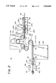
Referring now to FIGS. 1 to 4, a first embodiment of a harness producing apparatus H1 of the present invention will be explained below.
As shown in the drawings, the harness producing apparatus comprises along an electrical cable pass line X a straightener 90, a marking mechanism 200, a cable path length adjusting mechanism 100, a cable feeding mechanism 110, a cable guide mechanism 120, a pair of draw rollers 131, a front side clamp 130, a cutter mechanism 140 and a rear side clamp 150, and terminal press-attaching mechanisms 160 and 170 arranged on opposite sides of the cutter mechanism 140. An electrical cable 50 fed intermittently by the cable feeding mechanism 110 is passed in sequence through the straightener 90, marking mechanism 200, cable path length adjusting mechanism 100, cable feeding mechanism 110, cable guide mechanism 120, draw rollers 131 and front side clamp 130 so as to carry out a plurality of treatments described after. Consequently, a harness 51 having a distinctive mark 53 on a given area on the outer face and terminals 52 on the opposite ends shown in FIG. 7 is produced successively.
The cable feeding mechanism 110 has two rotatable Feeding rollers 111. When the feeding rollers 111 are rotated by a driving means not shown with the electrical cable 50 being wound about two feeding rollers 111 in an S like path, the cable 50 is fed by a distance corresponding to an amount of rotation of the rollers 111 in a longitudinal direction (cable pass line X) in the direction shown by an arrow P (hereinafter referred to as "cable feeding direction P").
The straightener 90 has a plurality of rollers 91 disposed on the opposite sides along the cable pass line X. The cable 50 pulled from a stock reel not shown is corrected its residual curl nature when it passes through the rollers 91.
FIG. 5 is a side elevational view of a main part of the marking mechanism 200 and FIG. 6 is a front elevational view of the main part. As shown in FIGS. 1 to 6, the marking mechanism 200 includes a clamp 210 which clamps and releases the cable 50 on the cable pass line X by driving means such as an air cylinder or the like and a pair of marking tools 220 disposed upper and lower sides along the cable pass line X.
Marking heads 221a and 221b made of a felt material are disposed on opposite sides of the marking tools 220. The marking heads 221a and 221b are formed to be concave on their opposite faces so that the concaves accord a half outer peripheral face of the cable 50. Also, in the marking tools 220, distances L4, L4 from a center position Y (FIG. 5) to each end of the marking heads 221a and 221b are the same as each other. The distances L4. L4 are equal to distances L2. L2 (FIG. 7) from an end of the cable of a harness described after to an end of a distinctive mark applying area. Further, the marking mechanism 200 is provided with a coloring agent supply means not shown, which supplies a coloring agent for marking the marking heads 221a and 221b at any time.
A driving means such as an &it cylinder or the like not shown moves tile pair of marking tools toward or away from each other so that the marking heads 221a and 221b clamp and release the cable 50 on tile cable pass line X. When the marking heads 221a and 221b contact with the outer peripheral face of the cable 50, the coloring agent is supplied on the outer peripheral face to present the distinctive mark 53 to the face.
The cable path length adjusting mechanism 100 has three rollers 101, 102, and 103 which are rotatably mounted on a body 105. The center roller 102 out of the three rollers 101, 102, and 103 is supported so that it can move up and down and be fixed at any position by a securing means not shown.
The electrical cable 50 is passed beneath the opposite rollers 101 and 103 and above the center roller 102. It is possible to adjust the cable path length in the cable path length adjusting mechanism 100, namely between the marking mechanism 200 and the cable feeding mechanism 110 by displacing the fixed position of the center roller 102 up or down.
Two spaced guide rollers 121 and 122 are rotatably attached to an upper end of a body 125 of the cable guide mechanism 120. While the cable 50 fed from the feeding rollers 111 is loosened between the guide rollers 121 and 122, the cable 50 waits for driving until it is fed by draw rollers 131 described below.
A pair of draw rollers 131 can move toward and away from each other and serve to clamp the cable 50 on the cable pass line X so that the cable 50 is fed along the cable feeding direction P when the draw rollers 131 rotate.
The front side clamp 130 serves to clamp and release the cable 50 on the cable pass line X and can be moved in a horizontal plane including the cable pass line X by the driving means not shown.
The cutter mechanism 140 includes a pair of cutters 141 which cut off the cable 50 on the cable pass line X and two pairs of cutters 142 which are disposed on the opposite sides of the cutters 141 and cut into a sheath of the cable 50. Further, each pair of cutters 141 and 142 in the cutter mechanism 140 open and close in synchronization with each other.
The rear side clamp 150 serves to clamp and release the cable 50 on the cable pass line X and can be moved in a horizontal plane including the cable pass line X by the driving means not shown.
The cable end treating section is constituted of the front side clamp 130, cutter mechanism 140, rear side clamp 150, and terminal press-attaching mechanisms 160 and 170.
On the other hand, in a harness producing apparatus H1, each of the driving means is connected to a control device not shown. Each driving means is controlled in accordance with an output signal from the control device to carry out an operation described below.
The operation of the harness producing apparatus H1 is described below.
In the case of setting the electrical cable 50 in the apparatus prior to starting the operation, the cable 50 pulled from a stock reel not shown is passed through a plurality of rollers 91 of the straightener 90 and then passed through the pair of marking tools 220 and the clamp 210. Further, the cable 50 moves on the lower side of the roller 101 and on the upper side of the roller 102 and on the lower side of the roller 103 and then is wound around the two feeding rollers 111 of the cable feeding mechanism 110 in an S like path. Further, after passing the cable 50 on two guide rollers 121 and 122 of the cable guide mechanism 120, the cable is passed through the pair of draw rollers 131, the front side clamp 130, the cutters 141 and 142 of the cutter mechanism 140 and the rear side clamp 150.
At this time, the clamp 210 of the marking mechanism 200 and the clamps 130 and 150 of the cable end treating section release the cable 50 respectively and the marking tools 220 are opened. Also, the pair of the draw rollers 131 are opened to release the cable 50.
The fixed position of the roller 102 of the cable path length adjusting mechanism 100 is set to be L3=L1, when L1 is a length (cutting length) of an electrical cable of the harness 51 to be produced and L3 is a distance (cable path length) from a cutting position PC1 of the harness to the center position Y of the marking tools 220 along the cable pass line X, as shown in FIGS. 7 and 8.
When L2 is a distance (hereinafter referred to as "distinctive mark area distance") from a cable end of the harness 51 to an area end of the distinctive mark 53 and L3a and L3b (FIG. 1) is a distance (cable pass distance) from ends PC2a and PC2b of the distinctive mark area (hereinafter referred to as "distinctive mark area") worked by the marking heads 221a and 221b to the cutting position PC1 worked by the cutter 141 along the table pass line X, since the size relation L4=L2 is satisfied, the above equation L3=L1 may be expressed by equations L3a=L1+L2 and L3b=L1-L2.
When a command for starting the operation is given to the above apparatus in this state, after the cable 50 is held by the front and rear side clamps 130 and 150, and the clamp 210 of the marking mechanism 200, the cutters 141 and 142 are closed in synchronization with each other so that the cutter 141 cuts off the cable and the cutters 142 cut into the sheath on the cable on the opposite sides of the cutting position. Further, the front side clamp 130 moves in a direction Q opposite to the cable feeding direction P, so that a sheath of the cable 50 held by the clamp 130 (hereinafter referred to as "residual cable 50") is stripped from the cable in a lower stream in the cable feeding direction P. In parallel with this process, the rear side clamp 150 moves in the cable feeding direction P, so that a sheath of the cable 50 held by the clamp 150 (hereinafter referred to as "cut cable" 50) is stripped from the cable in an upper stream in the cable feeding direction P (cutting and stripping process).
On the other hand, in synchronization with these cutting and stripping processes, the marking tools 220 of the marking mechanism 200 are closed so that the marking heads 221a and 221b clamp the cable 50 and then the heads apply the coloring agent on the outer face of the cable 50 to present the distinctive mark 53 thereon.
The front side clamp 130 holding the residual cable 50 moves toward the terminal press-attaching mechanism 160 in the direction shown by the arrow R and the terminal 52 is press-attached on the stripped end of the residual cable 50 by the terminal-press-attaching mechanism 160. Then, tile front side clamp 130 moves in the direction S, so that the residual cable 50 is put on the cable pass line. In parallel with this process, the rear side clamp 150 moves toward the terminal press-attaching mechanism 170 in the direction S, so that a terminal 52 is press-attached to the stripped end of the cut cable 50. Then, the rear side clamp 150 releases the cut cable 50 to discharge it at a given position and returns to the cable pass line X.
While the terminal press-attaching process is being curried out, the clamp 210 of the marking mechanism 200 releases the cable 50, the feeding roller 111 of the cable feeding mechanism 110 is driven to feed the cable 50 by a distance corresponding to the cutting length L1 along the cable feeding direction P and the cable 50 is loosed between the guide rollers 121 and 122 of the cable guide mechanism 120 by a loop length corresponding to the cutting length L1.
The front side clamp 130 releases the cable 50 while the draw roller 131 clamps and drives the residual cable 50. Consequently, the cable 50 is fed toward the rear side clamp 150 until the loosed loop of the cable between the guide rollers 121 and 122 is eliminated. Thus, the marking heads 221a and 221b of the marking mechanism can be positioned in opposition to a next distinctive mark area on the cable to be worked by feeding the cable 50 by the cutting length L1 by the feeding rollers 111.
Hereafter, the above operation is repeated, thereby producing the harness 51 having the distinctive mark 53 on the given area on the outer face and terminals 52 on the opposite ends.
According to the harness producing apparatus H1, since the cable path length adjusting mechanism 100 which can set any cable path length is disposed between the cable feeding mechanism 110 and the marking mechanism 200 and the cable path length L3 from the cutting position PC1 for the harness 51 to the center position Y of the marking tools is set to be equal to the length L1 of the cut cable 51, the distances L3a and L3b arranging the cable 50 from the marking areas PC2a and PC2b of the marking heads 221a and 221b to the cutting position PC1 of the cutter 141 are equal to a sum (L1+L2) and a difference (L1-L2) of the cutting length L1 of the cable 50 and the distance L2 of tile marking area and also it is possible to position the cable 50 with respect to the cutter 141 and marking heads 221a and 221b by only a single mechanism, namely the cable feeding mechanism 110. Accordingly, such feeding by only the cable feeding mechanism 110 does not change a relative position between the cable cutting position and the marking position and can properly apply the distinctive mark 53 to the marking area on the harness 51 with respect to the cable cutting position, even if a feeding amount is changed due to feeding errors in the cable feeding mechanism 110 in a long time lapse.
Also, the marking mechanism 200 does not cause any problem of complication in the construction of the apparatus, since the marking mechanism 200 is not disposed in the cable end treating section around the cutter mechanism 140 in which so many elements are intricately arranged but disposed upstream from the cable feeding mechanism 110.
FIG. 9 is a schematic side elevational view of a second embodiment of a harness producing apparatus H2 of the present invention. As shown in the drawing, the harness producing apparatus comprises along an electrical cable pass line X a straightener 90, a marking mechanism 200, a cable feeding mechanism 110, a cable guide mechanism 120, a pair of draw rollers 131, a front side clamp 130, a cutter mechanism 140 and a rear side clamp 150, which are arranged along the cable pass line in the same manner as the first embodiment of the harness producing apparatus H1.
The straightener 90 and marking mechanism 200 are supported on a cable path length adjusting mechanism 300 so that they can be moved together with mechanism 300 along the cable pass line and fixed at any position by a securing means not shown.
The other constructions of the second embodiment H2 are the same as those of the first embodiment H1.
In the harness producing apparatus H2, the straightener 90 and marking mechanism 200 are moved relative to the cable feeding mechanism 110 by the cable path length adjusting mechanism 300, and a cable path length (L3) from the center position of the marking tools 220 to the cutting position of the cutter 141 is set to be equal to a cutting length (L1) of the cable 50, thereby producing the harness 51.
In the harness producing apparatus H2, since the positioning of the cable 50 with respect to the cutting position for the cutter 141 and the marking position for the marking heads 221a and 221b can be carried out by only the cable feeding mechanism 110, the relative position between the cutting position and the marking position can not be changed, thereby properly applying the distinctive mark 53 to the given marking area on the harness 51.
It is also possible to apply the distinctive mark 53 to any marking area on the harness 51 by suitably altering a length (L4) of the marking tools 220 along the cable feeding direction P.
Although the kind of the distinctive mark 53 and the distance L2 from the end of the harness 51 or the marking position are of the same at the opposite ends of the harness 51 in the above embodiments as shown in FIG. 7, the kinds of the distinctive marks 53 and 53' and the distances L2 and L2' from the end of the harness 51 to the marks 53 and 53' may be different from each other at the opposite ends thereof, as shown in FIG. 10. In this case, the right and left marking heads 221a and 221b may be formed in accordance with the right and left distinctive marks 53' and 53 and the respective distances L3, L3a and L3b shown in FIG. 8 may be set to be L3=L1, L3a=L1+L2, and L3b=L1-L2'.
Also, although tile right and left marking heads 221a and 221b are driven simultaneously by a single driving means in the marking mechanism 200 in the above embodiments, they may be individually driven by different driving means, as shown in FIG. 11. In this case,for example, only the right marking head 221a is driven so that it applies the mark 53 on the cable 50, thereby producing the harness 51 having the terminal 53 on one end and the stripped portion on the other end to be Jointed to another electrical cable, as shown in FIG. 12.
It should be noted that the present invention is not limited to the marking manner described in the above embodiments, in which the marking heads 221a and 221b made of a felt material which can hold the coloring agent contact with the outer surface of the cable 50 to provide the distinctive mark 53 on the cable. For example, a heat transcription system, an injection system or the like may be utilized.
According to the present invention, since the cable path length adjusting mechanism for adjusting the cable path length is provided between the marking mechanism and the cable end treating mechanism, it is possible to position the electrical cable with respect to the cable end treating unit and marking mechanism only by means of a feeding operation due to the cable feeding mechanism and by setting the cable path length to a given length in accordance with the cut cable by means of the cable path length adjusting mechanism. At this time, a relative distance between the cable cutting position and the distinctive mark applying position is not changed. It is possible to apply the distinctive mark at the proper position on the cable and thus is possible to precisely apply the distinctive mark at a given area on the harness. In addition, the marking mechanism is disposed not near the cable end treating unit in which many devices have a complicated arrangement but on an upper stream from the marking mechanism. Consequently, the marking mechanism does not bring about a complicated construction of the apparatus.

Claims (2)

What is claimed is:
1. A harness producing apparatus comprising:
a cable feeding mechanism for intermittently feeding an electrical cable by a given length in its longitudinal direction;
a marking mechanism disposed on an upper stream along a cable feeding direction of said cable feeding mechanism for applying a distinctive mark on said electrical cable during a feed resting period of said cable feeding mechanism;
a cable end treating unit disposed on a lower stream in said cable feeding direction of said cable feeding mechanism for cutting said cable fed by the given length to form a cut electrical cable having a given length during said feed resting period of said cable feeding mechanism; and
a cable path length adjusting mechanism for adjusting a cable path length between said marking mechanism and said cable end treating mechanism in accordance with the length of said cut cable.
2. A harness producing method by using a harness producing apparatus including:
a cable feeding mechanism for feeding an electrical cable in its longitudinal direction;
a marking mechanism disposed on an upper stream along a cable feeding direction of said cable feeding mechanism for applying a distinctive mark on said electrical cable;
a cable end treating unit disposed on a lower stream in said cable feeding direction of said cable feeding mechanism for cutting said cable fed; and
a cable path length adjusting mechanism disposed between said marking mechanism and said cable end treating mechanism for adjustably setting a cable path length therebetween;
said method comprising the steps of:
setting said cable path length between said marking mechanism and said cable end treating unit to be a given length in accordance with the length of the cut cable by said cable path adjusting mechanism:
feeding said electrical cable intermittently by a given length by said cable feeding mechanism;
applying a distinctive mark on said electrical cable during a feed resting period by said marking mechanism; and
cutting said electrical cable fed by a given length from said cable feeding mechanism to form a cut electrical cable having a given length by said cable end treating unit during said feed resting period.
US08/151,002 1992-11-13 1993-11-12 Harness producing apparatus and method Expired - Fee Related US5353699A (en)

Applications Claiming Priority (2)

Application Number Priority Date Filing Date Title
JP4-328829 1992-11-13
JP4328829A JP2827771B2 (en) 1992-11-13 1992-11-13 Harness manufacturing apparatus and method of using the same

Publications (1)

Publication Number Publication Date
US5353699A true US5353699A (en) 1994-10-11

Family

ID=18214553

Family Applications (1)

Application Number Title Priority Date Filing Date
US08/151,002 Expired - Fee Related US5353699A (en) 1992-11-13 1993-11-12 Harness producing apparatus and method

Country Status (3)

Country Link
US (1) US5353699A (en)
JP (1) JP2827771B2 (en)
GB (1) GB2272655B (en)

Cited By (9)

* Cited by examiner, † Cited by third party
Publication number Priority date Publication date Assignee Title
DE19516490A1 (en) * 1995-05-05 1996-11-21 Mosebach Gmbh Manipulation process for automatic fitting of contacts to cable
US5806171A (en) * 1995-05-26 1998-09-15 Johnson Electric S.A. Method and apparatus for polymeric type positive temperature coefficient thermistors
US6484628B2 (en) * 2000-05-31 2002-11-26 Sumitomo Wiring Systems, Ltd. Wire printing method and apparatus
WO2003019580A1 (en) * 2001-08-27 2003-03-06 Yazaki Corporation Method and device for manufacturing wire harness
US20040063359A1 (en) * 2002-07-25 2004-04-01 Toshiyuki Hosokawa Process for mounting parts to cable
US20050134674A1 (en) * 2002-02-28 2005-06-23 Takahisa Misawa Tube thermal transfer printer machine
CN1813319B (en) * 2003-05-30 2011-09-07 矢崎总业株式会社 Wire harness assembling method and wire harness
US20120145072A1 (en) * 2005-12-09 2012-06-14 Yazaki Corporation Wire coloring apparatus incluidng a roller
US20180174715A1 (en) * 2016-12-15 2018-06-21 The Boeing Company Automated wire processing system and methods

Families Citing this family (10)

* Cited by examiner, † Cited by third party
Publication number Priority date Publication date Assignee Title
ES2113801B1 (en) * 1994-11-21 1999-01-01 Mecanismos Aux Ind LINE CUTTING AND STRIPPING MACHINE AND ITS OPERATING PROCEDURE.
MXPA04006374A (en) * 2001-12-28 2004-11-10 Yazaki Corp Method for order receipt production of electric wire and its order receipt production system.
JP2009151965A (en) * 2007-12-19 2009-07-09 Yazaki Corp Primer coating device and primer coating method
JP5498203B2 (en) * 2010-03-02 2014-05-21 矢崎総業株式会社 Electric wire coloring method
JP5564444B2 (en) * 2011-01-25 2014-07-30 株式会社日立製作所 Wiring work instruction method
JP5706761B2 (en) * 2011-06-06 2015-04-22 矢崎総業株式会社 Wire marking device and method
CN102324682B (en) * 2011-06-17 2013-06-19 苏州宝兴电线电缆有限公司 Branching, peeling and trimming integrated device
JP5847488B2 (en) * 2011-08-19 2016-01-20 株式会社小寺電子製作所 Coloring equipment
JP2014038852A (en) * 2013-09-11 2014-02-27 Yazaki Corp Wiring harness
CN104384390B (en) * 2014-09-09 2017-04-05 芜湖卓越线束系统有限公司 Wire harness processing unit (plant)

Citations (16)

* Cited by examiner, † Cited by third party
Publication number Priority date Publication date Assignee Title
US3552308A (en) * 1968-11-26 1971-01-05 Western Electric Co Synchronizing the movement of first and second articles and printing markings on one of the articles
US3612369A (en) * 1969-11-14 1971-10-12 Amp Inc Wire feed for lead making machine
US3713571A (en) * 1971-05-18 1973-01-30 Dale Prod Inc Method and apparatus for feeding strip material
US3800389A (en) * 1972-05-01 1974-04-02 Amp Inc Electrical lead and harness manufacturing
GB1369798A (en) * 1970-12-31 1974-10-09 Hughes Aircraft Co System for ordered dispensing of strand material
US3842496A (en) * 1972-02-18 1974-10-22 Boeing Co Method and apparatus for semiautomatically manufacturing electrical wire harness
US3885161A (en) * 1970-12-31 1975-05-20 Hughes Aircraft Co Strand detection arrangement
US4029006A (en) * 1975-06-26 1977-06-14 The Boeing Company Method and apparatus for printing indicia on a continuous, elongate, flexible three-dimensional member
US4187889A (en) * 1978-08-14 1980-02-12 The Boeing Company Wire pinch mark detector for use in method and apparatus for semiautomatically manufacturing electrical wire harness
JPS60151906A (en) * 1984-01-19 1985-08-10 トヨタ自動車株式会社 Method of marking identification to coated wire
US4580340A (en) * 1982-02-23 1986-04-08 Shields Charles E Method and apparatus for applying two piece connector blocks to multiconductor cable
US4584757A (en) * 1985-02-25 1986-04-29 Amp Incorporated Assembly for connecting electrical connectors to flat multiconductor cable
US4603476A (en) * 1984-03-08 1986-08-05 Tarbox John W Method for handling harness wire
US4672871A (en) * 1985-06-27 1987-06-16 Artos Engineering Company Adjustable apparatus for cutting and conveying wire segments of various lengths
US4918804A (en) * 1989-03-06 1990-04-24 Molex Incorporated Modular application tooling for electrical connectors
US5247732A (en) * 1991-04-09 1993-09-28 British Aerospace Public Limited Company Cable handling and preparation apparatus

Family Cites Families (3)

* Cited by examiner, † Cited by third party
Publication number Priority date Publication date Assignee Title
JPH071645B2 (en) * 1985-04-23 1995-01-11 矢崎総業株式会社 Wire harness manufacturing method
JPS6448319A (en) * 1987-08-19 1989-02-22 Furukawa Electric Co Ltd Wire marker for terminal pressure-bonding machine
JPH04320280A (en) * 1991-04-19 1992-11-11 Dainippon Printing Co Ltd Multicolor electronic printer

Patent Citations (16)

* Cited by examiner, † Cited by third party
Publication number Priority date Publication date Assignee Title
US3552308A (en) * 1968-11-26 1971-01-05 Western Electric Co Synchronizing the movement of first and second articles and printing markings on one of the articles
US3612369A (en) * 1969-11-14 1971-10-12 Amp Inc Wire feed for lead making machine
GB1369798A (en) * 1970-12-31 1974-10-09 Hughes Aircraft Co System for ordered dispensing of strand material
US3885161A (en) * 1970-12-31 1975-05-20 Hughes Aircraft Co Strand detection arrangement
US3713571A (en) * 1971-05-18 1973-01-30 Dale Prod Inc Method and apparatus for feeding strip material
US3842496A (en) * 1972-02-18 1974-10-22 Boeing Co Method and apparatus for semiautomatically manufacturing electrical wire harness
US3800389A (en) * 1972-05-01 1974-04-02 Amp Inc Electrical lead and harness manufacturing
US4029006A (en) * 1975-06-26 1977-06-14 The Boeing Company Method and apparatus for printing indicia on a continuous, elongate, flexible three-dimensional member
US4187889A (en) * 1978-08-14 1980-02-12 The Boeing Company Wire pinch mark detector for use in method and apparatus for semiautomatically manufacturing electrical wire harness
US4580340A (en) * 1982-02-23 1986-04-08 Shields Charles E Method and apparatus for applying two piece connector blocks to multiconductor cable
JPS60151906A (en) * 1984-01-19 1985-08-10 トヨタ自動車株式会社 Method of marking identification to coated wire
US4603476A (en) * 1984-03-08 1986-08-05 Tarbox John W Method for handling harness wire
US4584757A (en) * 1985-02-25 1986-04-29 Amp Incorporated Assembly for connecting electrical connectors to flat multiconductor cable
US4672871A (en) * 1985-06-27 1987-06-16 Artos Engineering Company Adjustable apparatus for cutting and conveying wire segments of various lengths
US4918804A (en) * 1989-03-06 1990-04-24 Molex Incorporated Modular application tooling for electrical connectors
US5247732A (en) * 1991-04-09 1993-09-28 British Aerospace Public Limited Company Cable handling and preparation apparatus

Cited By (16)

* Cited by examiner, † Cited by third party
Publication number Priority date Publication date Assignee Title
DE19516490A1 (en) * 1995-05-05 1996-11-21 Mosebach Gmbh Manipulation process for automatic fitting of contacts to cable
US5806171A (en) * 1995-05-26 1998-09-15 Johnson Electric S.A. Method and apparatus for polymeric type positive temperature coefficient thermistors
US6484628B2 (en) * 2000-05-31 2002-11-26 Sumitomo Wiring Systems, Ltd. Wire printing method and apparatus
WO2003019580A1 (en) * 2001-08-27 2003-03-06 Yazaki Corporation Method and device for manufacturing wire harness
US7296334B2 (en) 2001-08-27 2007-11-20 Yazaki Corporation Method and device for manufacturing wire harness
US20050015966A1 (en) * 2001-08-27 2005-01-27 Takeshi Kamata Method and device for manufacturing wire harness
US20050134674A1 (en) * 2002-02-28 2005-06-23 Takahisa Misawa Tube thermal transfer printer machine
US6982739B2 (en) * 2002-02-28 2006-01-03 Max Co., Ltd. Tube thermal transfer printer machine
CN1321837C (en) * 2002-07-25 2007-06-20 本田制锁有限公司 Technology for mounting parts on cable
US20040063359A1 (en) * 2002-07-25 2004-04-01 Toshiyuki Hosokawa Process for mounting parts to cable
US7669322B2 (en) * 2002-07-25 2010-03-02 Kabushiki Kaisha Honda Lock Process for mounting parts to cable
CN1813319B (en) * 2003-05-30 2011-09-07 矢崎总业株式会社 Wire harness assembling method and wire harness
US20120145072A1 (en) * 2005-12-09 2012-06-14 Yazaki Corporation Wire coloring apparatus incluidng a roller
US8931149B2 (en) * 2005-12-09 2015-01-13 Yazaki Corporation Wire coloring apparatus includng a roller
US20180174715A1 (en) * 2016-12-15 2018-06-21 The Boeing Company Automated wire processing system and methods
US11569009B2 (en) * 2016-12-15 2023-01-31 The Boeing Company Automated wire processing system and methods

Also Published As

Publication number Publication date
JPH06162839A (en) 1994-06-10
GB2272655B (en) 1995-04-26
JP2827771B2 (en) 1998-11-25
GB9323555D0 (en) 1994-01-05
GB2272655A (en) 1994-05-25

Similar Documents

Publication Publication Date Title
US5353699A (en) Harness producing apparatus and method
US5282311A (en) Harness producing apparatus and a harness producing method
CA1142614A (en) Wire harness and a method of manufacturing thereof
US5052449A (en) Automatic wire press-connecting and laying out apparatus for wire harness
CA1329981C (en) Harness producing apparatus
US5878489A (en) Method of producing flat electric wire harnesses
JPH06220782A (en) Cable feeding and changing apparatus for cable processing machine
JP2976778B2 (en) Wire path length adjusting apparatus, wire path length adjusting method, and harness manufacturing apparatus using the same
US6103051A (en) Continuous form sleeve blanks and apparatus for applying same
EP0615317B1 (en) Electric cable guiding device
GB2281877A (en) Workpiece finishing and presentation machine
JP2649792B2 (en) Multi-wire cable binding apparatus and method
EP0627749B1 (en) Multi-colour wire marker
US5067399A (en) Wire marking apparatus for marking selected codes onto any of a plurality of wires
JPS6053410B2 (en) Wire harness manufacturing method
US5492155A (en) Wire laying-out apparatus
JPH06102228B2 (en) Wire feeder
JP2529596B2 (en) Electric wire feeding method and device
US6052894A (en) Rotary wire feed drum for use in wire harness assembly
JPH10321063A (en) Flat harness manufacturing jig
JPH07282658A (en) Method and device for processing electric wire discriminating marker tube
JPH06226388A (en) Device for manufacturing deformed wire net
CA1147938A (en) Wiring head for wiring a covered wire
JPH09115351A (en) Flat wire for wire harness and manufacture thereof
JPS6046487B2 (en) Wire harness manufacturing method

Legal Events

Date Code Title Description
AS Assignment

Owner name: SUMITOMO WIRING SYSTEMS, LTD., JAPAN

Free format text: ASSIGNMENT OF ASSIGNORS INTEREST;ASSIGNOR:TAMURA, YOSHIKAZU;REEL/FRAME:006771/0589

Effective date: 19931105

FEPP Fee payment procedure

Free format text: PAYOR NUMBER ASSIGNED (ORIGINAL EVENT CODE: ASPN); ENTITY STATUS OF PATENT OWNER: LARGE ENTITY

FPAY Fee payment

Year of fee payment: 4

FEPP Fee payment procedure

Free format text: PAYOR NUMBER ASSIGNED (ORIGINAL EVENT CODE: ASPN); ENTITY STATUS OF PATENT OWNER: LARGE ENTITY

Free format text: PAYER NUMBER DE-ASSIGNED (ORIGINAL EVENT CODE: RMPN); ENTITY STATUS OF PATENT OWNER: LARGE ENTITY

REMI Maintenance fee reminder mailed
LAPS Lapse for failure to pay maintenance fees
STCH Information on status: patent discontinuation

Free format text: PATENT EXPIRED DUE TO NONPAYMENT OF MAINTENANCE FEES UNDER 37 CFR 1.362

FP Lapsed due to failure to pay maintenance fee

Effective date: 20021011