US5353281A - Intermittenceless switching system - Google Patents
Intermittenceless switching system Download PDFInfo
- Publication number
- US5353281A US5353281A US07/889,952 US88995292A US5353281A US 5353281 A US5353281 A US 5353281A US 88995292 A US88995292 A US 88995292A US 5353281 A US5353281 A US 5353281A
- Authority
- US
- United States
- Prior art keywords
- memory
- address change
- switch
- read
- change switches
- Prior art date
- Legal status (The legal status is an assumption and is not a legal conclusion. Google has not performed a legal analysis and makes no representation as to the accuracy of the status listed.)
- Expired - Lifetime
Links
Images


Classifications
-
- H—ELECTRICITY
- H04—ELECTRIC COMMUNICATION TECHNIQUE
- H04Q—SELECTING
- H04Q11/00—Selecting arrangements for multiplex systems
- H04Q11/04—Selecting arrangements for multiplex systems for time-division multiplexing
Definitions
- the present invention relates to an intermittenceless switching system capable of switching one communication zone to the other without losing information in a mobile communication system while a speech is being carried out through a communication channel corresponding to the communication zone and a portable station moves from one communication zone to the other with the speech remained.
- FIGS. 7A, 7B, 7C and 7D The switching state of communication zones during the speech is illustrated on FIGS. 7A, 7B, 7C and 7D in a conventional mobile communication system.
- An example of a time division switch is illustrated on FIG. 8 for use in the mobile communication system.
- Time charts describing switching states of the communication channels are illustrated on FIGS. 9A, 9B, 9C, 9D, and FIGS. 10A and 10B when using the time division switch 6 in FIG. 8.
- the conventional mobile communication system is described in accordance with the drawings hereinafter.
- FIGS. 7A, 7B, 7C and 7D illustrate the transition of the operation states when swotching the communication zone (referring to as hand-over below) during the speech, in which FIG. 7A shows a normal speech state prior to the hand-over, FIGS. 7B and 7C shows while the hand-over is being carried out, and FIG. 7D shows the normal speech state after the hand-over is terminated.
- reference numeral 1 denotes a portable station (referred to as PS in the drawings)
- 2 denotes one fixed station (referring to as FS in the drawings) connected with the portable station 1 during the speech through a radio channel 3 in a communication zone
- 4 denotes the other fixed station for use in the other communication zone where the portable station 1 is intended to move therein
- 5 denotes line control equipment (referred to as LCE in the drawings) equipped with the fixed stations 2 and 4
- 6 denotes a time division switch shown in FIG. 8, as a higher rank, equipped in the line control equipment 5 for switching the communication channel of the fixed stations 2 and 4, for example, and for setting a communication channel to a PBX.
- LCE line control equipment
- 6 denotes a time division switch shown in FIG. 8, as a higher rank, equipped in the line control equipment 5 for switching the communication channel of the fixed stations 2 and 4, for example, and for setting a communication channel to a PBX.
- the portable station 1 is communication with terminal equipment equipped with the PBX
- the operation state prior to the hand-over shown in FIG. 7B is that the switching of the communication channel to the fixed station 4 is determined by moving the portable station 1 from one communication zone to the other; the line control equipment 5 is connected with the fixed stations 2 and 4 with duplication of speech through the communication lines 7 and 9 by the time division switch 6 in previously setting operation; and the fixed stations 2 and 4 transmit identical communication information to the portable station 1 through the radio channels 3 and 8.
- the portable station 1 is still connected with the radio channel 3 of the fixed station 2 with the speech present.
- the radio channel 8 is being used for transmitting radiowaves from the fixed station 4 to the portable station 1, the portable station 1 does not receive the radiowaves yet, and the portable station 1 does not transmit radiowaves to the fixed station 4.
- the speech state in FIG. 7C shows that the portable station 1 switches receiving and transmitting frequencies itself so as to be connected to the fixed station 4 through the radio channel 8.
- the connection of the line control equipment 5 with the fixed stations 2 and 4 is similar to that of FIG. 7B.
- the fixed station 2 still transmits the radiowaves to the portable station 1, but the portable station 1 does not receive the radiowaves yet.
- the operation state in FIG. 7D shows that the portable station 1 receives a hand-over termination to release the double connection with the communication channels 3 and 8 in the states of FIGS. 7B and 7C, then, is turned in the normally speech state through the fixed station 4 and the communication lines 9.
- FIG. 8 shows the time division switch 6 for use in the line control equipment 5.
- the time division switch 6 is used for setting connection between the communication lines which are synchronized and multiplexed with the time division on a highway, the switching principle of which is roughly illustrated on FIGS. 9A, 9B, 9C and 9D.
- FIGS. 9A and 9B diagrammatically illustrate a connection between a 4-channel incoming highway 11 and an outgoing highway 12 having the same number of channels by switching the time division switch 6.
- Combinations of character and numeral T1 to T4 denote time slots corresponding to each of the 4-channels, and F1 to F3 denote frames.
- FIGS. 9A and 9B show that, in the beginning, a second time slot T2 on the incoming highway 11 is connected with a third time slot T3 on the outgoing highway 12, and the communication lines 7 previously connected with the fixed station 2 is connected with the communication lines 9 connected with the fixed station 4 by the time division switch 6 so as to use a fourth time slot T4 on the outgoing highway 12.
- FIG. 8 illustrates a construction of the time division switch 6 by which information of each time slot on the incoming highway 11 is, in turn, written into a speech path memory 13 (referring to as SPM in the drawings) on the basis of addresses indicated by a write-address change switch 15.
- the write-address change switch 15 indicates an address of the speech path memory 13 indicated by an output of a counter 16 which is actuated by a clock TSCL in synchronization with the timing of each time slot.
- CM connection control memory 14
- the read-address change switch 18 is actuated by an address indicated by an output of the counter 16 in synchronization with the write-address change switch 15 as described previously.
- each address of the connection control memory 14 and the contents stored in each address thereof indicate which time slot on the incoming highway 11 is transferred to which time slot on the outgoing highway 12, thereby representing the connection state of the speech path on the time division switch 6.
- a microprocessor 19 rewrites the contents of the connection control memory 14 through a data bus 20 and an address bus 21 in response to a call from a switching system, as required, to switch the connection state of the speech path of the time division switch 6.
- FIGS. 9C and 9D the following drawbacks result as shown in FIGS. 9C and 9D, and FIGS. 10A and 10B:
- FIGS. 9C and 9D show that a communication channel assigned to the time slot T2 on the incoming highway 11 is previously connected with the fixed station 2 through the time slot T3 on the outgoing highway 12, but connected with the fixed station 4 through the time slot T1 on the outgoing highway 12 by switching the time division switch 6 between the frames F1 and F2.
- the timing of writing and reading of the speech path memory 13 shown in FIG. 8 normally divides a single time slot into two so that the first half is assigned to the writing and the second half assigning to the reading.
- the content written into the time slot T2 of the frame F1 is the same up to updating the time slot T2 of the following frame F2. Because of this, the content of the time slot T3 of the frame F1 on the outgoing highway 12 is similar to that of the time slot T1 of the frame F2 thereon.
- the portable station 1 carries out the hand-over from the fixed station 2 to the fixed station 4, the portable station 1 communicates with the fixed station 2 up to the frame F1, then, when the portable station 1 is switched to the fixed station 4 from the frame F2, the portable station 1 receives information at the frame F2 duplicated with the frame F1, which destroys the continuity of the communication information.
- FIGS. 10A and 10B show a state when the communication information is transferred from the portable station to the fixed station. That is, it shows that the fixed station 2 is previously connected to the time slot T2 on the outgoing highway 12 through the time slot T3 on the incoming highway 11, then by switching the time division switch 6 between the frames F1 and F2, the fixed station 4 is connected with the time slot T2 on the outgoing highway 12 through the time slot T1 on the incoming highway 11. According to the operation example of the time division switch 6 shown in FIG.
- a time division switch in which a speech path memory is provided for two frames for each and while one information is being written into one frame, the other information is read from the other frame so that incoming information is not transferred to a different frame on the outgoing highway caused by combining a time slot on the incoming highway with a time slot on the outgoing highway in switching;
- the switching of the time division switch in the connection state is carried out in synchronization with a frame-timing of the communication channel, preventing communication information from being lost by causing relationship between before and after timeing of a time slot on the outgoing highway in switching;
- the time division switch is switched in synchronization with the switching of the portable station.
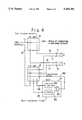
- FIG. 1 is a circuit diagram showing a time division switch of an embodiment of the present invention
- FIGS. 2A, 2B, 2C and 2D are timing diagrams showing the timing relationship between incoming and outgoing communication information in accordance with the switch shown in FIG. 1;
- FIG. 3 is a formatting diagram showing transferred information on the incoming and outgoing highways
- FIG. 4 is a circuit diagram using a time division switch shown in FIG. 8;
- FIG. 5 is another circuit diagram using a time division switch shown in FIG. 8;
- FIG. 6 is another circuit diagram using a time division switch shown in FIG. 8;
- FIGS. 7A, 7B, 7C and 7D are block diagrams showing states of the hand-over carried out by a conventional time division switch
- FIG. 8 is a circuit diagram showing the conventional time division switch
- FIGS. 9A, 9B, 9C and 9D are timing diagrams showing the timing relationship between incoming and outgoing communication information in accordance with the switch shown in FIG. 8;
- FIGS. 10A and 10B are timing diagrams showing the timing relationship between incoming and outgoing communication information in accordance with the switch shown in FIG. 8.
- FIG. 1 shows a time division switch 6 of the present invention including construction similar to the conventional switch shown in FIG. 8 already described above, therefore, the same reference numerals used in FIG. 8 are used in FIG. 1, reference numerals and constructions already described previously are also used and FIGS. 7A, 7B, 7C and 7D are used as reference for describing the embodiments.
- FIGS. 7A, 7B, 7C and 7D are used as reference for describing the embodiments.
- the first difference from FIG. 8 is that the time division switch 6 has a speech path memory 13, a write-address change switch 15 and a read-address change switch 17, which are exactly identical components shown in FIG. 1, also having a speech path memory 23, a write-address change switch 25 and a read-address change switch 27.
- These pairs of the speech path memories 13 and 23, the write-address change switches 15 and 25, and the read-address change switches 17 and 27 are connected with an incoming highway 11 and an outgoing highway 12, respectively, through frame change switches 43 and 44 which are switched at a frame-timing.
- the frame change switches 43 and 44 are switched by an output signal 41 of a most significant bit M of a counter 16 which counts timing of time slots.
- the most significant bit M alternately changes "1" and "0" at every frame, and is a type of adding one more bit to the most significant bit M of the counter 16 shown in FIG. 8.
- the outgoing highway 12 is connected with the reading side of the speech path memory 13 and in case of a frame which is connected with the speech path memory 13 to the incoming highway 11, the outgoing highway 12 is connected with the speech path memory 23, so that above connection operation is alternately carried out at every frame.
- the write-address change switches 15 and 25 and the read-address change switches 17 and 27 are actuated by reading results from an output C of the counter 18 and the connection control memory 14, respectively, thereby to be indicated its address in synchronization with each other.
- information of all time slots of a frame is written into either one of the speech path memories 13 or 23, in the following frame, the information is, in turn, read from one of the speech path memory 13 or 23 in the order of addresses indicated by the connection control memory 14.
- the incoming information of the time slot T2 of the frame F1 on the incoming highway 11 is transferred in duplication to the time slot T3 of the frame F1 and the time slot T1 of the frame F2 so as to switch between the frames F1 and F2 shown in FIGS. 9C and 9D, which does not retain the communication continuity.
- connection control memory 14 The second difference from FIG. 8 is that the writing information to the connection control memory 14 is not directly carried out from a micro processor 19, but the information is stored in a buffer memory 31 (referred to as BM in the drawings), then written into the connection control memory 14 in synchronization with timing of the time slots.
- BM buffer memory 31
- the information written into the buffer memory 31 through the data bus 20 and address bus 21 from the micro processor 19 is, in turn, read through the read-address change switch 33 and written into the connection control memory 14 through a gate 39 or 45 and the write-address change switch 37 for the connection control memory 14.
- the read-address change switch 33, the write-address change switch 37 and the read-address change switch 18 are all actuated by the output signal 42 from the output C of the counter 16 to act in sychronization with each other, but the read-address change switch 18 indicates an address which is one count preceding the address indication of the read-address change switch 33 and the write-address change switch 37.
- connection control memory 14 is updated at a timing of the following time slot after an address is read out therefrom, it is impossible to cause variation between the writing information to the connection control memory 14 and the timing of the information transfer to the outgoing highway 12 as described with the conventional time division switch 6 shown in FIG. 8.
- the third difference from FIG. 8 is that the time division switch 6 has a function which switches the connection in synchronization with the hand-over of the portable station 1.
- the function is carried out by a double-connection control memory 32 (referring to as DCM in the drawings), a D-flip flop circuit 38, an AND gates 39 and 45.
- a communication information format on the highway has a time-slot empty indication bit I/B representing whether a time slot is in use or not as shown in FIG. 3. That is, when changing from the state prior to the hand-over shown in FIG. 7B to the state of the hand-over termination shown in FIG. 7C, the time-slot empty indication bit I/B of a time slot which has transferred the last information received from the portable station 1 is turned to an empty indication (logical "1" in this case) by the fixed station 2.
- the time-slot empty indication bit I/B makes the D-flip flop 38 set through a conductor 46 shown in FIG. 1 thereby an output Q of the D-flip flop 38 is changed to the logical "1".
- the content of the double-connection control memory 32 corresponding to a time slot is the logical "1" (each address of the double-connection control memory 32 corresponds to 1-bit)
- the content of the buffer memory 31 is transferred to the connection control memory 14, and the communication channel is switched to a state which is indicated by the content of the buffer memory 31 from the following frame.
- the double-connection control memory 32 is a memory having a bit per each time slot, in the state of double connection shown, the state prior to the hand-over in FIG. 7B, and the state after the hand-over in FIG. 7C, the content of the connection control memory 14 can be previously set so that the highway directed from the PBX to the fixed stations 2 and 4 transfers a time slot corresponding to an address of either the speech path memory 13 or 23 on the incoming highway 11 to a time slot assigned to the connection with the fixed stations 2 and 4 on the outgoing highway 12.
- connection information for the communication channel in relation to the connection from the fixed station 4 to the PBX is stored in the buffer memory 31 and the logical "1" is supplied to the double-connection control memory 32 indicated by a corresponding address, and when the portable station 1 is switched the communication channel from fixed station 2 to fixed station 4, according to the time-slot empty indication bit I/B of the time slot which is just before transferred information from the fixed station 2, it is previously notified that the communication channel of the fixed station 2 becomes empty, so that the time division switch 6 is switched to the communication channel of the fixed station 4 from the following frame.
- FIGS. 4, 5 and 6 show other embodiments of the present invention.
- Each of the embodiments use a type of time division switch 6 shown in FIG. 8 which does not have the function (the third differences from FIG. 8 described above) for switching the communication channel in synchronization with the communication line switching of the portable station 1, or use a space division switch instead of the time division switch 6 shown in FIG. 1.
- FIG. 4 corresponds to FIG. 7A showing in speech
- FIG. 5 corresponding to FIGS. 7B and 7C showing the double connection
- FIG. 6 corresponding to FIG. 7D showing the operation after the hand-over.
- FIG. 4 shows a circuit diagram using the time division switch 6 shown in FIG. 8.
- both the incoming and outgoing highways 11 and 12 on the communication lines 7 corresponding to the fixed station 2 are connected with the PBX or a PSTN (Public Switched Telephone Network) through the time division switch 6.
- the fixed station 4 and a MCT (Multi-Convection Trunk) 51 are not connected with anywhere.
- a reference numeral 52 denotes a ISD (Idle Signal Detector), 53 denoting an OR gate, 54 and 55 denoting incoming lines. Remainder of reference numerals have been described previously.
- FIG. 5 shows another circuit diagram using the time division switch 6 shown in FIG. 8.
- the incoming highway 11 directed from the PBX and PSTN to the fixed stations 2 and 4 is connected in double with the outgoing highway 12 directed toward the fixed stations 2 and 4 by the time division switch 6, so that identical information is transferred to the fixed stations 2 and 4.
- the incoming highway 11 directed from the fixed stations 2 and 4 to the PBX and PSTN is connected with the incoming lines 54 and 55 of the multi-convection trunk 51 through the time division switch 6 and an outgoing line 56 of the multi-convection trunk 51 is connected with the outgoing highway 12 directed toward the PBX and PSTN through the time division switch 6.
- the idle signal detector 52 in the multi-convection trunk 51 examines an incoming signal. If the incoming signal does not have communication information, transferring operation is not carried out otherwise transferring the communication information to the outgoing highway 12.
- Examination of the incoming signal can be carried out by the time-slot empty indication bit I/B shown in FIG. 3. Also, when the incoming signal is not transmitted from the portable station 1, it can be determined that a logical "0" is supplied to all bits of the time slots.
- Each output of the idle signal detectors 52 in the multi-convection trunk 51 is operated by the logical sum, the output of which is transferred to the incoming highway 11 through the time division switch 6.
- the incoming line 54 connected with the multi-convection trunk 51 from the fixed station 2 since the incoming line 54 connected with the multi-convection trunk 51 from the fixed station 2 has communication information, the incoming line 54 is connected with the PBX and PSTN through the time division switch 6.
- the incoming line 55 connected with the multi-convection trunk 51 from the fixed station 4 is connected with the PBX and PSTN through the time division switch 6.
- FIG. 6 shows another circuit diagram using the time division switch 6 shown in FIG. 8.
- FIG. 6 corresponds to the state shown in FIG. 7D.
- the fixed station 4 is connected with the PBX and PSTN through the time division switch 6, and the fixed station 2 and multi-convection trunk 51 are not connected with anywhere.
- the duplication and loss of the communication information are eliminated and ensured the information continuity.
Landscapes
- Engineering & Computer Science (AREA)
- Computer Networks & Wireless Communication (AREA)
- Use Of Switch Circuits For Exchanges And Methods Of Control Of Multiplex Exchanges (AREA)
- Mobile Radio Communication Systems (AREA)
Abstract
Description
Claims (3)
Applications Claiming Priority (2)
| Application Number | Priority Date | Filing Date | Title |
|---|---|---|---|
| JP3155971A JP3032044B2 (en) | 1991-05-31 | 1991-05-31 | Instantaneous interruption switch switching method |
| JP3-155971 | 1991-05-31 |
Publications (1)
| Publication Number | Publication Date |
|---|---|
| US5353281A true US5353281A (en) | 1994-10-04 |
Family
ID=15617540
Family Applications (1)
| Application Number | Title | Priority Date | Filing Date |
|---|---|---|---|
| US07/889,952 Expired - Lifetime US5353281A (en) | 1991-05-31 | 1992-05-29 | Intermittenceless switching system |
Country Status (2)
| Country | Link |
|---|---|
| US (1) | US5353281A (en) |
| JP (1) | JP3032044B2 (en) |
Cited By (5)
| Publication number | Priority date | Publication date | Assignee | Title |
|---|---|---|---|---|
| US6330448B1 (en) * | 1998-04-16 | 2001-12-11 | Nec Corporation | Handover arrangement for mobile station moving across the boundary of wireless cell-site stations of adjacent PBXs |
| US6961343B1 (en) * | 1998-10-30 | 2005-11-01 | Fujitsu Limited | Cross-connection switch |
| US7042874B1 (en) * | 1999-08-27 | 2006-05-09 | Oki Electric Industry Co., Ltd | Digital switching system and method of switching data of same |
| CN108288441A (en) * | 2018-03-17 | 2018-07-17 | 广东迪艾生光电技术有限公司 | Analog SD card read-write system and city lighting engineering control system applied by same |
| US10716903B2 (en) | 2012-01-31 | 2020-07-21 | Altria Client Services Llc | Electronic cigarette |
Families Citing this family (2)
| Publication number | Priority date | Publication date | Assignee | Title |
|---|---|---|---|---|
| IT1272008B (en) * | 1993-03-11 | 1997-06-10 | Italtel Spa | METHOD FOR THE CHANGE OF TIME SLOT WITHOUT SOLUTION OF CONTINUITY IN THE VOICE SIGNAL (SEAMLESS HANDOVER) IN A DIGITAL SYSTEM OF PERSONAL TELEPHONE AND RADIO BASE STATION FOR THE IMPLEMENTATION OF THIS MATHODE. |
| US7116067B2 (en) | 2004-09-21 | 2006-10-03 | Honeywell International Inc. | Power converter controlling apparatus and method providing ride through capability during power interruption in a motor drive system |
Citations (4)
| Publication number | Priority date | Publication date | Assignee | Title |
|---|---|---|---|---|
| US4597079A (en) * | 1983-03-16 | 1986-06-24 | Fujitsu Limited | Redundant switchover system for TDMA satellite communication equipment |
| US4941141A (en) * | 1987-12-29 | 1990-07-10 | Nec Corporation | Time division switching for multi-channel calls using two time switch memories acting as a frame aligner |
| US5040174A (en) * | 1989-08-11 | 1991-08-13 | Nec Corporation | Time division speech path apparatus |
| US5042082A (en) * | 1989-06-26 | 1991-08-20 | Telefonaktiebolaget L. M. Ericsson | Mobile assisted handoff |
-
1991
- 1991-05-31 JP JP3155971A patent/JP3032044B2/en not_active Expired - Lifetime
-
1992
- 1992-05-29 US US07/889,952 patent/US5353281A/en not_active Expired - Lifetime
Patent Citations (4)
| Publication number | Priority date | Publication date | Assignee | Title |
|---|---|---|---|---|
| US4597079A (en) * | 1983-03-16 | 1986-06-24 | Fujitsu Limited | Redundant switchover system for TDMA satellite communication equipment |
| US4941141A (en) * | 1987-12-29 | 1990-07-10 | Nec Corporation | Time division switching for multi-channel calls using two time switch memories acting as a frame aligner |
| US5042082A (en) * | 1989-06-26 | 1991-08-20 | Telefonaktiebolaget L. M. Ericsson | Mobile assisted handoff |
| US5040174A (en) * | 1989-08-11 | 1991-08-13 | Nec Corporation | Time division speech path apparatus |
Cited By (5)
| Publication number | Priority date | Publication date | Assignee | Title |
|---|---|---|---|---|
| US6330448B1 (en) * | 1998-04-16 | 2001-12-11 | Nec Corporation | Handover arrangement for mobile station moving across the boundary of wireless cell-site stations of adjacent PBXs |
| US6961343B1 (en) * | 1998-10-30 | 2005-11-01 | Fujitsu Limited | Cross-connection switch |
| US7042874B1 (en) * | 1999-08-27 | 2006-05-09 | Oki Electric Industry Co., Ltd | Digital switching system and method of switching data of same |
| US10716903B2 (en) | 2012-01-31 | 2020-07-21 | Altria Client Services Llc | Electronic cigarette |
| CN108288441A (en) * | 2018-03-17 | 2018-07-17 | 广东迪艾生光电技术有限公司 | Analog SD card read-write system and city lighting engineering control system applied by same |
Also Published As
| Publication number | Publication date |
|---|---|
| JP3032044B2 (en) | 2000-04-10 |
| JPH04355594A (en) | 1992-12-09 |
Similar Documents
| Publication | Publication Date | Title |
|---|---|---|
| US4520477A (en) | Control information communication arrangement for a time division switching system | |
| EP0439926A2 (en) | Improved base station for mobile radio telecommunications systems | |
| US4688208A (en) | Time division exchange for carrying out a loop-back test | |
| US5128929A (en) | Time division switching system capable of broad band communications service | |
| US5353281A (en) | Intermittenceless switching system | |
| US4064370A (en) | Time-division switching system | |
| EP0116558B1 (en) | Control information communication arrangement for a time division switching system | |
| US4387466A (en) | Half-duplex digital transmission system | |
| EP0202205B1 (en) | Telecommunication system for alternatingly transmitting circuit-switched and packet-switched information | |
| US5309440A (en) | ISDN user-network interface system | |
| US3846587A (en) | Data transmission system for a multiple branch network | |
| US4105869A (en) | Time-division multiplex digital transmission system with intermediate stations adapted to transit insert and extract digital channels | |
| US3859465A (en) | Data transmission system with multiple access for the connected users | |
| US5475706A (en) | Bulk data transmission system | |
| US5165092A (en) | Method of processing the signalling information within configurable multiplexers | |
| KR910005471B1 (en) | Digital Button Telephone Device | |
| JP2675208B2 (en) | Broadcast communication control method | |
| JPH0736632B2 (en) | Time slot shift control system | |
| JPH0350927A (en) | Frame alinger and its control method | |
| JP2531821B2 (en) | DSI device | |
| JP2521957B2 (en) | Transmission system | |
| JP2563936B2 (en) | Loop communication system | |
| JP2595503B2 (en) | Time division multiplex time switch control method | |
| JPS59138197A (en) | Control circuit of time division multiplex network | |
| JPH04120928A (en) | Dsi device |
Legal Events
| Date | Code | Title | Description |
|---|---|---|---|
| AS | Assignment |
Owner name: HITACHI, LTD., JAPAN Free format text: ASSIGNMENT OF ASSIGNORS INTEREST.;ASSIGNORS:KUWAHARA, HIROSHI;SUZUKI, KAZUHIRO;SASA, TOSHIKAZU;AND OTHERS;REEL/FRAME:006188/0114 Effective date: 19920625 Owner name: KOKUSAI ELECTRIC CO., LTD., JAPAN Free format text: ASSIGNMENT OF ASSIGNORS INTEREST.;ASSIGNORS:KUWAHARA, HIROSHI;SUZUKI, KAZUHIRO;SASA, TOSHIKAZU;AND OTHERS;REEL/FRAME:006188/0114 Effective date: 19920625 |
|
| STCF | Information on status: patent grant |
Free format text: PATENTED CASE |
|
| FPAY | Fee payment |
Year of fee payment: 4 |
|
| AS | Assignment |
Owner name: HITACHI KOKUSAI ELECTRIC INC., JAPAN Free format text: CHANGE OF NAME;ASSIGNOR:KOKUSAI ELECTRIC CO., LTD.;REEL/FRAME:011467/0171 Effective date: 20001002 |
|
| FPAY | Fee payment |
Year of fee payment: 8 |
|
| REMI | Maintenance fee reminder mailed | ||
| FPAY | Fee payment |
Year of fee payment: 12 |