US535262A - Spark-arrester - Google Patents
Spark-arrester Download PDFInfo
- Publication number
- US535262A US535262A US535262DA US535262A US 535262 A US535262 A US 535262A US 535262D A US535262D A US 535262DA US 535262 A US535262 A US 535262A
- Authority
- US
- United States
- Prior art keywords
- sheet
- plate
- arrester
- spark
- sparks
- Prior art date
- Legal status (The legal status is an assumption and is not a legal conclusion. Google has not performed a legal analysis and makes no representation as to the accuracy of the status listed.)
- Expired - Lifetime
Links
- 239000000779 smoke Substances 0.000 description 11
- 239000000463 material Substances 0.000 description 5
- 230000003137 locomotive effect Effects 0.000 description 2
- 230000001174 ascending effect Effects 0.000 description 1
- 239000003245 coal Substances 0.000 description 1
- 238000010276 construction Methods 0.000 description 1
- 239000000428 dust Substances 0.000 description 1
- 206010022000 influenza Diseases 0.000 description 1
- 239000002184 metal Substances 0.000 description 1
Images
Classifications
-
- F—MECHANICAL ENGINEERING; LIGHTING; HEATING; WEAPONS; BLASTING
- F23—COMBUSTION APPARATUS; COMBUSTION PROCESSES
- F23J—REMOVAL OR TREATMENT OF COMBUSTION PRODUCTS OR COMBUSTION RESIDUES; FLUES
- F23J15/00—Arrangements of devices for treating smoke or fumes
- F23J15/02—Arrangements of devices for treating smoke or fumes of purifiers, e.g. for removing noxious material
- F23J15/022—Arrangements of devices for treating smoke or fumes of purifiers, e.g. for removing noxious material for removing solid particulate material from the gasflow
Definitions
- meniarw 4 iv g5 UNITED STATES I PATENT EEICE.
- My invention has relation to spark arresters adapted especially to be applied to locomotive engines, and it consists in the novel construction and arrangement of its parts as hereinafter described.
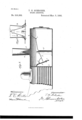
- Figure 1 represents the forward end of a locomotive boiler partly in section, and showing the spark arrester.
- Fig. 2 is a detail view of a secondary arrester.
- the deflected sheet metal plate 1 is secured in front of the boiler flues 2. Said plate extends all the way across the smoke box, and it'has secured to its lower end the sliding plate 3, said sliding plate having an elongated perforation by means of which it can be raised or lowered and secured in place by the bolt and nut attached to the plate 1, and passing through said elongated perforation.
- the perforated sheet 4 extends generally in a diagonal line across the front end of the smoke box.
- the rear end of said sheet extends to, within a short distance of the plate 1, and the front part of said sheet 4, is hinged at- 5, and is held in place by the catch 6, attached to the side of the smoke box.
- the plate 1, and the sheet 4 form what may be termed an exaggerated funnel.
- a second perforated sheet 7, is secured to the plate 1, and said sheet 7, extends over the opening between the said plate 1, and the end of the sheet 4, and said sheet 7, extends to within a short distance of the sheet 4.
- Said sheet 7, is preferably convexed on its upper surface, as shown.
- the exhaust steam nozzle 8, extends up through the sheet 4, and the end of said nozzle is directly under the stack 9.
- An additional arrester 10, is located in said stack.
- Said additional or secondary arrester consists of a sheet of perforated material formed into a hollow cone or a pyramid, with the opening 11, at the top. The said opening 11, is above the end of the steam n0zzle 8, and the steam from said nozzle passes through said opening.
- FIG. 2 shows arrester 10, attached to the stack, and having a space between the sides of the stack and the lower end of the arrester.
- the device acts as follows: The smoke, sparks, 850., come from the fines 2, and are deflected down by the plate 1, the plate 3, having been previously adjusted to regulate the draft. The larger sparks will strike the said plate and will fall to the bottom of the smoke box, but some of the finer sparks will follow the draft, and as the smoke, &c., passes the front of the smoke box preparatory to ascending and passing out of the stack, the most of the said finer sparks will strike against the perforated sheet 4, at an angle and will glance off to the bottom of the smoke box.
- the secondary arrester 10' in the stack is designed to arrest any sparks that should be carried up by the jet from the steam nozzle 8. The sparks will either strike against the sides of the arrester 10, and be rejected or they will strike the sides and be pulverized and pass off as dust.
- a spark arrester consisting of a metallic plate placed in front of the fiues; a sheet of perforated material located between the lower end of the metallic plate and the stack, said perforated sheet extending to within a short distance of said Inetallic plate and having an opening between the end thereof and said plate; a second sheet of perforated material located over the opening between the metallic plate and the first said sheet of perforated material, said second sheet of perforated material extending from the metallic plate to Within a short distance of the first perforated sheet and having an IQ opening between the end thereof and said first perforated plate, as set forth.
Landscapes
- Engineering & Computer Science (AREA)
- Mechanical Engineering (AREA)
- General Engineering & Computer Science (AREA)
- Preliminary Treatment Of Fibers (AREA)
Description
(No Model.)
T. H. SCHRODER.
SPARK ARRESTER.
. No. 535,262. Patented Mar. 5,1895.
meniarw 4 (iv g5 UNITED STATES I PATENT EEICE.
THOMAS H. SOHRODER, OF JACKSON, TENNESSEE.
SPARK-ARRESTER.
SPECIFICATION formingpart of Letters Patent No. 535,262, dated March 5, 1895.
" Application filed November 15, 1894- Serial No. 528,925. (No model.)
To all whom it may concern:
Be it known that I, THOMAS H. SOHRODER, a citizen of the United States, residing at Jackson, in the county of Madison and State of Tennessee, have invented a certain new, useful, and valuable Improvement in Spark- Arresters, of which the following is a full, clear, and. exact description.
My invention has relation to spark arresters adapted especially to be applied to locomotive engines, and it consists in the novel construction and arrangement of its parts as hereinafter described.
In the accompanying drawings, Figure 1 represents the forward end of a locomotive boiler partly in section, and showing the spark arrester. Fig. 2 is a detail view of a secondary arrester.
The deflected sheet metal plate 1, is secured in front of the boiler flues 2. Said plate extends all the way across the smoke box, and it'has secured to its lower end the sliding plate 3, said sliding plate having an elongated perforation by means of which it can be raised or lowered and secured in place by the bolt and nut attached to the plate 1, and passing through said elongated perforation.
The perforated sheet 4, extends generally in a diagonal line across the front end of the smoke box. The rear end of said sheet extends to, within a short distance of the plate 1, and the front part of said sheet 4, is hinged at- 5, and is held in place by the catch 6, attached to the side of the smoke box. Thus the plate 1, and the sheet 4, form what may be termed an exaggerated funnel.
A second perforated sheet 7, is secured to the plate 1, and said sheet 7, extends over the opening between the said plate 1, and the end of the sheet 4, and said sheet 7, extends to within a short distance of the sheet 4. Said sheet 7, is preferably convexed on its upper surface, as shown. The exhaust steam nozzle 8, extends up through the sheet 4, and the end of said nozzle is directly under the stack 9. An additional arrester 10, is located in said stack. Said additional or secondary arrester consists of a sheet of perforated material formed into a hollow cone or a pyramid, with the opening 11, at the top. The said opening 11, is above the end of the steam n0zzle 8, and the steam from said nozzle passes through said opening.
The detail view (Fig. 2) shows arrester 10, attached to the stack, and having a space between the sides of the stack and the lower end of the arrester.
In operation the device acts as follows: The smoke, sparks, 850., come from the fines 2, and are deflected down by the plate 1, the plate 3, having been previously adjusted to regulate the draft. The larger sparks will strike the said plate and will fall to the bottom of the smoke box, but some of the finer sparks will follow the draft, and as the smoke, &c., passes the front of the smoke box preparatory to ascending and passing out of the stack, the most of the said finer sparks will strike against the perforated sheet 4, at an angle and will glance off to the bottom of the smoke box. Should some of the finer sparks pass through the perforations in the sheet 4, they will be carried back and will fall upon the sheet 7, and will then pass through the opening between said sheet 7, and sheet 4, and they will then pass through the opening between sheet 4, and the plate 1, and will fall into the smoke box. The secondary arrester 10', in the stack is designed to arrest any sparks that should be carried up by the jet from the steam nozzle 8. The sparks will either strike against the sides of the arrester 10, and be rejected or they will strike the sides and be pulverized and pass off as dust.
Should any sparks get behind the arrester 10, they will fall down into the smoke box. See detail view Fig. 2.
By placing the perforated sheets on an incline as shown they are not so liable to be clogged up by sparks lodging therein, and hence the draft is not interfered with. Therefore this sparkarrester is an economizer of heat and coal as the fire will always have a good draft.
Having described my invention, what I claim as new, and desire to secure by Letters Patent, is-
In combination with a boiler having fines, smoke box and stack, a spark arrester consisting of a metallic plate placed in front of the fiues; a sheet of perforated material located between the lower end of the metallic plate and the stack, said perforated sheet extending to within a short distance of said Inetallic plate and having an opening between the end thereof and said plate; a second sheet of perforated material located over the opening between the metallic plate and the first said sheet of perforated material, said second sheet of perforated material extending from the metallic plate to Within a short distance of the first perforated sheet and having an IQ opening between the end thereof and said first perforated plate, as set forth.
In testimony whereof I affix my signature in presence of two witnesses.
THOMAS H. SOHRODER. Witnesses:
H. D. BURNELL, M. B. HURT.
Publications (1)
| Publication Number | Publication Date |
|---|---|
| US535262A true US535262A (en) | 1895-03-05 |
Family
ID=2604023
Family Applications (1)
| Application Number | Title | Priority Date | Filing Date |
|---|---|---|---|
| US535262D Expired - Lifetime US535262A (en) | Spark-arrester |
Country Status (1)
| Country | Link |
|---|---|
| US (1) | US535262A (en) |
-
0
- US US535262D patent/US535262A/en not_active Expired - Lifetime
Similar Documents
| Publication | Publication Date | Title |
|---|---|---|
| US535262A (en) | Spark-arrester | |
| US851494A (en) | Spark-arrester. | |
| US880309A (en) | Spark-arrester. | |
| US1118844A (en) | Spark-arrester. | |
| US2104958A (en) | Smoke box structure | |
| US144932A (en) | Improvement in spark-arresters | |
| US880442A (en) | Spark-arrester. | |
| US607927A (en) | Spark-arrester | |
| US473235A (en) | Spark-arrester | |
| US448918A (en) | William b | |
| US854016A (en) | Spark-arrester. | |
| US265343A (en) | A tptt tvt t | |
| US588096A (en) | Spark-arrester | |
| US1091283A (en) | Spark-arrester. | |
| US813493A (en) | Spark-arrester. | |
| US128693A (en) | Improvement in spark-arresters | |
| US971823A (en) | Spark-arrester. | |
| US940955A (en) | Spark-arrester. | |
| US393994A (en) | Spark-arrester | |
| US427955A (en) | Spark-arrester | |
| US852727A (en) | Spark-arrester. | |
| US245621A (en) | Samuel l | |
| US314697A (en) | Spark arrester and consumer | |
| US409344A (en) | Spark-arrester | |
| US252239A (en) | Office |