US5350309A - Connector with a protective cover - Google Patents

Connector with a protective cover Download PDF

Info

Publication number
US5350309A
US5350309A US08/035,924 US3592493A US5350309A US 5350309 A US5350309 A US 5350309A US 3592493 A US3592493 A US 3592493A US 5350309 A US5350309 A US 5350309A
Authority
US
United States
Prior art keywords
connector
housing
opening
arms
protective cover
Prior art date
Legal status (The legal status is an assumption and is not a legal conclusion. Google has not performed a legal analysis and makes no representation as to the accuracy of the status listed.)
Expired - Fee Related
Application number
US08/035,924
Inventor
Yukihiro Abukawa
Hiraji Takase
Yasuhisa Shinji
Current Assignee (The listed assignees may be inaccurate. Google has not performed a legal analysis and makes no representation or warranty as to the accuracy of the list.)
Isuzu Motors Ltd
Yazaki Corp
Original Assignee
Isuzu Motors Ltd
Yazaki Corp
Priority date (The priority date is an assumption and is not a legal conclusion. Google has not performed a legal analysis and makes no representation as to the accuracy of the date listed.)
Filing date
Publication date
Application filed by Isuzu Motors Ltd, Yazaki Corp filed Critical Isuzu Motors Ltd
Assigned to ISUZU MOTORS LIMITED, YAZAKI CORPORATION reassignment ISUZU MOTORS LIMITED ASSIGNMENT OF ASSIGNORS INTEREST (SEE DOCUMENT FOR DETAILS). Assignors: ABUKAWA, YUKIHIRO, SHINJI, YASUHISA, TAKASE, HORAJI
Application granted granted Critical
Publication of US5350309A publication Critical patent/US5350309A/en
Anticipated expiration legal-status Critical
Expired - Fee Related legal-status Critical Current

Links

Images

Classifications

    • HELECTRICITY
    • H01ELECTRIC ELEMENTS
    • H01RELECTRICALLY-CONDUCTIVE CONNECTIONS; STRUCTURAL ASSOCIATIONS OF A PLURALITY OF MUTUALLY-INSULATED ELECTRICAL CONNECTING ELEMENTS; COUPLING DEVICES; CURRENT COLLECTORS
    • H01R13/00Details of coupling devices of the kinds covered by groups H01R12/70 or H01R24/00 - H01R33/00
    • H01R13/44Means for preventing access to live contacts
    • H01R13/447Shutter or cover plate
    • HELECTRICITY
    • H01ELECTRIC ELEMENTS
    • H01RELECTRICALLY-CONDUCTIVE CONNECTIONS; STRUCTURAL ASSOCIATIONS OF A PLURALITY OF MUTUALLY-INSULATED ELECTRICAL CONNECTING ELEMENTS; COUPLING DEVICES; CURRENT COLLECTORS
    • H01R12/00Structural associations of a plurality of mutually-insulated electrical connecting elements, specially adapted for printed circuits, e.g. printed circuit boards [PCB], flat or ribbon cables, or like generally planar structures, e.g. terminal strips, terminal blocks; Coupling devices specially adapted for printed circuits, flat or ribbon cables, or like generally planar structures; Terminals specially adapted for contact with, or insertion into, printed circuits, flat or ribbon cables, or like generally planar structures
    • H01R12/70Coupling devices
    • H01R12/7005Guiding, mounting, polarizing or locking means; Extractors
    • H01R12/7011Locking or fixing a connector to a PCB
    • H01R12/7017Snap means
    • H01R12/7023Snap means integral with the coupling device
    • HELECTRICITY
    • H01ELECTRIC ELEMENTS
    • H01RELECTRICALLY-CONDUCTIVE CONNECTIONS; STRUCTURAL ASSOCIATIONS OF A PLURALITY OF MUTUALLY-INSULATED ELECTRICAL CONNECTING ELEMENTS; COUPLING DEVICES; CURRENT COLLECTORS
    • H01R13/00Details of coupling devices of the kinds covered by groups H01R12/70 or H01R24/00 - H01R33/00
    • H01R13/46Bases; Cases
    • H01R13/52Dustproof, splashproof, drip-proof, waterproof, or flameproof cases
    • H01R13/5213Covers
    • HELECTRICITY
    • H01ELECTRIC ELEMENTS
    • H01RELECTRICALLY-CONDUCTIVE CONNECTIONS; STRUCTURAL ASSOCIATIONS OF A PLURALITY OF MUTUALLY-INSULATED ELECTRICAL CONNECTING ELEMENTS; COUPLING DEVICES; CURRENT COLLECTORS
    • H01R12/00Structural associations of a plurality of mutually-insulated electrical connecting elements, specially adapted for printed circuits, e.g. printed circuit boards [PCB], flat or ribbon cables, or like generally planar structures, e.g. terminal strips, terminal blocks; Coupling devices specially adapted for printed circuits, flat or ribbon cables, or like generally planar structures; Terminals specially adapted for contact with, or insertion into, printed circuits, flat or ribbon cables, or like generally planar structures
    • H01R12/50Fixed connections
    • H01R12/59Fixed connections for flexible printed circuits, flat or ribbon cables or like structures
    • HELECTRICITY
    • H01ELECTRIC ELEMENTS
    • H01RELECTRICALLY-CONDUCTIVE CONNECTIONS; STRUCTURAL ASSOCIATIONS OF A PLURALITY OF MUTUALLY-INSULATED ELECTRICAL CONNECTING ELEMENTS; COUPLING DEVICES; CURRENT COLLECTORS
    • H01R2201/00Connectors or connections adapted for particular applications
    • H01R2201/20Connectors or connections adapted for particular applications for testing or measuring purposes
    • HELECTRICITY
    • H01ELECTRIC ELEMENTS
    • H01RELECTRICALLY-CONDUCTIVE CONNECTIONS; STRUCTURAL ASSOCIATIONS OF A PLURALITY OF MUTUALLY-INSULATED ELECTRICAL CONNECTING ELEMENTS; COUPLING DEVICES; CURRENT COLLECTORS
    • H01R2201/00Connectors or connections adapted for particular applications
    • H01R2201/26Connectors or connections adapted for particular applications for vehicles

Definitions

  • the present invention relates to a direct insertion type connector with a protective cover, which connector is fitted into an electrical circuit fabricated on a FPC in an electric apparatus such as a meter case for an automotive vehicle.
  • FIG. 5 is a perspective view of a conventional direct insertion type connector a.
  • a housing 21 made of a synthetic resin is provided with an opening 22 on one side wall thereof through which resilient contacts 24 of terminals 23 are closed.
  • a locking arm 25 (FIG. 4B) includes a projection 25a.
  • FIG. 6 shows a cross section of the connector a in FIG. 5 when the connector a is fully fitted into a recess 27 of a meter case b.
  • An FPC 28 is provided on the inner wall of the recess 27. When the connector a is fully inserted into the recess 27, the resilient contacts 24 become in contact with contacts 20 of the FPC 28 to make electrical contact.
  • the locking arm 25 of the connector a engages a hook 30 on the inner wall of the recess 27, so that the connector a is locked in place.
  • the connector a is inserted into a protective cover c as shown in FIG. 7 until the connector a is inserted into a mating case b as shown in FIG. 8, so that the electrical contacts 24 are protected from soiling and accidental contact with other electrically conductive elements.
  • the protective cover c is disposable and therefore put aside after mounting the connector a into the meter case b. If the connector a is drawn at a later time from the meter case for inspection, the terminals 23 are exposed as shown in FIG. 5.
  • FIG. 9 shows another conventional direct insertion type connector a' disclosed in Japanese Utility Model Preliminary Publication No. 53-163585.
  • a housing 21' is provided with an opening 22' on each of the opposed sides of a front half thereof. Resilient contacts 24' of terminals 23' are exposed through the openings 21'.
  • the opening 22' is provided with a cover 31.
  • the cover 31 includes a locking latch 32 that serves to lock the connector a' to the meter case when inserted into the meter case. This construction necessitates a mating engagement on the meter case with which the locking latch 32 is engaged. Further, providing the mating engagement on the meter case places limitations on the FPC layout and therefore results in a larger meter case.
  • An object of the present invention is to provide a connector with an attached protective cover where the connector may be mounted to a meter case and the protective cover protects the connector from damage when disconnected from the meter case.
  • the connector includes a housing having an opening formed on one side thereof through which electrical contacts of terminals are exposed.
  • the protective cover includes an insulating protector for covering the opening of the connector and a housing holder detachably assembled to the housing.
  • the insulating protector has a protective plate and two arms extending in the same direction from the longitudinal ends of the protective plate. Each of the arms has a projection and is rotatably assembled at distal end thereof to the housing holder.
  • the housing holder has a closed-position locking groove and an opened-position locking groove, which are provided about rotating axis of the arms and angularly spaced apart from each other.
  • the protective plate closes the opening of the connector A when the projection is received in the closed-position locking groove, and opens the opening when the projection is received in the opened-position locking groove.
  • FIGS. 1A and 1B are perspective views of a connector and a protective cover therefore according to the present invention
  • FIG. 2 is a side view of the connector of FIGS. 1A-1B with the protective cover assembled to the connector, showing a cross section in part;
  • FIG. 3 is a cross-sectional view of the connector and the meter case immediately before the connector is inserted into the meter case;
  • FIG. 4A shows the connector of FIG. 3 after the connector has been inserted into the meter case
  • FIG. 4B shows the detail of a locking arm 25 and a projection 25a
  • FIG. 5 is a perspective view of a conventional director insertion type connector
  • FIG. 6 is a cross-sectional view of the connector of FIG. 5 fitted into the meter case
  • FIG. 7 is a perspective view of a protective cover for a conventional connector
  • FIG. 8 is a cross-sectional view of the connector of FIG. 7 when fitted to the protective cover of FIG. 7;
  • FIG. 9 is a perspective view of another conventional direct insertion type connector.
  • FIG. 1A is a perspective view of a connector A.
  • the connector A has a housing 21 having an opening 22 on one of opposed side walls and a locking arm 25 (FIG. 2) with a projection 25a (FIG. 3) on the other.
  • the housing 21 houses terminals 23 crimped to wires 26. Resilient electrical contacts 24 of the terminals 23 are exposed through the opening 22 provided on one of the opposed side walls of the housing.
  • the housing 21 is also provided with recesses 17 which engage projections 6 of the connector cover B.
  • FIG. 1A shows one of the engaging recesses 17.
  • FIG. 1B is a perspective view of a protective cover made of a synthetic resin.
  • the protective cover B includes an insulating protector 2 and a housing holder 1 which is mounted on the upper half portion of the housing 21 of the connector A.
  • the housing holder 1 is integrally continuous with the insulating protector 2 via a hinge 3 having a thick portion 4 theft defines a desired curved shape of hinge 3 after connector A is assembled to the circuit.
  • FIGS. 4C-4D show different positions of the thick portion 4 on the hinge 3.
  • the housing holder 1 is a generally U-shaped frame having a longitudinal side wall 1a and short walls 1b at each of longitudinal ends of the side wall 1a.
  • the short walls 1b each have a hook 1c at a free end thereof and a shaft 12 projecting outwardly from the short walls 1b.
  • Each hook 1c has a tip end extending toward the longitudinal side wall 1a as shown in FIG. 1B.
  • Below the shaft 12 are formed radially extending grooves 13 and 14 which are angularly spaced.
  • the groove 13 serves as a closed-position locking groove while the groove 14 serves as an opened-position locking groove.
  • At the lower ends of the longitudinal wall 1a and short walls 1b are provided with projections 5 and 6, respectively.
  • the longitudinal side wall 1a is formed with two parallel slits 9 therein as shown in FIG. 1B.
  • the insulating protector 2 includes a protective plate 2a and two arms 2b formed on the longitudinal ends of the protective plate 2a.
  • the two arms 2b extend transversely of the protective plate 2a in the same direction.
  • the two arms 2b are assembled to the housing holder 1 such that the shaft 12 projecting outwardly from the walls 1b extends through holes 10 in the arms 2b.
  • the two arms 2b become rotatable about the shaft 12.
  • the arms 2b each have a projection 11 which drops into the closed-position locking groove 13 or into the opened-position locking groove 14 in a locking relation when rotated about the shaft 12.
  • the closed-position locking groove 13 receives the projection 11 so that the protective plate 2a is positioned to close the opening 22 of the connector A when the connector A is not inserted into the meter case
  • the opened-position locking groove 14 receives the projection 11 so that the protective plate 2a is positioned to uncover the opening upon insertion of the connector A into the meter case.
  • the connector A is inserted into the housing holder 1 in the direction of arrow Q with the opening 22 facing the resilient lock arm 8 of the housing holder 1.
  • the upper edge of the housing 21 cams the projections 7 of the resilient lock arm 8 laterally out of the way so that the resilient lock arm 8 yieldably deflects.
  • the resilient arm 8 returns to its normal position after the connector A has been fully inserted into the housing holder 1.
  • the recesses 16 and 17 abut the projections 5 and 6 of the housing holder 1 and the projections latch the housing 21 so that the connector A fits the housing holder 1 in a locking relation.
  • the arms 2b are journaled to the shafts 12 of the housing holder 1.
  • Rotating the arms 2b toward the connector A causes the projection 11 to drop into the locking groove 13, so that the protective plate 2a covers the opening 22 with the arms 2b locked in the groove 13.
  • the protective plate 2a isolates the resilient electrical contacts 24 of the terminals 23 from the outside.
  • FIG. 4B shows the detail of the locking arm 25 and the projection 25a. Meanwhile, the projection 11 engages the opened-position locking groove 14 so that the insulating protector 2 is locked in place.
  • the insulating protector can be returned manually to its home position.
  • the repelling force of the hinge 3 urges the insulating protector 2 in the direction of arrow R against the meter case b, further preventing the insulating protector 2 from rattling.
  • the hinges 3 may be omitted.
  • the shafts 12 may be provided on the arms 2b and the holes 10 may be provided in the housing holder 1.
  • a plurality of opened-position locking grooves 14 may be provided at different angular positions taking into account the opening angles of the protective plate 2a as well as different fitting depth between the connector A and the meter case b.

Abstract

A connector with a protective cover for exposed electrical terminals. The connector includes a housing having an opening formed on one side thereof through which electrical contacts of terminals are exposed. The protective cover includes an insulating protector for covering the opening of the connector and a housing holder detachably assembled to the housing. The insulating protector has a protective plate and two arms extending in the same direction from the longitudinal ends of the protective plate. Each of the arms has a projection and is rotatably assembled at distal end thereof to the housing holder. The housing holder has a closing-position locking groove and an opening-position locking groove, which are provided about rotating axis of the arms and angularly spaced apart from each other. The protective plate closes the opening of the connector A when the projection is received in the closing-position locking groove, and opens the opening when the projection is received in the opening-position locking groove.

Description

BACKGROUND OF THE INVENTION
1. Field of the Invention
The present invention relates to a direct insertion type connector with a protective cover, which connector is fitted into an electrical circuit fabricated on a FPC in an electric apparatus such as a meter case for an automotive vehicle.
2. Prior Art
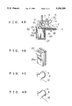
FIG. 5 is a perspective view of a conventional direct insertion type connector a. A housing 21 made of a synthetic resin is provided with an opening 22 on one side wall thereof through which resilient contacts 24 of terminals 23 are closed. A locking arm 25 (FIG. 4B) includes a projection 25a. FIG. 6 shows a cross section of the connector a in FIG. 5 when the connector a is fully fitted into a recess 27 of a meter case b. An FPC 28 is provided on the inner wall of the recess 27. When the connector a is fully inserted into the recess 27, the resilient contacts 24 become in contact with contacts 20 of the FPC 28 to make electrical contact. At this time, the locking arm 25 of the connector a engages a hook 30 on the inner wall of the recess 27, so that the connector a is locked in place. The connector a is inserted into a protective cover c as shown in FIG. 7 until the connector a is inserted into a mating case b as shown in FIG. 8, so that the electrical contacts 24 are protected from soiling and accidental contact with other electrically conductive elements. The protective cover c is disposable and therefore put aside after mounting the connector a into the meter case b. If the connector a is drawn at a later time from the meter case for inspection, the terminals 23 are exposed as shown in FIG. 5. This is dangerous because the contacts 24 may inadvertently contact the vehicle body or the metallic panel to cause short-circuit or mechanical damages to the terminals. Of course, the workman should follow the safety instructions, for example, disconnecting the battery from the electrical circuit when carrying out maintenance operations. If, however, the workman fails to follow such instructions, the connector a with the aforementioned construction is in potential danger.
FIG. 9 shows another conventional direct insertion type connector a' disclosed in Japanese Utility Model Preliminary Publication No. 53-163585. In FIG. 9, a housing 21' is provided with an opening 22' on each of the opposed sides of a front half thereof. Resilient contacts 24' of terminals 23' are exposed through the openings 21'. The opening 22' is provided with a cover 31. The cover 31 includes a locking latch 32 that serves to lock the connector a' to the meter case when inserted into the meter case. This construction necessitates a mating engagement on the meter case with which the locking latch 32 is engaged. Further, providing the mating engagement on the meter case places limitations on the FPC layout and therefore results in a larger meter case.
SUMMARY OF THE INVENTION
An object of the present invention is to provide a connector with an attached protective cover where the connector may be mounted to a meter case and the protective cover protects the connector from damage when disconnected from the meter case.
The connector includes a housing having an opening formed on one side thereof through which electrical contacts of terminals are exposed. The protective cover includes an insulating protector for covering the opening of the connector and a housing holder detachably assembled to the housing. The insulating protector has a protective plate and two arms extending in the same direction from the longitudinal ends of the protective plate. Each of the arms has a projection and is rotatably assembled at distal end thereof to the housing holder. The housing holder has a closed-position locking groove and an opened-position locking groove, which are provided about rotating axis of the arms and angularly spaced apart from each other. The protective plate closes the opening of the connector A when the projection is received in the closed-position locking groove, and opens the opening when the projection is received in the opened-position locking groove.
BRIEF DESCRIPTION OF THE DRAWINGS
Features and other objects of the present invention will become more apparent from the detailed description of the preferred embodiments with reference to the drawings in which:
FIGS. 1A and 1B are perspective views of a connector and a protective cover therefore according to the present invention;
FIG. 2 is a side view of the connector of FIGS. 1A-1B with the protective cover assembled to the connector, showing a cross section in part;
FIG. 3 is a cross-sectional view of the connector and the meter case immediately before the connector is inserted into the meter case;
FIG. 4A shows the connector of FIG. 3 after the connector has been inserted into the meter case;
FIG. 4B shows the detail of a locking arm 25 and a projection 25a;
FIGS. 4C-4D show the different positions of a thick portion 4 on a hinge 3;
FIG. 5 is a perspective view of a conventional director insertion type connector;
FIG. 6 is a cross-sectional view of the connector of FIG. 5 fitted into the meter case;
FIG. 7 is a perspective view of a protective cover for a conventional connector;
FIG. 8 is a cross-sectional view of the connector of FIG. 7 when fitted to the protective cover of FIG. 7; and
FIG. 9 is a perspective view of another conventional direct insertion type connector.
DETAILED DESCRIPTION OF THE PREFERRED EMBODIMENTS Construction
FIG. 1A is a perspective view of a connector A. The connector A has a housing 21 having an opening 22 on one of opposed side walls and a locking arm 25 (FIG. 2) with a projection 25a (FIG. 3) on the other. The housing 21 houses terminals 23 crimped to wires 26. Resilient electrical contacts 24 of the terminals 23 are exposed through the opening 22 provided on one of the opposed side walls of the housing. The housing 21 is also provided with recesses 17 which engage projections 6 of the connector cover B. FIG. 1A shows one of the engaging recesses 17.
FIG. 1B is a perspective view of a protective cover made of a synthetic resin. The protective cover B includes an insulating protector 2 and a housing holder 1 which is mounted on the upper half portion of the housing 21 of the connector A. The housing holder 1 is integrally continuous with the insulating protector 2 via a hinge 3 having a thick portion 4 theft defines a desired curved shape of hinge 3 after connector A is assembled to the circuit. FIGS. 4C-4D show different positions of the thick portion 4 on the hinge 3. The housing holder 1 is a generally U-shaped frame having a longitudinal side wall 1a and short walls 1b at each of longitudinal ends of the side wall 1a. The short walls 1b each have a hook 1c at a free end thereof and a shaft 12 projecting outwardly from the short walls 1b. Each hook 1c has a tip end extending toward the longitudinal side wall 1a as shown in FIG. 1B. Below the shaft 12 are formed radially extending grooves 13 and 14 which are angularly spaced. The groove 13 serves as a closed-position locking groove while the groove 14 serves as an opened-position locking groove. At the lower ends of the longitudinal wall 1a and short walls 1b are provided with projections 5 and 6, respectively. The longitudinal side wall 1a is formed with two parallel slits 9 therein as shown in FIG. 1B. Parallel slits 9 define a resilient lock arm 8 therebetween for latching the housing of the connector A when the connector A is assembled to the protective cover B. The insulating protector 2 includes a protective plate 2a and two arms 2b formed on the longitudinal ends of the protective plate 2a. The two arms 2b extend transversely of the protective plate 2a in the same direction. The two arms 2b are assembled to the housing holder 1 such that the shaft 12 projecting outwardly from the walls 1b extends through holes 10 in the arms 2b. Thus, the two arms 2b become rotatable about the shaft 12. As shown in FIG. 1B, the arms 2b each have a projection 11 which drops into the closed-position locking groove 13 or into the opened-position locking groove 14 in a locking relation when rotated about the shaft 12. The closed-position locking groove 13 receives the projection 11 so that the protective plate 2a is positioned to close the opening 22 of the connector A when the connector A is not inserted into the meter case, The opened-position locking groove 14 receives the projection 11 so that the protective plate 2a is positioned to uncover the opening upon insertion of the connector A into the meter case.
Operation
As shown in FIGS. 1A and 1B, the connector A is inserted into the housing holder 1 in the direction of arrow Q with the opening 22 facing the resilient lock arm 8 of the housing holder 1. When the connector A is further inserted into the housing holder 1, the upper edge of the housing 21 cams the projections 7 of the resilient lock arm 8 laterally out of the way so that the resilient lock arm 8 yieldably deflects. The resilient arm 8 returns to its normal position after the connector A has been fully inserted into the housing holder 1. At this time, the recesses 16 and 17 abut the projections 5 and 6 of the housing holder 1 and the projections latch the housing 21 so that the connector A fits the housing holder 1 in a locking relation.
Then, the arms 2b are journaled to the shafts 12 of the housing holder 1. Rotating the arms 2b toward the connector A causes the projection 11 to drop into the locking groove 13, so that the protective plate 2a covers the opening 22 with the arms 2b locked in the groove 13. In this manner, the protective plate 2a isolates the resilient electrical contacts 24 of the terminals 23 from the outside.
When the thus assembled connector A with the protective cover B is plugged into the recess 27 in the meter case b, a tip end P1 (FIG. 3) of the arm 2b abuts a surface P2 of the meter case b to produce an upward moment which releases the projection 11 from a locking relation with the locking groove 13. At this time, the insulating protector 2 rotates to open the opening 22. A further insertion of the connector A into the recess 27 accomplishes electrical contact between the resilient electrical contacts 24 of the connector A and terminals 29 of an FPC 28. Then, the projection 25a of the connector A engages the portion 30 of the recess 27 in a locking relation. FIG. 4B shows the detail of the locking arm 25 and the projection 25a. Meanwhile, the projection 11 engages the opened-position locking groove 14 so that the insulating protector 2 is locked in place.
When the thus inserted connector A is disconnected from the meter case for maintenance purpose, the insulating protector can be returned manually to its home position.
Since the insulating protector 2 is locked in place, there is little or no chance for the insulating protector to rattle while the vehicle is cruising. The repelling force of the hinge 3 urges the insulating protector 2 in the direction of arrow R against the meter case b, further preventing the insulating protector 2 from rattling.
Although the embodiment has been described with respect to the protective cover B having the housing holder 1 integrally continuous with the insulating protector 2 via the hinges 3, the hinges 3 may be omitted. The shafts 12 may be provided on the arms 2b and the holes 10 may be provided in the housing holder 1. A plurality of opened-position locking grooves 14 may be provided at different angular positions taking into account the opening angles of the protective plate 2a as well as different fitting depth between the connector A and the meter case b.

Claims (12)

What is claimed is:
1. A connector assembly for use in an electrical circuit of a case, comprising:
a connector having a housing with an opening formed on one side thereof through which an electrical contact projects from said housing; and
a protective cover comprising:
a housing holder detachably assembled to said housing of the connector;
an insulating protector for covering the opening of the connector, said insulating protector having a protective plate and arms extending from opposite ends of said protective plate, said arms being assembled at distal end portions thereof to said housing holder such that said arms are rotatable about a rotating axis; and
a locking means for locking said arms at a first position when said protective plate covers said opening to protect said electrical contacts until said connector is inserted into said case to engage with the electrical circuit, and at a second position when said protective plate uncovers said opening to permit the connector to be inserted into said case to engage with the electrical circuit.
2. The connector assembly according to claim 1, wherein said locking means includes:
a first groove for said first position and a second groove for said second position, said first and second grooves being provided on said housing holder about said rotating axis and angularly spaced apart from each other, and
a first projection provided on said arm, wherein said first projection engaging said first groove when said protective plate covers said opening and engaging said second groove when said protective plate uncovers said opening.
3. The connector assembly according to claim 1, wherein said protective cover is made of a synthetic resin.
4. The connector assembly according to claim 3, wherein said protective cover includes a resilient hinge via which said housing holder is integrally continuous with said insulating protector, said resilient hinge preventing said arms from rattling after said arms have been assembled to said housing holder.
5. The connector assembly according to claim 4, wherein said hinge further includes a portion for defining a desired curved shape of hinge after connector A is assembled to a mating circuit.
6. The connector assembly according to claim 1, wherein said connector further includes a recess and said housing holder further includes a locking arm and a second projection, said second projection engaging said recess when said connector is assembled to said housing holder and said locking arm engaging said housing of the connector to that the connector is held by said housing holder in a locking relation.
7. A protective cover for use with a connector having a housing with an opening formed on one side thereof through which en electrical contact projects from said housing, said protective cover comprising:
a housing holder for detachable assembly to the housing of the connector;
an insulating protector for covering the opening of the connector, said insulating protector having a protective plate and arms extending from opposite ends of said protective plate, said arms being assembled at distal end portions thereof to said housing holder such that said arms are rotatable about a rotating axis; and
a locking means for locking said arms at a first position when said protective plate covers said opening to protect said electrical contacts until said connector is inserted into a case having an electrical circuit, and at a second position when said protective plate uncovers said opening to permit the connector to be inserted into said case to engage with the electrical circuit.
8. The protective cover according to claim 7, wherein said locking means includes:
a first groove for said first position and a second groove for said second position, said first and second grooves being provided on said housing holder about said rotating axis and angularly spaced apart from each other, and
a first projection provided on said arm, wherein said first projection engaging said first groove when said protective plate covers said opening and engaging said second groove when said protective plate uncovers said opening.
9. The protective cover according to claim 7, wherein said protective cover is made of a synthetic resin.
10. The protective cover according to claim 9, further including a resilient hinge connected between said housing holder and said insulating protector, said resilient hinge preventing said arms from rattling after said arms are assembled to said housing holder.
11. The protective cover according to claim 10, wherein said hinge further includes a portion for defining a desired curved shape of hinge after the connector is assembled to the circuit.
12. The protective cover to claim 7, wherein said connector further includes a recess and said housing holder further includes a locking arm and a second projection, said second projection engaging said recess when said connector is assembled to said housing holder and said locking arm engaging said housing of the connector so that the connector is held by said housing holder in a locking relation.
US08/035,924 1992-03-24 1993-03-23 Connector with a protective cover Expired - Fee Related US5350309A (en)

Applications Claiming Priority (2)

Application Number Priority Date Filing Date Title
JP4-015340 1992-03-24
JP1992015340U JP2530841Y2 (en) 1992-03-24 1992-03-24 Connector with cover

Publications (1)

Publication Number Publication Date
US5350309A true US5350309A (en) 1994-09-27

Family

ID=11886064

Family Applications (1)

Application Number Title Priority Date Filing Date
US08/035,924 Expired - Fee Related US5350309A (en) 1992-03-24 1993-03-23 Connector with a protective cover

Country Status (3)

Country Link
US (1) US5350309A (en)
JP (1) JP2530841Y2 (en)
DE (1) DE4309162C2 (en)

Cited By (6)

* Cited by examiner, † Cited by third party
Publication number Priority date Publication date Assignee Title
US5681185A (en) * 1995-12-26 1997-10-28 Yazaki Corporation Connector mating structure
US5885095A (en) * 1996-05-28 1999-03-23 Teradyne, Inc. Electrical connector assembly with mounting hardware and protective cover
EP0929127A1 (en) * 1997-12-15 1999-07-14 Sumitomo Wiring Systems, Ltd. Branch junction box assembly
US6264483B1 (en) * 1999-10-13 2001-07-24 Hewlett-Packard Company Methods and apparatus for preventing damage to memory cards, memory card connectors and other electronic devices
US20070279197A1 (en) * 2004-12-30 2007-12-06 No Yang H Electric Home Appliance Able To Power Line Communication
CN110518404A (en) * 2018-08-08 2019-11-29 潘敏娟 A kind of electric fittings band lock plug for preventing jack from falling ash

Families Citing this family (2)

* Cited by examiner, † Cited by third party
Publication number Priority date Publication date Assignee Title
US5944561A (en) * 1996-07-31 1999-08-31 The Whitaker Corporation Electrical connector and cover assembly
JP5528719B2 (en) * 2009-03-31 2014-06-25 矢崎総業株式会社 Resin chip

Citations (8)

* Cited by examiner, † Cited by third party
Publication number Priority date Publication date Assignee Title
US3716815A (en) * 1971-04-05 1973-02-13 A Riches Electrical connectors
US3943325A (en) * 1973-01-05 1976-03-09 Bardon Research And Development Limited Engine preheater
US4415044A (en) * 1981-04-09 1983-11-15 Westinghouse Electric Corp. Weatherproof terminal cover
US4936792A (en) * 1987-05-01 1990-06-26 Amp Incorporated Flexible printed cable connector
US4941839A (en) * 1988-05-30 1990-07-17 Yazaki Corporation Double locking device for connector
DE4108128A1 (en) * 1990-03-20 1991-09-26 Yazaki Corp CONNECTOR HOUSING AND COVER CONNECTED TO THIS HINGE
US5141452A (en) * 1990-03-22 1992-08-25 Nissan Motor Co., Ltd. Electrical connector
US5232373A (en) * 1991-10-18 1993-08-03 Yazaki Corporation Connector

Family Cites Families (1)

* Cited by examiner, † Cited by third party
Publication number Priority date Publication date Assignee Title
JPS6027759B2 (en) * 1980-12-22 1985-07-01 日本工機株式会社 Electrical pattern transfer method on metal

Patent Citations (9)

* Cited by examiner, † Cited by third party
Publication number Priority date Publication date Assignee Title
US3716815A (en) * 1971-04-05 1973-02-13 A Riches Electrical connectors
US3943325A (en) * 1973-01-05 1976-03-09 Bardon Research And Development Limited Engine preheater
US4415044A (en) * 1981-04-09 1983-11-15 Westinghouse Electric Corp. Weatherproof terminal cover
US4936792A (en) * 1987-05-01 1990-06-26 Amp Incorporated Flexible printed cable connector
US4941839A (en) * 1988-05-30 1990-07-17 Yazaki Corporation Double locking device for connector
DE4108128A1 (en) * 1990-03-20 1991-09-26 Yazaki Corp CONNECTOR HOUSING AND COVER CONNECTED TO THIS HINGE
US5106326A (en) * 1990-03-20 1992-04-21 Yazaki Corporation Connector housing and hinge-connected lid therefor
US5141452A (en) * 1990-03-22 1992-08-25 Nissan Motor Co., Ltd. Electrical connector
US5232373A (en) * 1991-10-18 1993-08-03 Yazaki Corporation Connector

Cited By (9)

* Cited by examiner, † Cited by third party
Publication number Priority date Publication date Assignee Title
US5681185A (en) * 1995-12-26 1997-10-28 Yazaki Corporation Connector mating structure
US5885095A (en) * 1996-05-28 1999-03-23 Teradyne, Inc. Electrical connector assembly with mounting hardware and protective cover
EP0929127A1 (en) * 1997-12-15 1999-07-14 Sumitomo Wiring Systems, Ltd. Branch junction box assembly
US6123553A (en) * 1997-12-15 2000-09-26 Sumitomo Wiring Systems, Ltd. Branch junction box assembly
US6264483B1 (en) * 1999-10-13 2001-07-24 Hewlett-Packard Company Methods and apparatus for preventing damage to memory cards, memory card connectors and other electronic devices
US6461196B2 (en) 1999-10-13 2002-10-08 Hewlett-Packard Co. Methods and apparatus for preventing damage to memory cards, memory card connectors and other electronic devices
US6705524B2 (en) 1999-10-13 2004-03-16 Hewlett-Packard Development Company, L.P. Methods and apparatus for preventing damage to memory cards, memory card connectors and other electronic devices
US20070279197A1 (en) * 2004-12-30 2007-12-06 No Yang H Electric Home Appliance Able To Power Line Communication
CN110518404A (en) * 2018-08-08 2019-11-29 潘敏娟 A kind of electric fittings band lock plug for preventing jack from falling ash

Also Published As

Publication number Publication date
DE4309162A1 (en) 1993-09-30
DE4309162C2 (en) 1996-04-04
JP2530841Y2 (en) 1997-04-02
JPH0577873U (en) 1993-10-22

Similar Documents

Publication Publication Date Title
US6364681B1 (en) Connector assembly and method of mounting same
US6048224A (en) Sealed multiple-contact electrical connector
US6116954A (en) Electrical connector for making contact with at least one flat foil conductor
JP3459034B2 (en) Cover fixing structure of insulation displacement connector
US4348070A (en) Insulation for flat connectors
EP0125786A2 (en) Electrical connector assembly
US5752856A (en) Sealed fuse connector
US5350309A (en) Connector with a protective cover
JP2842143B2 (en) connector
KR19990022973A (en) Electrical connector with shield
US4592611A (en) Electrical connector intended for use in confined areas
US4514024A (en) Shielded electrical connector
US5871364A (en) Connector with protective cover
US4076364A (en) Wiring device
JP2002025684A (en) Protection cover
JP3284677B2 (en) Electrical connector
JP7132204B2 (en) electric junction box
JPH09199188A (en) Terminal cap
CN115152096A (en) Connector with a locking member
JPH0117820Y2 (en)
EP4071939A1 (en) Connector
US6273755B1 (en) Connector
EP4142068B1 (en) Connector device
JP3536660B2 (en) Outlet with door
CN1073750C (en) Connector with a protective cover

Legal Events

Date Code Title Description
AS Assignment

Owner name: ISUZU MOTORS LIMITED, JAPAN

Free format text: ASSIGNMENT OF ASSIGNORS INTEREST;ASSIGNORS:ABUKAWA, YUKIHIRO;TAKASE, HORAJI;SHINJI, YASUHISA;REEL/FRAME:006522/0292

Effective date: 19930416

Owner name: YAZAKI CORPORATION, JAPAN

Free format text: ASSIGNMENT OF ASSIGNORS INTEREST;ASSIGNORS:ABUKAWA, YUKIHIRO;TAKASE, HORAJI;SHINJI, YASUHISA;REEL/FRAME:006522/0292

Effective date: 19930416

FPAY Fee payment

Year of fee payment: 4

FPAY Fee payment

Year of fee payment: 8

REMI Maintenance fee reminder mailed
LAPS Lapse for failure to pay maintenance fees
STCH Information on status: patent discontinuation

Free format text: PATENT EXPIRED DUE TO NONPAYMENT OF MAINTENANCE FEES UNDER 37 CFR 1.362

FP Lapsed due to failure to pay maintenance fee

Effective date: 20060927