US5333395A - Drying apparatus - Google Patents
Drying apparatus Download PDFInfo
- Publication number
- US5333395A US5333395A US08/100,576 US10057693A US5333395A US 5333395 A US5333395 A US 5333395A US 10057693 A US10057693 A US 10057693A US 5333395 A US5333395 A US 5333395A
- Authority
- US
- United States
- Prior art keywords
- heat exchanger
- dryer
- drying apparatus
- combustion chamber
- secondary side
- Prior art date
- Legal status (The legal status is an assumption and is not a legal conclusion. Google has not performed a legal analysis and makes no representation as to the accuracy of the status listed.)
- Expired - Fee Related
Links
Images


Classifications
-
- F—MECHANICAL ENGINEERING; LIGHTING; HEATING; WEAPONS; BLASTING
- F26—DRYING
- F26B—DRYING SOLID MATERIALS OR OBJECTS BY REMOVING LIQUID THEREFROM
- F26B13/00—Machines and apparatus for drying fabrics, fibres, yarns, or other materials in long lengths, with progressive movement
- F26B13/10—Arrangements for feeding, heating or supporting materials; Controlling movement, tension or position of materials
-
- F—MECHANICAL ENGINEERING; LIGHTING; HEATING; WEAPONS; BLASTING
- F26—DRYING
- F26B—DRYING SOLID MATERIALS OR OBJECTS BY REMOVING LIQUID THEREFROM
- F26B13/00—Machines and apparatus for drying fabrics, fibres, yarns, or other materials in long lengths, with progressive movement
- F26B13/005—Seals, locks, e.g. gas barriers for web drying enclosures
-
- F—MECHANICAL ENGINEERING; LIGHTING; HEATING; WEAPONS; BLASTING
- F26—DRYING
- F26B—DRYING SOLID MATERIALS OR OBJECTS BY REMOVING LIQUID THEREFROM
- F26B23/00—Heating arrangements
- F26B23/02—Heating arrangements using combustion heating
- F26B23/022—Heating arrangements using combustion heating incinerating volatiles in the dryer exhaust gases, the produced hot gases being wholly, partly or not recycled into the drying enclosure
-
- Y—GENERAL TAGGING OF NEW TECHNOLOGICAL DEVELOPMENTS; GENERAL TAGGING OF CROSS-SECTIONAL TECHNOLOGIES SPANNING OVER SEVERAL SECTIONS OF THE IPC; TECHNICAL SUBJECTS COVERED BY FORMER USPC CROSS-REFERENCE ART COLLECTIONS [XRACs] AND DIGESTS
- Y02—TECHNOLOGIES OR APPLICATIONS FOR MITIGATION OR ADAPTATION AGAINST CLIMATE CHANGE
- Y02P—CLIMATE CHANGE MITIGATION TECHNOLOGIES IN THE PRODUCTION OR PROCESSING OF GOODS
- Y02P70/00—Climate change mitigation technologies in the production process for final industrial or consumer products
- Y02P70/10—Greenhouse gas [GHG] capture, material saving, heat recovery or other energy efficient measures, e.g. motor control, characterised by manufacturing processes, e.g. for rolling metal or metal working
Definitions
- the present invention relates to a drying apparatus for continuous product webs which during drying contain a solvent becoming volatile, in particular for printed and/or laminated paper webs.
- the drying air must be maintained at a temperature of substantially 200° C. in order to evaporate the solvent.
- concentration of the solvent vapor in the dryer atmosphere must not exceed a predetermined value. Therefore waste gas must be aspirated from the dryer and replaced with a corresponding quantity of fresh air.
- the solvent vapors contained in the waste gas are converted by thermal combustion into non-damaging substances, in particular carbon dioxide and water.
- the considerable heat quantity which is released during the thermal combustion is partially recovered in known drying apparatuses.
- pure gas heated over 700° C. is partially recirculated into the drying and/or a heat carrier utilized for heating, which for example serves for heating the dryer atmosphere. The heat balance is improved with a reduction of the pure gas quantities discharged into the atmosphere and a reduction of their temperature.
- Another drying apparatus is disclosed in the German document DE-PS 26 16 347. It differs from the above-described drying apparatus in that has only one heat exchanger.
- a suction channel which extends from the cooling tunnel opens, as in the first cited patent document, into a waste gas channel which connects the dryer with the secondary side of the heat exchanger. From there the waste gas channel extends to an inlet of the internal combustion chamber and from its outlet through the primary side of the heat exchanger to a fireplace.
- a branching conduit leads back from the outlet of the combustion chamber to the nozzle box of the dryer. Therefore, the mass stream which flows at the secondary side through the heat exchanger is increased and cooled.
- the partial stream which flows through the primary side of the heat exchanger is cooled there for example to 300° C.
- the primary side outlet temperature which is important for the heat losses cannot be lower than the secondary side inlet temperature.
- a larger heat exchange is required.
- a disadvantage of this known drying apparatus is that the gas stream which is supplied to the nozzle box is very hot, namely over 700° C. The supply conduit and the nozzle cannot withstand such conditions for a long time.
- the European patent document EP-A1-0 326 228 discloses an arrangement for heating a dryer and for burning the solvent vapors contained in the waste gas, in which a heat exchanger with a combustion chamber is integrated to an elongated, compact structural unit.
- the combustion chamber is connected with the heat exchanger in a joint housing and has two hair-needle shaped gas trains.
- the combustion chamber is provided with an outlet opening for a partial stream of the pure gas, which serves for heating the dryer temperature.
- the structural unit can be arranged inside the dryer. In this case, however, the dimensioning of the heat exchanger within certain limits is needed. Under the conditions of the practice the raised heat utilization must be lower than in the pre-heated drying apparatus.
- a drying apparatus for continuous product webs which contain during drying an evaporatable solvent, especially for printed and/or laminated paper webs, which has a dryer provided in its interior with nozzles and ventilators for blowing or circulating a hot treatment medium and having at both sides of the inlet and outlet slots additional nozzle boxes, a cooling tunnel immediately connected with the dryer, a combustion chamber for thermal combustion during drying of a solvent which becomes volatile, a first and a second heat exchanger, a waste gas passage extending from the dryer through the secondary side of the first heat exchanger to an inlet of the combustion chamber and from its outlet through the primary side of the first heat exchanger and the primary side of the second heat exchanger to a chimney, and a suction pipe extending from the cooling tunnel, and a conduit extending through the secondary side of the second heat exchanger to the nozzle box for pre-heated treatment air, wherein, in accordance with the present invention
- the secondary side of the first heat exchanger is supplied with the waste gas withdrawn from the dryer without admixing of the air aspirated through the cooling tunnel.
- a part of the pure gas is supplied in circulation into the dryer. Therefore the remaining pure gas partial stream which passes through the primary side of the first heat exchanger is smaller than the secondary side waste gas stream. It cools down faster in correspondence with the ratio of the mass stream, so that with a relatively small first heat exchanger a temperature lowering to under 300° C. can be reached.
- the pure gas partial stream supplied to the heat exchanger is not only substantially smaller when compared with the prior art, but also substantially cooler.
- the second heat exchanger can be made substantially smaller as well.
- the pure gas expelled into the atmosphere with a temperature of only around 150° C. involves only a part, for example, substantially one half, of the waste gas quantity withdrawn from the dryer. Therefore, heat loss is very low.
- a further advantage is that with different production conditions the oil vapor concentration in the dryer atmosphere can be maintained in a simple manner. Depending on the quantity per unit time of releasing solvent vapors, the waste gas withdrawn from the dryer and the partial quantity of the recirculated pure gas can be varied.
- the nozzle boxes have nozzle openings with blow directions which are oriented at an acute angle to a web guiding plane to the inlet gap. In such a construction the entraining of cold surrounding air into the inlet gap is almost completely prevented.
- the first heat exchanger with a combustion chamber can be assembled in a structural unit arranged directly over the dryer, while the second heat exchanger can be arranged in the dryer chamber.
- the second heat exchanger can be composed of two units including one unit located under the web guiding plane and another unit located over the web guiding plane.
- nozzle boxes can be arranged in the cooling tunnel above and below the web guiding plane and connected through a conduit system with the pressure side of the suction fan. In this case the product web is already pre-cooled before reaching the first cooling roller.
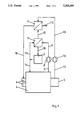
- FIG. 1 is a view schematically showing a path of a gas stream
- FIG. 2 is a simplified view of a construction of a drying apparatus in accordance with the present invention.
- FIG. 3 is a view showing a section of a nozzle box arranged in an inlet slot, on an enlarged scale
- FIG. 4 is a view showing a vertical longitudinal cross-section through a cooling tunnel of the inventive drying apparatus.
- a drying apparatus in accordance with the present invention has a first heat exchanger 1, a second heat exchanger 2, a combustion chamber 3, and a dryer 4 with a directly connectable cooling tunnel 5, as can be seen from FIG. 1.
- Nozzle boxes 6 are arranged at both sides of an inlet slot of the dryer.
- the outlet slot is also provided with nozzle boxes which, however, are not shown in FIG. 1 for the sake of simplicity of illustration.
- Waste gas with a temperature of approximately 200° C. is first aspirated from the dryer 4 by a suction blower 8 through a line 7 and then supplied to the secondary side of heat exchanger 1 through the line 9.
- the "secondary side” is a side through which the gas stream receiving the heat flows.
- the "primary side” is a side through which the gas stream giving out the heat flows.
- the waste gas pre-heated to approximately 500° C. is supplied through the line 10 to the combustion chamber 3.
- a partial stream of the pure gas which exits the combustion chamber 3 and is heated by combustion of the volatile substances to over 700° C., is supplied through the line 11 to the primary side of the heat exchanger 1. In the heat exchanger 1 it gives out a part of its heat to the inflowing waste gas and thereby cools to below 300° C.
- the pure gas is supplied through the line 12 to the primary side of the heat exchanger 2 and after cooling to 150° C. is supplied through the line 13 to a chimney. From there it is expelled into the atmosphere. A part of the hot pure gas is supplied back directly to the dryer through a direct connection provided by the line 14.
- Air is aspirated through the cooling tunnel 5 in accordance with the line 15 by a suction fan 16. It is supplied to the secondary side of the heat exchanger 2 through the line 17. There it is heated to substantially 200° C. and finally supplied to the nozzle boxes 6 through the line 18.
- FIG. 2 the parts which are similar to the parts of FIG. 1 are provided with the same reference numerals.
- the dryer 4 is composed of several fields which are arranged in a row near one another in a through-going direction identified with the arrow 19. Each field is provided in a known manner with nozzle boxes for floating guidance of the product web, with associated circulating fans and in some cases heating devices.
- the heat exchanger 1 and the combustion chamber 3 are arranged in a separate chamber 20 located above the dryer 4 and separated from the dryer by a horizontal intermediate plate.
- the internal combustion chamber has a longitudinally extending housing 21 with an end which faces the inlet slot 22 and is closed by an end wall 23.
- the internal combustion chamber has a burner 24 which is mounted in an outlet slot 25 of a neighboring end wall 26, and an ignition tube 27 which extends from the burner 24 in the housing 21 close to the end wall 23 at a lateral distance from it.
- the heat exchanger 1 arranged over the combustion chamber 3 is formed as a tubular bundle heat exchanger, and the whole unit forms the two-door passages in the secondary side.
- the second heat exchanger is composed of two units 2a and 2b which are accommodated in the dryer 4. It is also formed as a tubular bundle heat exchanger.
- the unit 2a is located above the web guidance plane 28 while the unit 2b is located below the web guidance plane.
- the units 2a and 2b are closed by tubular conduit 12a, 12b at the primary side of the heat exchanger 1 connected by conduit 13a, 13b with the chimney 29. At the secondary side they communicate through pipes 17a, 17b with the suction blower 16 which, as shown in FIG. 4, is connected at the suction side with the inner chamber of the cooling tunnel 5.
- the units 2a, 2b are also connected by tubes 18a, 18b with the nozzle boxes 6 arranged on the inlet slot and the outlet slot 22, 25 correspondingly.
- the wall of the nozzle box 6 which faces the web guidance plane 28 has a saw-tooth-shaped contour in cross-section.
- the steeper flanks 31 of the saw teeth which face the inlet slot 22 are provided with nozzle openings 32. Therefore the blow jets identified with arrows 33 are directed at an acute angle to the web guidance plane 28 toward the inlet slot 22.
- the outlet speed of the blow jets corresponds to the negative pressure in the interior of the dryer 4, the entraining of cold surrounding air through the inlet slot 22 is practically completely prevented.
- Substantially the same nozzle box 6 is arranged at the outlet slot 25.
- the required fresh air quantity is aspirated to a greater part through the cooling tunnel 5. Thereby in this region the low concentration of the post-evaporated solvent is retained. Therefore, the condensation of the cooling rollers is substantially avoided.
- nozzle boxes 34 with air cushion nozzles are arranged in the cooling tunnel 5 above and below the web guidance plane 21. They communicate through a conduit system 35 with the pressure side of the suction blower 16. Due to intensive action with returning air, a pre-cooling of the product web before it reaches the first cooling roller 36 is provided.
Abstract
Description
Claims (8)
Applications Claiming Priority (2)
| Application Number | Priority Date | Filing Date | Title |
|---|---|---|---|
| DE4226107A DE4226107A1 (en) | 1992-08-07 | 1992-08-07 | Drying plant |
| DE4226107 | 1992-08-07 |
Publications (1)
| Publication Number | Publication Date |
|---|---|
| US5333395A true US5333395A (en) | 1994-08-02 |
Family
ID=6465030
Family Applications (1)
| Application Number | Title | Priority Date | Filing Date |
|---|---|---|---|
| US08/100,576 Expired - Fee Related US5333395A (en) | 1992-08-07 | 1993-07-30 | Drying apparatus |
Country Status (4)
| Country | Link |
|---|---|
| US (1) | US5333395A (en) |
| EP (1) | EP0582077B1 (en) |
| AT (1) | ATE136359T1 (en) |
| DE (2) | DE4226107A1 (en) |
Cited By (29)
| Publication number | Priority date | Publication date | Assignee | Title |
|---|---|---|---|---|
| US5524363A (en) * | 1995-01-04 | 1996-06-11 | W. R. Grace & Co.-Conn. | In-line processing of a heated and reacting continuous sheet of material |
| US5528839A (en) * | 1995-01-18 | 1996-06-25 | W.R. Grace & Co.-Conn. | Control and arrangement of a continuous process for an industrial dryer |
| US5601789A (en) * | 1994-12-15 | 1997-02-11 | W. R. Grace & Co.-Conn. | Raw gas burner and process for burning oxygenic constituents in process gas |
| US5609833A (en) * | 1994-12-15 | 1997-03-11 | W. R. Grace & Co.-Conn. | Process and apparatus for burning oxygenic constituents in process gas |
| US5762880A (en) * | 1996-12-16 | 1998-06-09 | Megtec Systems, Inc. | Operational process and its improved control system of a secondary air burner |
| US5855476A (en) * | 1995-12-12 | 1999-01-05 | Babcock Textilmaschinen Gmbh | Device for heat treatment of continuous material webs |
| US5946819A (en) * | 1995-07-13 | 1999-09-07 | Babcock Textilmaschinen Gmbh | Continuous textile web dryer |
| WO1999057498A1 (en) * | 1998-05-07 | 1999-11-11 | Megtec Systems, Inc. | Web dryer with fully integrated regenerative heat source |
| WO2001028777A1 (en) | 1999-10-15 | 2001-04-26 | Megtec Systems, Inc. | Electrostatic assisted web cooling and remoistening device |
| EP1046874A3 (en) * | 1999-04-23 | 2001-09-12 | Heidelberger Druckmaschinen Aktiengesellschaft | Dryer with integrated cooling unit |
| US20030145481A1 (en) * | 2000-05-17 | 2003-08-07 | Zagar Steven J | Water spray web cooling apparatus for web dryer |
| US20040181967A1 (en) * | 2003-03-07 | 2004-09-23 | Fuji Photo Film Co., Ltd. | Method of manufacturing inkjet recording sheet and drying apparatus for application film |
| US20040231186A1 (en) * | 2000-09-24 | 2004-11-25 | Kolb William Blake | Coating process and apparatus |
| WO2005103591A1 (en) * | 2004-03-26 | 2005-11-03 | 3M Innovative Properties Company | Dry converting process and apparatus |
| US20060179680A1 (en) * | 2000-09-24 | 2006-08-17 | 3M Innovative Properties Company | Vapor collection method and apparatus |
| US20080282575A1 (en) * | 2005-04-13 | 2008-11-20 | Lindauer Dornier Gesellschaft Mbh | Multistage Continuous Dryer, Especially For Plate-Shaped Products |
| CN101829649A (en) * | 2010-05-26 | 2010-09-15 | 浙江华立涂装设备有限公司 | Drying oven for spraying |
| US20110000651A1 (en) * | 2007-12-13 | 2011-01-06 | Gerd Wurster | Cooling apparatus and method for cooling objects from a coating device |
| CN103575085A (en) * | 2012-07-31 | 2014-02-12 | 苏州福斯特光伏材料有限公司 | Combustion disposing, drying and heating integrated unit for organic waste gas emitted by coater |
| US20140130368A1 (en) * | 2007-02-09 | 2014-05-15 | U.S. Natural Resources, Inc, | Method and apparatus for controlling cooling temperature and pressure in wood veneer jet dryers |
| US8734615B2 (en) | 2010-11-23 | 2014-05-27 | Vits Technology Gmbh | Method and system for impregnating and drying a continuous paper web |
| US20150354120A1 (en) * | 2014-06-04 | 2015-12-10 | Teresa Catallo | Heat setter for delicate and/or sensitive knit fabrics |
| US20160251779A1 (en) * | 2013-10-18 | 2016-09-01 | Unicharm Ccorporation | Bulk recovery apparatus for nonwoven fabric and bulk recovery method for the same |
| JP2017109477A (en) * | 2015-12-15 | 2017-06-22 | 株式会社リコー | Dryer and ink jet printer system |
| EP3189974A1 (en) * | 2015-12-15 | 2017-07-12 | Ricoh Company, Ltd. | Drying device, and inkjet printer system including drying device |
| IT201700077770A1 (en) * | 2017-07-11 | 2019-01-11 | Unitech Ind S R L | DRYING FURNACE FOR FABRICS AND DRYING METHOD FOR FABRICS |
| US11040553B2 (en) | 2018-09-14 | 2021-06-22 | Canon Production Printing Holding B.V. | Method and device for drying a printed recording medium |
| US20210293482A1 (en) * | 2018-07-16 | 2021-09-23 | Wenker Gmbh & Co. Kg | Thermodynamically regulated method and thermodynamically regulated drying system for drying goods to be dried |
| US11427024B2 (en) * | 2019-03-08 | 2022-08-30 | Canon Production Printing Holding B.V. | Method and dryer system for drying a fluid mixture |
Families Citing this family (11)
| Publication number | Priority date | Publication date | Assignee | Title |
|---|---|---|---|---|
| DE19623303B4 (en) * | 1996-06-11 | 2005-08-11 | Deppe, Oliver, Dipl.-Ing. | Apparatus for drying material webs with fresh air preheating, optionally with compact circulating air blowers and guide nozzle stations |
| DE19713529A1 (en) * | 1997-04-01 | 1998-10-08 | Heidelberger Druckmasch Ag | Dryer for a material web with exhaust gas circulation |
| DE19858839B4 (en) | 1998-12-19 | 2005-02-10 | Babcock Textilmaschinen Gmbh | Method and apparatus for heat treating a continuous web by blowing steam |
| DE10010843A1 (en) * | 2000-03-06 | 2001-09-20 | Brueckner Trockentechnik Gmbh | Device and method for treating webs |
| DE10125960A1 (en) * | 2001-05-29 | 2002-12-05 | Brueckner Trockentechnik Gmbh | Assembly for drying spread wet fabric goods has an indirect heating system, for the recirculating gas to dry the material, with a cross counter-flow recuperator |
| EP1262726A1 (en) * | 2001-05-29 | 2002-12-04 | Brückner Trockentechnik GmbH & Co. KG | Apparatus for the treatment of textile webs |
| FR2958563A3 (en) * | 2010-04-13 | 2011-10-14 | Fives Stein | METHOD AND DEVICE FOR COATING METAL BANDS |
| ITFI20110076A1 (en) * | 2011-04-19 | 2012-10-20 | Unitech Textile Machinery S P A | "MACHINE FOR FABRIC TREATMENT WITH HEAT RECOVERY" |
| DE102012002865B4 (en) | 2012-02-11 | 2021-06-10 | Gogas Goch Gmbh & Co. Kg | Process for the energetic optimization of the drying process of products treated with substances containing organic solvents |
| CN116603706A (en) * | 2023-05-10 | 2023-08-18 | 新郑市吉龙包装材料有限公司 | Packaging film production line resin coating solidification auxiliary system |
| CN116518697B (en) * | 2023-07-03 | 2023-09-08 | 山东雷奥新能源有限公司 | Blast furnace drying device for producing coke |
Citations (12)
| Publication number | Priority date | Publication date | Assignee | Title |
|---|---|---|---|---|
| US3706445A (en) * | 1971-09-30 | 1972-12-19 | Granco Equipment | Fume incinerator |
| DE2412446A1 (en) * | 1974-03-15 | 1975-09-18 | Vits Maschinenbau Gmbh | Conveyor drier for goods from an offset printing press - where a heat exchanger can receive part of the flue gas containing air for reheating |
| DE2616347A1 (en) * | 1976-04-14 | 1977-10-27 | Vits Maschinenbau Gmbh | Continuous web dryer using recuperated heat - has hot and fresh air mixed near perforated plates forming air cushion |
| DE3012880A1 (en) * | 1980-04-02 | 1981-10-15 | Babcock Textilmaschinen Kg (Gmbh & Co), 2105 Seevetal | Textile web drying chamber - has additional cold air entering in counterflow with discharged hot air through heat exchanger at top |
| DE8115801U1 (en) * | 1981-10-29 | Vits-Maschinenbau Gmbh, 4018 Langenfeld | Continuous dryer | |
| DE8332567U1 (en) * | 1983-11-12 | 1985-09-26 | Vits-Maschinenbau Gmbh, 4018 Langenfeld | Continuous dryer for webs |
| US4575952A (en) * | 1981-09-18 | 1986-03-18 | M.E.G., S.A. | Hot air dryer structure |
| US4780965A (en) * | 1986-05-15 | 1988-11-01 | H. Krantz Gmbh & Co. | Method for the thermal cleaning of exhaust gases of a heat treatment apparatus |
| EP0326227A1 (en) * | 1988-01-29 | 1989-08-02 | Stork Contiweb B.V. | A drier for a web of material |
| EP0326228A1 (en) * | 1988-01-29 | 1989-08-02 | Stork Contiweb B.V. | Heating appliance |
| US5038495A (en) * | 1989-04-26 | 1991-08-13 | Stork Contiweb B.V. | Device for cooling a web of material coming out of a drier |
| EP0543439B1 (en) * | 1991-11-19 | 1996-01-31 | Stork Contiweb B.V. | Drier with improved gas management |
-
1992
- 1992-08-07 DE DE4226107A patent/DE4226107A1/en not_active Withdrawn
-
1993
- 1993-06-25 AT AT93110155T patent/ATE136359T1/en not_active IP Right Cessation
- 1993-06-25 DE DE59302094T patent/DE59302094D1/en not_active Expired - Fee Related
- 1993-06-25 EP EP93110155A patent/EP0582077B1/en not_active Expired - Lifetime
- 1993-07-30 US US08/100,576 patent/US5333395A/en not_active Expired - Fee Related
Patent Citations (12)
| Publication number | Priority date | Publication date | Assignee | Title |
|---|---|---|---|---|
| DE8115801U1 (en) * | 1981-10-29 | Vits-Maschinenbau Gmbh, 4018 Langenfeld | Continuous dryer | |
| US3706445A (en) * | 1971-09-30 | 1972-12-19 | Granco Equipment | Fume incinerator |
| DE2412446A1 (en) * | 1974-03-15 | 1975-09-18 | Vits Maschinenbau Gmbh | Conveyor drier for goods from an offset printing press - where a heat exchanger can receive part of the flue gas containing air for reheating |
| DE2616347A1 (en) * | 1976-04-14 | 1977-10-27 | Vits Maschinenbau Gmbh | Continuous web dryer using recuperated heat - has hot and fresh air mixed near perforated plates forming air cushion |
| DE3012880A1 (en) * | 1980-04-02 | 1981-10-15 | Babcock Textilmaschinen Kg (Gmbh & Co), 2105 Seevetal | Textile web drying chamber - has additional cold air entering in counterflow with discharged hot air through heat exchanger at top |
| US4575952A (en) * | 1981-09-18 | 1986-03-18 | M.E.G., S.A. | Hot air dryer structure |
| DE8332567U1 (en) * | 1983-11-12 | 1985-09-26 | Vits-Maschinenbau Gmbh, 4018 Langenfeld | Continuous dryer for webs |
| US4780965A (en) * | 1986-05-15 | 1988-11-01 | H. Krantz Gmbh & Co. | Method for the thermal cleaning of exhaust gases of a heat treatment apparatus |
| EP0326227A1 (en) * | 1988-01-29 | 1989-08-02 | Stork Contiweb B.V. | A drier for a web of material |
| EP0326228A1 (en) * | 1988-01-29 | 1989-08-02 | Stork Contiweb B.V. | Heating appliance |
| US5038495A (en) * | 1989-04-26 | 1991-08-13 | Stork Contiweb B.V. | Device for cooling a web of material coming out of a drier |
| EP0543439B1 (en) * | 1991-11-19 | 1996-01-31 | Stork Contiweb B.V. | Drier with improved gas management |
Cited By (62)
| Publication number | Priority date | Publication date | Assignee | Title |
|---|---|---|---|---|
| US5601789A (en) * | 1994-12-15 | 1997-02-11 | W. R. Grace & Co.-Conn. | Raw gas burner and process for burning oxygenic constituents in process gas |
| US5609833A (en) * | 1994-12-15 | 1997-03-11 | W. R. Grace & Co.-Conn. | Process and apparatus for burning oxygenic constituents in process gas |
| US5618173A (en) * | 1994-12-15 | 1997-04-08 | W.R. Grace & Co.-Conn. | Apparatus for burning oxygenic constituents in process gas |
| US5676536A (en) * | 1994-12-15 | 1997-10-14 | W.R. Grace & Co.-Conn. | Raw gas burner and process for burning oxygenic constituents in process gas |
| US5524363A (en) * | 1995-01-04 | 1996-06-11 | W. R. Grace & Co.-Conn. | In-line processing of a heated and reacting continuous sheet of material |
| US5579590A (en) * | 1995-01-04 | 1996-12-03 | W. R. Grace & Co.-Conn. | Apparatus for in-line processing of a heated and reacting continuous sheet of material |
| US5528839A (en) * | 1995-01-18 | 1996-06-25 | W.R. Grace & Co.-Conn. | Control and arrangement of a continuous process for an industrial dryer |
| US5555635A (en) * | 1995-01-18 | 1996-09-17 | W. R. Grace & Co.-Conn. | Control and arrangement of a continuous process for an industrial dryer |
| US5946819A (en) * | 1995-07-13 | 1999-09-07 | Babcock Textilmaschinen Gmbh | Continuous textile web dryer |
| US5855476A (en) * | 1995-12-12 | 1999-01-05 | Babcock Textilmaschinen Gmbh | Device for heat treatment of continuous material webs |
| WO1998029691A3 (en) * | 1996-12-16 | 1998-09-03 | Megtec Sys Inc | Method and apparatus for burning process gas |
| WO1998029691A2 (en) * | 1996-12-16 | 1998-07-09 | Megtec Systems, Inc. | Method and apparatus for burning process gas |
| US5762880A (en) * | 1996-12-16 | 1998-06-09 | Megtec Systems, Inc. | Operational process and its improved control system of a secondary air burner |
| WO1999057498A1 (en) * | 1998-05-07 | 1999-11-11 | Megtec Systems, Inc. | Web dryer with fully integrated regenerative heat source |
| US6321462B1 (en) | 1998-05-07 | 2001-11-27 | Megtec Systems, Inc. | Web dryer with fully integrated regenerative heat source |
| CZ299333B6 (en) * | 1998-05-07 | 2008-06-25 | Megtec Systems, Inc. | Web dryer with fully integrated regenerative heat source and drying process of a running web of material |
| EP1046874A3 (en) * | 1999-04-23 | 2001-09-12 | Heidelberger Druckmaschinen Aktiengesellschaft | Dryer with integrated cooling unit |
| US6481118B1 (en) | 1999-04-23 | 2002-11-19 | Heidelberger Druckmaschinen Ag | Dryer with integrated cooling unit and method of operation |
| WO2001028777A1 (en) | 1999-10-15 | 2001-04-26 | Megtec Systems, Inc. | Electrostatic assisted web cooling and remoistening device |
| US20030145481A1 (en) * | 2000-05-17 | 2003-08-07 | Zagar Steven J | Water spray web cooling apparatus for web dryer |
| US6775925B2 (en) * | 2000-05-17 | 2004-08-17 | Megtec Systems Inc. | Water spray web cooling apparatus for web dryer |
| US20070107254A1 (en) * | 2000-09-24 | 2007-05-17 | 3M Innovative Properties Company | Dry converting process and apparatus |
| US7918038B2 (en) | 2000-09-24 | 2011-04-05 | 3M Innovative Properties Company | Vapor collection method and apparatus |
| US20050241177A1 (en) * | 2000-09-24 | 2005-11-03 | 3M Innovative Properties Company | Coating process and apparatus |
| US7032324B2 (en) | 2000-09-24 | 2006-04-25 | 3M Innovative Properties Company | Coating process and apparatus |
| US7971370B2 (en) | 2000-09-24 | 2011-07-05 | 3M Innovative Properties Company | Vapor collection method and apparatus |
| US20060179680A1 (en) * | 2000-09-24 | 2006-08-17 | 3M Innovative Properties Company | Vapor collection method and apparatus |
| US20060191160A1 (en) * | 2000-09-24 | 2006-08-31 | 3M Innovative Properties Company | Vapor collection method and apparatus |
| US7100302B2 (en) | 2000-09-24 | 2006-09-05 | 3M Innovative Properties Company | Coating process and apparatus |
| US7143528B2 (en) | 2000-09-24 | 2006-12-05 | 3M Innovative Properties Company | Dry converting process and apparatus |
| US20040231186A1 (en) * | 2000-09-24 | 2004-11-25 | Kolb William Blake | Coating process and apparatus |
| US7918039B2 (en) | 2000-09-24 | 2011-04-05 | 3M Innovative Properties Company | Coating process and apparatus |
| US20040181967A1 (en) * | 2003-03-07 | 2004-09-23 | Fuji Photo Film Co., Ltd. | Method of manufacturing inkjet recording sheet and drying apparatus for application film |
| CN100339233C (en) * | 2003-03-07 | 2007-09-26 | 富士胶片株式会社 | Method for producing thin sheet used for ink-jet recording and drying device for coating film |
| US7080465B2 (en) * | 2003-03-07 | 2006-07-25 | Fuji Photo Film Co., Ltd. | Method of manufacturing inkjet recording sheet and drying apparatus for application film |
| JP2007530903A (en) * | 2004-03-26 | 2007-11-01 | スリーエム イノベイティブ プロパティズ カンパニー | Dry conversion process and equipment |
| KR101177953B1 (en) * | 2004-03-26 | 2012-08-28 | 쓰리엠 이노베이티브 프로퍼티즈 컴파니 | Dry converting process and apparatus |
| WO2005103591A1 (en) * | 2004-03-26 | 2005-11-03 | 3M Innovative Properties Company | Dry converting process and apparatus |
| US20080282575A1 (en) * | 2005-04-13 | 2008-11-20 | Lindauer Dornier Gesellschaft Mbh | Multistage Continuous Dryer, Especially For Plate-Shaped Products |
| US7997003B2 (en) * | 2005-04-13 | 2011-08-16 | Lindauer Dornier Gesellschaft Mbh | Multistage continuous dryer, especially for plate-shaped products |
| US9797655B2 (en) | 2007-02-09 | 2017-10-24 | Usnr, Llc | Method and apparatus for controlling cooling temperature and pressure in wood veneer jet dryers |
| US9228780B2 (en) * | 2007-02-09 | 2016-01-05 | Usnr, Llc | Method and apparatus for controlling cooling temperature and pressure in wood veneer jet dryers |
| US20140130368A1 (en) * | 2007-02-09 | 2014-05-15 | U.S. Natural Resources, Inc, | Method and apparatus for controlling cooling temperature and pressure in wood veneer jet dryers |
| US8286365B2 (en) * | 2007-12-13 | 2012-10-16 | Gerd Wurster | Cooling apparatus and method for cooling objects from a coating device |
| US20110000651A1 (en) * | 2007-12-13 | 2011-01-06 | Gerd Wurster | Cooling apparatus and method for cooling objects from a coating device |
| CN101829649A (en) * | 2010-05-26 | 2010-09-15 | 浙江华立涂装设备有限公司 | Drying oven for spraying |
| US8734615B2 (en) | 2010-11-23 | 2014-05-27 | Vits Technology Gmbh | Method and system for impregnating and drying a continuous paper web |
| CN103575085A (en) * | 2012-07-31 | 2014-02-12 | 苏州福斯特光伏材料有限公司 | Combustion disposing, drying and heating integrated unit for organic waste gas emitted by coater |
| CN103575085B (en) * | 2012-07-31 | 2016-04-20 | 苏州福斯特光伏材料有限公司 | A kind of organic exhaust gas burning process of coating machine discharge and oven dry heating combined unit |
| US9809913B2 (en) * | 2013-10-18 | 2017-11-07 | Unicharm Corporation | Bulk recovery apparatus for nonwoven fabric and bulk recovery method for the same |
| US20160251779A1 (en) * | 2013-10-18 | 2016-09-01 | Unicharm Ccorporation | Bulk recovery apparatus for nonwoven fabric and bulk recovery method for the same |
| US9714479B2 (en) * | 2014-06-04 | 2017-07-25 | Teresa Catallo | Heat setter for delicate and/or sensitive knit fabrics |
| US20150354120A1 (en) * | 2014-06-04 | 2015-12-10 | Teresa Catallo | Heat setter for delicate and/or sensitive knit fabrics |
| EP3189974A1 (en) * | 2015-12-15 | 2017-07-12 | Ricoh Company, Ltd. | Drying device, and inkjet printer system including drying device |
| JP2017109477A (en) * | 2015-12-15 | 2017-06-22 | 株式会社リコー | Dryer and ink jet printer system |
| US9884490B2 (en) | 2015-12-15 | 2018-02-06 | Ricoh Company, Ltd. | Drying device and inkjet printer system including drying device |
| US10000076B2 (en) | 2015-12-15 | 2018-06-19 | Ricoh Company, Ltd. | Drying device and inkjet printer system including drying device |
| IT201700077770A1 (en) * | 2017-07-11 | 2019-01-11 | Unitech Ind S R L | DRYING FURNACE FOR FABRICS AND DRYING METHOD FOR FABRICS |
| US20210293482A1 (en) * | 2018-07-16 | 2021-09-23 | Wenker Gmbh & Co. Kg | Thermodynamically regulated method and thermodynamically regulated drying system for drying goods to be dried |
| US11940213B2 (en) * | 2018-07-16 | 2024-03-26 | Wenker Gmbh & Co. Kg | Thermodynamically regulated method and thermodynamically regulated drying system for drying goods to be dried |
| US11040553B2 (en) | 2018-09-14 | 2021-06-22 | Canon Production Printing Holding B.V. | Method and device for drying a printed recording medium |
| US11427024B2 (en) * | 2019-03-08 | 2022-08-30 | Canon Production Printing Holding B.V. | Method and dryer system for drying a fluid mixture |
Also Published As
| Publication number | Publication date |
|---|---|
| ATE136359T1 (en) | 1996-04-15 |
| DE59302094D1 (en) | 1996-05-09 |
| DE4226107A1 (en) | 1994-02-10 |
| EP0582077A1 (en) | 1994-02-09 |
| EP0582077B1 (en) | 1996-04-03 |
Similar Documents
| Publication | Publication Date | Title |
|---|---|---|
| US5333395A (en) | Drying apparatus | |
| EP0723126B1 (en) | Control and arrangement of a continuous process for an industrial dryer | |
| US4575952A (en) | Hot air dryer structure | |
| US20070144036A1 (en) | Dryer | |
| RU2005116273A (en) | BOILER WITH FUEL BURNING WHEN USING AN OXIDATOR, ENRICHED WITH OXYGEN, TO INCREASE EFFICIENCY AND REDUCE HARMFUL EMISSIONS | |
| CN103562456B (en) | textile processing machine with heat recovery | |
| US5579590A (en) | Apparatus for in-line processing of a heated and reacting continuous sheet of material | |
| US4989348A (en) | Continuous-flow dryer for material webs, in particular offset dryer process for the thermal operation of a continuous-flow dryer | |
| JP2000343675A (en) | Drier incorporated with cooling and air-conditioning unit | |
| JPS6161006B2 (en) | ||
| JPS62211258A (en) | Device for floating and guiding web-shaped material by usinggas or liquid medium | |
| US4651680A (en) | Reduced wreath condensation boiler | |
| JPS59225277A (en) | Hot-air purifying circulating device for treating cloth | |
| JPS62191564A (en) | Fiber machine having continuous convection heat treatment part | |
| US6058626A (en) | Dryer for a material web with exhaust gas recirculation | |
| KR930011918B1 (en) | Coke dry cooling plant | |
| JPH0310870B2 (en) | ||
| US4092100A (en) | Drying oven | |
| CN218932407U (en) | Air seal structure of horizontal air supply oxidation furnace | |
| GB2079913A (en) | Web drying apparatus | |
| US3586098A (en) | Concentric tube heat exchanges | |
| US6210268B1 (en) | Air mixer for static mixing of two air streams | |
| US3071865A (en) | Web dryer | |
| RU2056588C1 (en) | Boiler plant | |
| SU1092340A1 (en) | Method of drying textile material and device for effecting same |
Legal Events
| Date | Code | Title | Description |
|---|---|---|---|
| AS | Assignment |
Owner name: VITS MASCHINENBAU GMBH Free format text: ASSIGNMENT OF ASSIGNORS INTEREST;ASSIGNOR:BULCSU, ISTVAN;REEL/FRAME:006645/0387 Effective date: 19930720 |
|
| FPAY | Fee payment |
Year of fee payment: 4 |
|
| FEPP | Fee payment procedure |
Free format text: PAYOR NUMBER ASSIGNED (ORIGINAL EVENT CODE: ASPN); ENTITY STATUS OF PATENT OWNER: LARGE ENTITY |
|
| FPAY | Fee payment |
Year of fee payment: 8 |
|
| REMI | Maintenance fee reminder mailed | ||
| LAPS | Lapse for failure to pay maintenance fees | ||
| STCH | Information on status: patent discontinuation |
Free format text: PATENT EXPIRED DUE TO NONPAYMENT OF MAINTENANCE FEES UNDER 37 CFR 1.362 |
|
| FP | Lapsed due to failure to pay maintenance fee |
Effective date: 20060802 |