US5333385A - Movable automatic sawing and clamping framework - Google Patents
Movable automatic sawing and clamping framework Download PDFInfo
- Publication number
- US5333385A US5333385A US08/054,413 US5441393A US5333385A US 5333385 A US5333385 A US 5333385A US 5441393 A US5441393 A US 5441393A US 5333385 A US5333385 A US 5333385A
- Authority
- US
- United States
- Prior art keywords
- frame portions
- pipe
- framework
- horizontal
- movable
- Prior art date
- Legal status (The legal status is an assumption and is not a legal conclusion. Google has not performed a legal analysis and makes no representation as to the accuracy of the status listed.)
- Expired - Fee Related
Links
Images


Classifications
-
- B—PERFORMING OPERATIONS; TRANSPORTING
- B23—MACHINE TOOLS; METAL-WORKING NOT OTHERWISE PROVIDED FOR
- B23Q—DETAILS, COMPONENTS, OR ACCESSORIES FOR MACHINE TOOLS, e.g. ARRANGEMENTS FOR COPYING OR CONTROLLING; MACHINE TOOLS IN GENERAL CHARACTERISED BY THE CONSTRUCTION OF PARTICULAR DETAILS OR COMPONENTS; COMBINATIONS OR ASSOCIATIONS OF METAL-WORKING MACHINES, NOT DIRECTED TO A PARTICULAR RESULT
- B23Q9/00—Arrangements for supporting or guiding portable metal-working machines or apparatus
- B23Q9/0014—Portable machines provided with or cooperating with guide means supported directly by the workpiece during action
- B23Q9/0028—Portable machines provided with or cooperating with guide means supported directly by the workpiece during action the guide means being fixed only on the machine
- B23Q9/0035—Portable machines provided with or cooperating with guide means supported directly by the workpiece during action the guide means being fixed only on the machine and being capable of guiding the tool in a circular path
-
- Y—GENERAL TAGGING OF NEW TECHNOLOGICAL DEVELOPMENTS; GENERAL TAGGING OF CROSS-SECTIONAL TECHNOLOGIES SPANNING OVER SEVERAL SECTIONS OF THE IPC; TECHNICAL SUBJECTS COVERED BY FORMER USPC CROSS-REFERENCE ART COLLECTIONS [XRACs] AND DIGESTS
- Y10—TECHNICAL SUBJECTS COVERED BY FORMER USPC
- Y10T—TECHNICAL SUBJECTS COVERED BY FORMER US CLASSIFICATION
- Y10T83/00—Cutting
- Y10T83/667—Tool carrier or guide affixed to work during cutting
- Y10T83/68—Entirely work supported
-
- Y—GENERAL TAGGING OF NEW TECHNOLOGICAL DEVELOPMENTS; GENERAL TAGGING OF CROSS-SECTIONAL TECHNOLOGIES SPANNING OVER SEVERAL SECTIONS OF THE IPC; TECHNICAL SUBJECTS COVERED BY FORMER USPC CROSS-REFERENCE ART COLLECTIONS [XRACs] AND DIGESTS
- Y10—TECHNICAL SUBJECTS COVERED BY FORMER USPC
- Y10T—TECHNICAL SUBJECTS COVERED BY FORMER US CLASSIFICATION
- Y10T83/00—Cutting
- Y10T83/768—Rotatable disc tool pair or tool and carrier
- Y10T83/7755—Carrier for rotatable tool movable during cutting
- Y10T83/7763—Tool carrier reciprocable rectilinearly
- Y10T83/7776—With means to reciprocate carrier
- Y10T83/778—And means to rotate tool
-
- Y—GENERAL TAGGING OF NEW TECHNOLOGICAL DEVELOPMENTS; GENERAL TAGGING OF CROSS-SECTIONAL TECHNOLOGIES SPANNING OVER SEVERAL SECTIONS OF THE IPC; TECHNICAL SUBJECTS COVERED BY FORMER USPC CROSS-REFERENCE ART COLLECTIONS [XRACs] AND DIGESTS
- Y10—TECHNICAL SUBJECTS COVERED BY FORMER USPC
- Y10T—TECHNICAL SUBJECTS COVERED BY FORMER US CLASSIFICATION
- Y10T83/00—Cutting
- Y10T83/869—Means to drive or to guide tool
- Y10T83/8763—Convertible from tool path to another or from implement to machine
Definitions
- the present invention relates to a movable and automatic sawing and clamping framework for wood and especially to a framework forming a movable clamping device for doing automatic or manual linear or circular cutting work on wood.
- a piece of wood cut from a log may need various additional treatment, such as sawing it to a given length as well as width or cutting a circular arc into the wood.
- FIG. 1 there is a conventional electric saw structure for sawing a piece of wood wherein an electric saw blade 11 is mounted on a working table 10.
- the saw blade extends above the plane at the table 10 and rotates.
- a workpiece 12 can then be pushed toward the blade 11 to be cut thereby.
- the workpiece 12 pushed toward the knife 11 can be cut into the shape needed.
- drawbacks in such a situation chief among them being the following: the work table 10 being fixed is inconvenient for moving to other processing places.
- the saw must be operated by a skillful workman.
- the central circular portion 13 must be cut out by making many successive tangential cuts 14, 15. This is time consuming, and the shape of the final product cannot be perfectly round.
- the principal object of the present invention is to provide a movable and automatic sawing and clamping device for wood, wherein two pipe-like frame portions are separated from each other by a suitable distance. Two sets of horizontal pieces are orthogonal to these portions and are separately provided therebetween. A clamping device can be formed between these horizontal pieces for clamping a saw tool therebetween. The whole clamping framework can be moved by means of a plurality of bottom rollers to cut the workpiece.
- a further object of the present invention is to provide a sawing and clamping device for wood, wherein the above mentioned pipe-like frame portions have a driving motor mounted thereon for driving the whole clamping framework to and from, so as to automatically cut a board.
- Another object of the present invention is to include on one end of both the pipe-like frame portions another horizontal piece orthogonal thereto.
- a center punch is provided on this piece, and a motor is provided for driving a roller provided at a location relatively far from the center punch, so as to automatically cut out a circular shape.
- Another object of the present invention is to provide a sawing and clamping device for wood, each of the pipe-like frame portions being provided with a sheet wheel and a bottom toothed roller for cooperating with a vertical toothed rail to implement vertical cutting.
- FIG. 1 is a schematic view of the structure of a conventional saw device
- FIG. 2 is a perspective view of an embodiment of the present invention
- FIG. 3 is a top view of the embodiment shown in FIG. 2;
- FIG. 4 is a partially enlarged view of the embodiment shown in FIG. 2 with a linear cutting tool installed;
- FIG. 5 is a partially exploded view showing the embodiment of FIG. 2 with an automatic driving motor installed;
- FIG. 6 is a schematic view of another embodiment of the present invention with a driving motor for cutting out a circular shape installed;
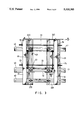
- FIG. 7 is a schematic view of the embodiment shown in FIG. 6 showing the circular movement
- FIG. 8 is a perspective view showing a part of another embodiment of the present invention adapted for vertical cutting.
- FIG. 9 is a perspective view of a stabilizing piece of the present invention.
- the present invention has two hollowed pipe-like frame portions 20, 30 separated from each other by a suitable distance.
- the vertical sides of the frame portions 20, 30 each have a slot 21, 31 extending therein almost to its entire length.
- the slots 21, 31 are parallel to each other.
- the two portions 20, 30 are pierced respectively by two transverse bolts 23, 33.
- the distance between the two portions 20, 30 is adjusted by using a plurality of nuts 24, 25, 34 and 35 to change the effective length of the bolts 23, 33.
- These two portions 20, 30 have therebetween two sets of horizontal pieces 40-41, 50-51 orthogonal thereto. These horizontal pieces all extend through the slots 21, 31 in the frame portions 20, 30. Between the horizontal pieces 40-41, 50-51, there are respectively lapping pieces 42, 52 to which vertical stop plates 43, 53 are connected respectively. Between these stop plates 43, 53 there are bolts 49, 59 provided for adjusting the distance therebetween.
- the through plate 60 At one end of the frame portions distant from the horizontal pieces 40-41, 50-51, there is another horizontal through plate 60 which has near its center position a center punch 61 capable of being pressed down to punch a center point.
- the through plate 60 has its ends extended through the slots 21, 31 in the two frame portions 20, 30, and can be moved horizontally along the length of the frame portions 20, 30.
- a small driving motor 36 is mounted on the surface of one pipe-like frame portion 30.
- a center axle of the motor 36 can drive a gear 38 via a belt 37.
- a gear 39 engaged with the gear 38 is installed on an axle rod 321 connected to a bottom roller 32 so that the rotation force can be transmitted from the motor 36 to the bottom roller 32.
- the whole clamping framework can be linear driven to and from.
- the motor 36 shown in FIG. 5 can also drive gear 360 (FIG. 6).
- the axle 361 of this gear 360 can in turn drive another touching roller 362 which is located at the end of the framework opposite to the center punch 61.
- the through plate 60 can be moved to align the position of the center punch 61 with the center line 62 of the desired circular product. Then the center punch 61 can be pressed down to punch a center point.
- the two sets of horizontal pieces 40-41, 50-51 can be moved relative to each other; therefore, the distance between the center of another sawing tool clamped therebetween and the center line 62 can be taken as a radius of the desired product. Then the rotation of the motor 36 can rotate the whole framework in a circular motion by means of the roller 362, and cut out a round piece of wood 701 as shown.
- the framework can have a scale 66 provided on a side.
- the scale 66 is used for showing distances as well as angular positions. The distance between the center of the sawing tool and the center of the desired product can be clearly seen during the movement of the through plate 60 as well as the horizontal pieces 41, 51. And certainly, the scale 66 can also be used in cutting a linear or bevel distance or angular distance.
- a bottom toothed roller 200 can be provided on the pipe-like frame portion 20. Also provided thereon is a wheel 202 which is connected with a lateral supporting axle 201.
- One of the angles pieces 204 includes toothed rail 206.
- the wheel 202 of the pipe-like frame portion 20 can be put into the opening 205, while the toothed roller 200 can be meshed with the toothed rail 206. The whole framework can thereby be used to cut in a vertical direction.
- a stabilizing piece 90 is provided for the framework of the present invention.
- the piece 90 can be connected to the top surface of a member such as the bottom base plate 220, 320.
- the piece 90 has a vertical portion 91 to which are connected two L-shaped pieces 92, 93, separated from each other, and two adjusting pieces 94, 95 with upper rollers 96, 97 mounted on the ends of the horizontal portions of the L shaped pieces 92, 93 respectively.
- the rollers 96, 97 can abut against the bottom surface of the workpiece to assure a more stable movement for cutting.
- the mobility of the sawing tool is greatly increased. It can no longer be limited to any fixed location and thus is much more convenient. And due to the automatic moving and cutting abilities of the invention, the sawing tool can make a more rapid and accurate cuts in linear or circular directions.
Landscapes
- Engineering & Computer Science (AREA)
- Mechanical Engineering (AREA)
- Sawing (AREA)
Abstract
A movable and automatic sawing and clamping device for wood, wherein two pipe-like frame portions are separated from each other by a suitable distance. Two sets of horizontal pieces are orthogonal to these portions and are separately provided therebetween. A clamping device can be formed between these horizontal pieces for clamping a saw tool therebetween. The whole clamping framework can be moved by means of a plurality of bottom rollers to cut the workpiece.
Description
The present invention relates to a movable and automatic sawing and clamping framework for wood and especially to a framework forming a movable clamping device for doing automatic or manual linear or circular cutting work on wood.
A piece of wood cut from a log may need various additional treatment, such as sawing it to a given length as well as width or cutting a circular arc into the wood.
Current art cutting machines generally have its electric sawing blade installed on a fixed working table. The wood will be pushed toward the saw for cutting.
As shown in FIG. 1, there is a conventional electric saw structure for sawing a piece of wood wherein an electric saw blade 11 is mounted on a working table 10. The saw blade extends above the plane at the table 10 and rotates. A workpiece 12 can then be pushed toward the blade 11 to be cut thereby.
The workpiece 12 pushed toward the knife 11 can be cut into the shape needed. However, there are drawbacks in such a situation, chief among them being the following: the work table 10 being fixed is inconvenient for moving to other processing places. The saw must be operated by a skillful workman. Further, when it is desired to cut from the workpiece 12 a central circular portion 13, the central circular portion 13 must be cut out by making many successive tangential cuts 14, 15. This is time consuming, and the shape of the final product cannot be perfectly round.
The principal object of the present invention is to provide a movable and automatic sawing and clamping device for wood, wherein two pipe-like frame portions are separated from each other by a suitable distance. Two sets of horizontal pieces are orthogonal to these portions and are separately provided therebetween. A clamping device can be formed between these horizontal pieces for clamping a saw tool therebetween. The whole clamping framework can be moved by means of a plurality of bottom rollers to cut the workpiece.
A further object of the present invention is to provide a sawing and clamping device for wood, wherein the above mentioned pipe-like frame portions have a driving motor mounted thereon for driving the whole clamping framework to and from, so as to automatically cut a board.
Another object of the present invention is to include on one end of both the pipe-like frame portions another horizontal piece orthogonal thereto. A center punch is provided on this piece, and a motor is provided for driving a roller provided at a location relatively far from the center punch, so as to automatically cut out a circular shape.
Another object of the present invention is to provide a sawing and clamping device for wood, each of the pipe-like frame portions being provided with a sheet wheel and a bottom toothed roller for cooperating with a vertical toothed rail to implement vertical cutting.
Other objects as well as features and effects of the present invention will be apparent to one skilled in the art from the detailed description of the preferred embodiments thereof with reference to the accompanying drawings.
FIG. 1 is a schematic view of the structure of a conventional saw device;
FIG. 2 is a perspective view of an embodiment of the present invention;
FIG. 3 is a top view of the embodiment shown in FIG. 2;
FIG. 4 is a partially enlarged view of the embodiment shown in FIG. 2 with a linear cutting tool installed;
FIG. 5 is a partially exploded view showing the embodiment of FIG. 2 with an automatic driving motor installed;
FIG. 6 is a schematic view of another embodiment of the present invention with a driving motor for cutting out a circular shape installed;
FIG. 7 is a schematic view of the embodiment shown in FIG. 6 showing the circular movement;
FIG. 8 is a perspective view showing a part of another embodiment of the present invention adapted for vertical cutting.
FIG. 9 is a perspective view of a stabilizing piece of the present invention.
Referring to FIGS. 2, and 3, the present invention has two hollowed pipe- like frame portions 20, 30 separated from each other by a suitable distance. The vertical sides of the frame portions 20, 30 each have a slot 21, 31 extending therein almost to its entire length. The slots 21, 31 are parallel to each other. On the bottom of each end of the frame portions 20, 30, there are rollers 22, 32. There are bottom base plates 220, 320, used for anchoring a plurality of bolts. The two portions 20, 30 are pierced respectively by two transverse bolts 23, 33. The distance between the two portions 20, 30 is adjusted by using a plurality of nuts 24, 25, 34 and 35 to change the effective length of the bolts 23, 33.
These two portions 20, 30 have therebetween two sets of horizontal pieces 40-41, 50-51 orthogonal thereto. These horizontal pieces all extend through the slots 21, 31 in the frame portions 20, 30. Between the horizontal pieces 40-41, 50-51, there are respectively lapping pieces 42, 52 to which vertical stop plates 43, 53 are connected respectively. Between these stop plates 43, 53 there are bolts 49, 59 provided for adjusting the distance therebetween.
At one end of the frame portions distant from the horizontal pieces 40-41, 50-51, there is another horizontal through plate 60 which has near its center position a center punch 61 capable of being pressed down to punch a center point. The through plate 60 has its ends extended through the slots 21, 31 in the two frame portions 20, 30, and can be moved horizontally along the length of the frame portions 20, 30.
As shown in FIG. 4, when the bolts 23, 33 and 49, 59 have been adjusted, the pipe- like frame portions 20, 30 and the stop plates 43, 53 form therebetween a space suitable for clamping therein various types of sawing tools 70. The one shown is a linear type sawing tool. When the whole framework is pushed to move, the rotating blade 71 provided on the saw 70 can cut the workpiece (not shown) thereunder. This is a manual type embodiment.
Referring to FIG. 5, on the surface of one pipe-like frame portion 30, a small driving motor 36 is mounted. A center axle of the motor 36 can drive a gear 38 via a belt 37. A gear 39 engaged with the gear 38 is installed on an axle rod 321 connected to a bottom roller 32 so that the rotation force can be transmitted from the motor 36 to the bottom roller 32. The whole clamping framework can be linear driven to and from.
The motor 36 shown in FIG. 5 can also drive gear 360 (FIG. 6). The axle 361 of this gear 360 can in turn drive another touching roller 362 which is located at the end of the framework opposite to the center punch 61.
Referring to FIG. 7, when it is desired to cut out a circular piece of wood, the through plate 60 can be moved to align the position of the center punch 61 with the center line 62 of the desired circular product. Then the center punch 61 can be pressed down to punch a center point. The two sets of horizontal pieces 40-41, 50-51 can be moved relative to each other; therefore, the distance between the center of another sawing tool clamped therebetween and the center line 62 can be taken as a radius of the desired product. Then the rotation of the motor 36 can rotate the whole framework in a circular motion by means of the roller 362, and cut out a round piece of wood 701 as shown.
As shown in FIGS. 6 & 7, the framework can have a scale 66 provided on a side. The scale 66 is used for showing distances as well as angular positions. The distance between the center of the sawing tool and the center of the desired product can be clearly seen during the movement of the through plate 60 as well as the horizontal pieces 41, 51. And certainly, the scale 66 can also be used in cutting a linear or bevel distance or angular distance.
In another practical embodiment of the present invention (FIG. 8), a bottom toothed roller 200 can be provided on the pipe-like frame portion 20. Also provided thereon is a wheel 202 which is connected with a lateral supporting axle 201. A rail support 203 generally attached to a wall, includes angled pieces 204 which form an upper opening 204. One of the angles pieces 204 includes toothed rail 206. The wheel 202 of the pipe-like frame portion 20 can be put into the opening 205, while the toothed roller 200 can be meshed with the toothed rail 206. The whole framework can thereby be used to cut in a vertical direction.
Referring to FIG. 9, a stabilizing piece 90 is provided for the framework of the present invention. The piece 90 can be connected to the top surface of a member such as the bottom base plate 220, 320. The piece 90 has a vertical portion 91 to which are connected two L-shaped pieces 92, 93, separated from each other, and two adjusting pieces 94, 95 with upper rollers 96, 97 mounted on the ends of the horizontal portions of the L shaped pieces 92, 93 respectively. The rollers 96, 97 can abut against the bottom surface of the workpiece to assure a more stable movement for cutting.
Due to the convenient movement of the whole framework of the present invention to any processing location at any time, the mobility of the sawing tool is greatly increased. It can no longer be limited to any fixed location and thus is much more convenient. And due to the automatic moving and cutting abilities of the invention, the sawing tool can make a more rapid and accurate cuts in linear or circular directions.
My invention is to be construed as including all modifications and variations falling within the scope of the appended claims.
Claims (8)
1. A movable and automatic sawing and clamping framework for wood comprising:
two hollow pipe-like frame portions parallel to and separated from each other by an adjustable distance, a bottom of each of the frame portions being provided with a roller and a bottom base plate;
two sets of adjustable horizontal pieces, each horizontal piece extending through slots in a respective one of said frame portions in a direction perpendicular to the frame portions and being provided with a portion between said pipe-like frame portions, a sawing tool being clamped between said horizontal pieces;
said framework being movable for cutting a workpiece; and wherein a stabilizing piece is provided adjacent to said pipe-like frame portions and is connected to top surfaces of said bottom base plates, and two separate L-shaped pieces attached to a vertical portion of said stabilizing piece, said L-shaped pieces each having a horizontal portion with an adjusting piece thereon which is provided with a roller for abutting against said workpiece.
2. The movable and automatic sawing and clamping framework for wood as claimed in claim 1 wherein:
at one end of each of said two pipe-like frame portions there is a horizontal through plate extending through the slots in the frame portions and having a center punch located at a central position of said horizontal through plate for punching a center point in said workpiece.
3. A movable and automatic sawing and clamping framework for wood comprising:
two hollow pipe-like frame portions parallel to and separated from each other by an adjustable distance, a bottom of each of the frame portions being provided with a roller and a bottom base plate;
two sets of adjustable horizontal pieces, each horizontal piece extending through slots in a respective one of said frame portions in a direction perpendicular to the frame portions and being provided with a portion between said pipe-like frame portions, a sawing tool being clamped between said horizontal pieces;
same framework being movable for cutting a workpiece; and wherein
a toothed roller is provided at the bottom of one of said pipe-like frame portions and a wheel with a lateral supporting axle is provided on a side of said one frame portion; a rail support being provided on a wall including angled pieces which form an upper opening, one of said angled pieces having a toothed rail at one side thereof for meshing with said toothed roller in a driving relationship.
4. A movable and automatic sawing and clamping framework for wood as claimed in claim 3 wherein:
a motor is provided on a surface of one of said pipe-like frame portions for driving said toothed roller at the bottom of said pipe-like frame portion through a driving device for moving the framework to cut said workpiece.
5. A movable and automatic sawing and clamping framework for wood as claimed in claim 3 wherein:
a motor is provided on a surface of one of said pipe-like frame portions for driving a touching roller located between said frame portions through a driving device for moving the framework to cut said workpiece.
6. A movable and automatic sawing and clamping framework for wood comprising:
two hollow pipe-like frame portions parallel to and separated from each other by an adjustable distance, a bottom of each of the frame portions being provided with a roller and a bottom base plate;
two sets of adjustable horizontal pieces, each horizontal piece extending through slots in a respective one of said frame portions in a direction perpendicular to the frame portions and being provided with a portion between said pipe-like frame portions, a sawing tool being clamped between said horizontal pieces;
said framework being movable for cutting a workpiece; and wherein at one end of each of said two pipe-like frame portions there is a horizontal through plate extending through the slots in the frame portions and having a center punch located at a central position of said horizontal through plate for punching a center point in said workpiece, and wherein
a toothed roller is provided at the bottom of one of said pipe-like frame portions and a wheel with a lateral supporting axle is provided on a side of said one frame portion; a rail support being provided on a wall including angled pieces which form an upper opening, one of said angled pieces having a toothed rail at one side thereof for meshing with said toothed roller in a driving relationship.
7. A movable and automatic sawing and clamping framework for wood as claimed in claim 6 wherein:
a motor is provided on a surface of one of said pipe-like frame portions for driving said toothed roller at the bottom of said pipe-like frame portion through a driving device for moving the framework for cut said workpiece.
8. A movable and automatic sawing and clamping framework for wood as claimed in claim 6 wherein:
a motor is provided on a surface of one of said pipe-like frame portions for driving a touching roller located between said frame portions through a driving device for moving the framework to cut said workpiece.
Priority Applications (1)
| Application Number | Priority Date | Filing Date | Title |
|---|---|---|---|
| US08/054,413 US5333385A (en) | 1993-04-27 | 1993-04-27 | Movable automatic sawing and clamping framework |
Applications Claiming Priority (1)
| Application Number | Priority Date | Filing Date | Title |
|---|---|---|---|
| US08/054,413 US5333385A (en) | 1993-04-27 | 1993-04-27 | Movable automatic sawing and clamping framework |
Publications (1)
| Publication Number | Publication Date |
|---|---|
| US5333385A true US5333385A (en) | 1994-08-02 |
Family
ID=21990900
Family Applications (1)
| Application Number | Title | Priority Date | Filing Date |
|---|---|---|---|
| US08/054,413 Expired - Fee Related US5333385A (en) | 1993-04-27 | 1993-04-27 | Movable automatic sawing and clamping framework |
Country Status (1)
| Country | Link |
|---|---|
| US (1) | US5333385A (en) |
Cited By (14)
| Publication number | Priority date | Publication date | Assignee | Title |
|---|---|---|---|---|
| US6412179B1 (en) * | 2000-08-22 | 2002-07-02 | Mathias Am Ende | Cutting guide apparatus for guiding portable power cutting tools |
| US6488256B1 (en) * | 2000-09-25 | 2002-12-03 | Wen-Chi Chang | Adjustable mounting bracket for a power hand tool |
| US6591728B1 (en) * | 2000-01-05 | 2003-07-15 | David G. Grondahl | Clamping power tool guide with integral measurement tool |
| US20060027288A1 (en) * | 2004-08-09 | 2006-02-09 | Alan Williams | Apparatus and method for cutting a lap joint |
| US20060086418A1 (en) * | 2004-08-09 | 2006-04-27 | Alan Williams | Apparatus and method for cutting workpiece |
| US7059225B1 (en) * | 2002-07-22 | 2006-06-13 | Roberto Jaime Rabell | Holder device for attaching a circular saw to a T square |
| US20090049972A1 (en) * | 2007-07-26 | 2009-02-26 | Black & Decker Inc. | Footplate |
| US20140047967A1 (en) * | 2012-07-15 | 2014-02-20 | Dino Makropoulos | Saw Base for Providing Straight And Bevel Cuts Having A Common Cut Line |
| US20140260849A1 (en) * | 2013-03-14 | 2014-09-18 | General Electric Company | Tool and method for scarfing a rotor blade segment |
| US20150313380A1 (en) * | 2014-05-01 | 2015-11-05 | Mettler-Toledo, LLC | Adjustable scanner mounting assembly and method |
| CN111516150A (en) * | 2020-05-28 | 2020-08-11 | 周羽鹏 | Concrete cutting machine |
| US10961982B2 (en) | 2017-11-07 | 2021-03-30 | General Electric Company | Method of joining blade sections using thermoplastics |
| US20230018046A1 (en) * | 2015-11-25 | 2023-01-19 | Flo-Water, Llc | Water inlet protection system |
| US12285919B2 (en) | 2020-12-30 | 2025-04-29 | Lm Wind Power Us Technology Aps | Method of joining segments of a composite component |
Citations (8)
| Publication number | Priority date | Publication date | Assignee | Title |
|---|---|---|---|---|
| US2770265A (en) * | 1953-07-28 | 1956-11-13 | Leon J Pollock | Combination guide and portable support for power saws |
| US4023273A (en) * | 1976-07-26 | 1977-05-17 | Treleaven Thomas R | Sabre saw guide assembly |
| US4397207A (en) * | 1980-02-25 | 1983-08-09 | Dalton Isaac | Sheet metal cutting device for arcs and circles |
| US4621427A (en) * | 1984-04-13 | 1986-11-11 | Black & Decker Overseas Ag | Guide device for a mobile working tool |
| US5016354A (en) * | 1989-08-21 | 1991-05-21 | Baine James R | Circular cutting device |
| US5033347A (en) * | 1989-08-25 | 1991-07-23 | Hillestad Tollief O | Boiler tube cutting apparatus |
| US5165317A (en) * | 1987-12-24 | 1992-11-24 | Findlay Brian D | Multi-use apparatus for the control of portable power tools |
| US5203389A (en) * | 1992-11-06 | 1993-04-20 | Goodwin Edward J | Precision wood-joint making fixture apparatus and method of use with a router |
-
1993
- 1993-04-27 US US08/054,413 patent/US5333385A/en not_active Expired - Fee Related
Patent Citations (8)
| Publication number | Priority date | Publication date | Assignee | Title |
|---|---|---|---|---|
| US2770265A (en) * | 1953-07-28 | 1956-11-13 | Leon J Pollock | Combination guide and portable support for power saws |
| US4023273A (en) * | 1976-07-26 | 1977-05-17 | Treleaven Thomas R | Sabre saw guide assembly |
| US4397207A (en) * | 1980-02-25 | 1983-08-09 | Dalton Isaac | Sheet metal cutting device for arcs and circles |
| US4621427A (en) * | 1984-04-13 | 1986-11-11 | Black & Decker Overseas Ag | Guide device for a mobile working tool |
| US5165317A (en) * | 1987-12-24 | 1992-11-24 | Findlay Brian D | Multi-use apparatus for the control of portable power tools |
| US5016354A (en) * | 1989-08-21 | 1991-05-21 | Baine James R | Circular cutting device |
| US5033347A (en) * | 1989-08-25 | 1991-07-23 | Hillestad Tollief O | Boiler tube cutting apparatus |
| US5203389A (en) * | 1992-11-06 | 1993-04-20 | Goodwin Edward J | Precision wood-joint making fixture apparatus and method of use with a router |
Cited By (19)
| Publication number | Priority date | Publication date | Assignee | Title |
|---|---|---|---|---|
| US6591728B1 (en) * | 2000-01-05 | 2003-07-15 | David G. Grondahl | Clamping power tool guide with integral measurement tool |
| US6412179B1 (en) * | 2000-08-22 | 2002-07-02 | Mathias Am Ende | Cutting guide apparatus for guiding portable power cutting tools |
| US6488256B1 (en) * | 2000-09-25 | 2002-12-03 | Wen-Chi Chang | Adjustable mounting bracket for a power hand tool |
| US7059225B1 (en) * | 2002-07-22 | 2006-06-13 | Roberto Jaime Rabell | Holder device for attaching a circular saw to a T square |
| US7497238B2 (en) * | 2004-08-09 | 2009-03-03 | Alan Williams | Apparatus and method for cutting workpiece |
| US20060027288A1 (en) * | 2004-08-09 | 2006-02-09 | Alan Williams | Apparatus and method for cutting a lap joint |
| US20060086418A1 (en) * | 2004-08-09 | 2006-04-27 | Alan Williams | Apparatus and method for cutting workpiece |
| US7856723B2 (en) * | 2007-07-26 | 2010-12-28 | Black & Decker Inc. | Footplate |
| US20090049972A1 (en) * | 2007-07-26 | 2009-02-26 | Black & Decker Inc. | Footplate |
| US20140047967A1 (en) * | 2012-07-15 | 2014-02-20 | Dino Makropoulos | Saw Base for Providing Straight And Bevel Cuts Having A Common Cut Line |
| US20140260849A1 (en) * | 2013-03-14 | 2014-09-18 | General Electric Company | Tool and method for scarfing a rotor blade segment |
| US9683548B2 (en) * | 2013-03-14 | 2017-06-20 | General Electric Company | Tool and method for scarfing a rotor blade segment |
| US20150313380A1 (en) * | 2014-05-01 | 2015-11-05 | Mettler-Toledo, LLC | Adjustable scanner mounting assembly and method |
| US10188225B2 (en) * | 2014-05-01 | 2019-01-29 | Mettler-Toledo, LLC | Adjustable scanner mounting assembly and method |
| US20230018046A1 (en) * | 2015-11-25 | 2023-01-19 | Flo-Water, Llc | Water inlet protection system |
| US12134886B2 (en) * | 2015-11-25 | 2024-11-05 | Flo-Water, Llc | Water inlet protection system |
| US10961982B2 (en) | 2017-11-07 | 2021-03-30 | General Electric Company | Method of joining blade sections using thermoplastics |
| CN111516150A (en) * | 2020-05-28 | 2020-08-11 | 周羽鹏 | Concrete cutting machine |
| US12285919B2 (en) | 2020-12-30 | 2025-04-29 | Lm Wind Power Us Technology Aps | Method of joining segments of a composite component |
Similar Documents
| Publication | Publication Date | Title |
|---|---|---|
| US5333385A (en) | Movable automatic sawing and clamping framework | |
| US2601878A (en) | Table saw with part of the table swingably and laterally adjustable | |
| US4320678A (en) | Portable power tool accessory table | |
| CN209831886U (en) | Sawing machine for cutting wood board | |
| US5408909A (en) | Arrangement for measuring and cutting a workpiece | |
| US4694722A (en) | Apparatus for scoring and cutting wallboard and the like | |
| US4777854A (en) | Dimensional cutting tool for wood | |
| US4741370A (en) | Router tool | |
| US3915038A (en) | Fiber board cutter | |
| US4409875A (en) | Apparatus for manufacturing an integral wooden angle bar | |
| SU435606A1 (en) | THE DEVICE FOR REMOVAL OF WEALTHS, FOR EXAMPLE, Plywood FROM FACED PREPARATIONS | |
| GB2208071A (en) | Power tool table | |
| US2568957A (en) | Rotary portable saw support mitering machine | |
| US5484003A (en) | Chop saw table | |
| JPS5832889Y2 (en) | Bannoumokukouki | |
| US5129436A (en) | Apparatus for forming shaped edges | |
| JPS6420920A (en) | Vertical band sawing machine | |
| KR100318062B1 (en) | A band sawing machine for a steel cutting | |
| US3692075A (en) | Routing device with movable routing tool | |
| US4228710A (en) | Cut-off saw attachment for machine tool | |
| CN218593202U (en) | Wood board slitting equipment for wood processing | |
| GB2056908A (en) | A feed and delivery of logs between two saws | |
| JP2678113B2 (en) | Material guide device for material cutting machine | |
| RU2013200C1 (en) | Combined wood-working machine tool | |
| US20070074614A1 (en) | Light duty, long axis, portable, suspension cutter |
Legal Events
| Date | Code | Title | Description |
|---|---|---|---|
| LAPS | Lapse for failure to pay maintenance fees | ||
| FP | Lapsed due to failure to pay maintenance fee |
Effective date: 19980802 |
|
| STCH | Information on status: patent discontinuation |
Free format text: PATENT EXPIRED DUE TO NONPAYMENT OF MAINTENANCE FEES UNDER 37 CFR 1.362 |