US533271A - Ash chute siftee - Google Patents
Ash chute siftee Download PDFInfo
- Publication number
- US533271A US533271A US533271DA US533271A US 533271 A US533271 A US 533271A US 533271D A US533271D A US 533271DA US 533271 A US533271 A US 533271A
- Authority
- US
- United States
- Prior art keywords
- ash
- receiver
- sifter
- chute
- damper
- Prior art date
- Legal status (The legal status is an assumption and is not a legal conclusion. Google has not performed a legal analysis and makes no representation as to the accuracy of the status listed.)
- Expired - Lifetime
Links
- 239000002956 ash Substances 0.000 description 69
- 235000002918 Fraxinus excelsior Nutrition 0.000 description 16
- 239000003245 coal Substances 0.000 description 14
- 238000010276 construction Methods 0.000 description 9
- 238000005192 partition Methods 0.000 description 5
- XEEYBQQBJWHFJM-UHFFFAOYSA-N Iron Chemical compound [Fe] XEEYBQQBJWHFJM-UHFFFAOYSA-N 0.000 description 2
- 230000000717 retained effect Effects 0.000 description 2
- ATJFFYVFTNAWJD-UHFFFAOYSA-N Tin Chemical compound [Sn] ATJFFYVFTNAWJD-UHFFFAOYSA-N 0.000 description 1
- 239000004020 conductor Substances 0.000 description 1
- 229910052742 iron Inorganic materials 0.000 description 1
Images

Classifications
-
- F—MECHANICAL ENGINEERING; LIGHTING; HEATING; WEAPONS; BLASTING
- F24—HEATING; RANGES; VENTILATING
- F24B—DOMESTIC STOVES OR RANGES FOR SOLID FUELS; IMPLEMENTS FOR USE IN CONNECTION WITH STOVES OR RANGES
- F24B15/00—Implements for use in connection with stoves or ranges
- F24B15/007—Ash-sifters
-
- B—PERFORMING OPERATIONS; TRANSPORTING
- B07—SEPARATING SOLIDS FROM SOLIDS; SORTING
- B07B—SEPARATING SOLIDS FROM SOLIDS BY SIEVING, SCREENING, SIFTING OR BY USING GAS CURRENTS; SEPARATING BY OTHER DRY METHODS APPLICABLE TO BULK MATERIAL, e.g. LOOSE ARTICLES FIT TO BE HANDLED LIKE BULK MATERIAL
- B07B1/00—Sieving, screening, sifting, or sorting solid materials using networks, gratings, grids, or the like
- B07B1/46—Constructional details of screens in general; Cleaning or heating of screens
Definitions
- My invention relates to ash chute sitters, and more particularly to the combination with the ash box or receiver of an ash chute, of ordinary construct-ion, usually located at the rear of buildings of two or more stories in height to receive ashes and convey the same into a receptacle at the lower end of the chute, of an ash sifter, located in the ash receiver of the chute, at each story of the building, for the purpose of sifting the ashes and separating them from the coal, and causing the ashes to pass down into and through the ash chute into a receptacle at the lower end thereof," and the coal to pass out of the ash receiver into a coal hod or receptacle placed to receive it.
- the obj eat of myinvention is to provide an eflicient mechanism combined with the ash receiver of the chute, of ordinary construction, by means of which ashes may be sifted, and the coal separated and saved, and caused to pass into a receptacle placed to receive it, while the ashes pass down into and through the ash chute in the ordinary way, and fall into the receptacle at the lower end thereof.
- Myinvention consists in certain novel features of construction of an ash sifter, combined with the ash receiver of an ash chute,
- Fig.2 is a cross section on line 2, 2
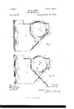
- Fig.3 isacentral verticalsection of the parts shown in Fig. 1, and Fig. 4 corresponds to Fig. 8, but Shows the damper at- .tachment open, to cause the coal to pass out of the ash receiver into a receptacle, not shown, placed to receive it.
- 1 is a portion of the main chute or conductor, of circular shape, and made of tin or galvanized iron, in the ordinary way.
- ash receiver or box is the ash receiver or box, attached to the chute 1, and forming a part thereof, in the ordinary way.
- my ash sifter mechanism which consists of a rotary ash sifter 3, of cylindrical shape, and preferably made of wire netting, and supported and adapted to revolve within the ash receiver 2 in the upper portion thereof, on a central shaft 4,;journaled in the sides of the ash receiver 2, and provided with a handle 5, to revolve the same.
- a latch 6, pivoted on a pin 7, is adapted to engage a notched ear 5 on the handle 5, to hold the sifter 3 in the position shown in Figs. 1 and 2,
- the removable slidecover 8 is retained in place by groovedstrips 9, extending lengthwise of and securedto the ash sifter 3, as shown in Fig. 2, and said cover 8 is adapted to be drawn from the ash sifter 3 to allow access to the same, to pour the ashes into the sifter, and also to discharge the coal from the sifter, after the ashes have been sifted out.
- a hinged cover may be used if preferred.
- the top of the sifter projects above the top of the receiver far enough to permit the cover being moved endwise in the grooves without coming in contact with the sides of the receiver, and without the necessity of cutting a hole in the side of the receiver, as would be the case if the top of the sifter were even with or below the top of the receiver.
- the top of the ash receiver 2- is provided with a hinged cover 10, which fits over and incloses the top of the ash sifter 3.
- a partition or division 11 secured within the ash receiver 2, and extending from side to side thereof, as shown in Fig. 2, and adapted to inclose the rear portion of the ash sifter 3, so as to form a separate box or inclosure for the ash sifter.
- the partition 11 is cut away at its lower end, or does not extend to the outer front side of the ash receiver 2, so that an opening 12 is left, see Fig. 3, through which the ashes pass down the inclined side of the ash receiver 2 into the ash chute 1.
- a damper attachment which is preferably made separate from the ash receiver 2, and is adapted to be combined with any ash receiver, and consists of a frame 13, which is adapted to fit on to and be secured to an opening cut in the front portion or side of the ash receiver 2.
- a damper 15 In the frame 13, on a pin 14, is pivoted a damper 15, the upper end of which, 15, is preferably made heavier than the lower end 15" thereof, and preferably of concave shape on the inside, to cause the ashes falling thereon to pass down along the central portion of the ash receiver 2.
- the damper 15 is retained in position by a button 16, pivoted on the frame 13, as shown in Fig. 3.
- the damper 15 When the damper 15 is in the position shown in Fig. 3, and the ash sifter3 is rotated,the ashes will fall on to said damper, and pass down through the opening 12 into the chute.
- the button 16 is turned to release the damper 15, and the weight of the end 15' thereof will cause the damper to rotate outwardly on its pivot joint, and cause the opposite end 15" thereof to strike and bear against the inclined portion of the division ll, and hold the damper in this position. See Fig. 4.
- the sifter3 is then revolved so that the slide 8 will be at the lower side thereof, and when removed, as shown in Fig. the coal will fall out of the sifter on to the damper 15, and be carried into a coal hod or other receptacle placed at the lower outer end of said damper.
- the concave shape of the end 15' of the damper 15, Will prevent the coal from dropping 0d the edges thereof.
- the concavity in the damper By extending the concavity in the damper from the end substantially to the pivotal point, which is located at the lower end of the opening 12 and in a line with the inclined portion of the partition 11, the ashes that fall on any portion ofthe damper within the opening will be thrown toward the center, and all the coal falling on the flat portion, as shown in Fig. 4, will be deflected toward the center, whereas if inclined cleats were used instead of a concavity, any ashes falling above the cleats when the damper is closed could not pass down into the chute.
- the damper is moved back into the position shown in Fig. 3, and the sifter is rotated, so that the slide 8 will be at the top thereof, and the sifter is ready to be used again.
- an ash chute sifter the combination, with a receiver, the front of which is provided with an opening, a partition in the receiver, the lower end of which is provided with an inclined portion in line with the lower end of the opening, a frame in the opening, a damper in said opening one end of which is concaved and covers the opening, and the other end projects into the receiver and is adapted to be moved into engagement with the inclined portion of the partition, and a sifter within the receiver above the damper, substantially as set forth.
Landscapes
- Engineering & Computer Science (AREA)
- Chemical & Material Sciences (AREA)
- Combustion & Propulsion (AREA)
- Mechanical Engineering (AREA)
- General Engineering & Computer Science (AREA)
- Combined Means For Separation Of Solids (AREA)
Description
(No Model.)
, 2 Sheets-Sheet 1'. H.E.BUGK. ASH GHUTESIFTER.
Patented Jan. 29. 1895.
- nmmuw "m: News Ps'rsns co. PHOTO-UTHO. WASHMOTON, n. c.
(No Model.) 2 Sheets-Sheet 2'. H. E. BUCK.
ASH GHUTE SIFTER.
No. 533,271. v Patented Jan. 29, 1895.
Units rnrns HELON E. BUCK, OF VVOROESTER, MASSACHUSETTS, ASSIGNOR TO GEORGE .F. BAR-NARD, OF SAME PLACE.
ASH-CHUTE SIFTER.
SPECIFICATION forming part of Letters Patent No. 533,271, dated January 29, 1 895.
Application filed October 28,1893. Serial lie-489,377. (No model.)
To aZZ whom 722; may concern.-
Be it known that LHELON E. BUCK, a citizen of the United States, residing at Worcester, in the county of .Worcester and State of Massachusetts, have invented certain new and useful Improvements in Ash-Chute Sifters; and I do hereby declare that the following is a full, clear, and exact description thereof, which, in connection with the drawings making a part of this specification, will enable others skilled in the art to which my invention belongs to make and use the same.
My invention relates to ash chute sitters, and more particularly to the combination with the ash box or receiver of an ash chute, of ordinary construct-ion, usually located at the rear of buildings of two or more stories in height to receive ashes and convey the same into a receptacle at the lower end of the chute, of an ash sifter, located in the ash receiver of the chute, at each story of the building, for the purpose of sifting the ashes and separating them from the coal, and causing the ashes to pass down into and through the ash chute into a receptacle at the lower end thereof," and the coal to pass out of the ash receiver into a coal hod or receptacle placed to receive it.
In the ordinary construction of ash chutes there is no provision for sifting the ashes so as to separate any coal that may bemingled with the ashes, and the ordinary practice is to pour the contents of the ash pan or coal hod into the ash receiver, connected with the ash chute, and located at each floor of the building, and allow all of the content to pass into and down the ash chute into the receptacle at the lower end thereof.
The obj eat of myinvention is to provide an eflicient mechanism combined with the ash receiver of the chute, of ordinary construction, by means of which ashes may be sifted, and the coal separated and saved, and caused to pass into a receptacle placed to receive it, while the ashes pass down into and through the ash chute in the ordinary way, and fall into the receptacle at the lower end thereof.
Myinvention consists in certain novel features of construction of an ash sifter, combined with the ash receiver of an ash chute,
of ordinary construction, into which the ashes 'a portion of an ash chute, and a side view of the ash receiver or box attached thereto, with my ash sifter mechanism combined therewith. Fig.2 is a cross section on line 2, 2,
Fig. 1, looking in the direction of arrow at,
same figure. Fig.3isacentral verticalsection of the parts shown in Fig. 1, and Fig. 4 corresponds to Fig. 8, but Shows the damper at- .tachment open, to cause the coal to pass out of the ash receiver into a receptacle, not shown, placed to receive it.
In the accompanying drawings, 1 is a portion of the main chute or conductor, of circular shape, and made of tin or galvanized iron, in the ordinary way.
2 is the ash receiver or box, attached to the chute 1, and forming a part thereof, in the ordinary way. With the ash receiver or box 2 is combined my ash sifter mechanism, which consists of a rotary ash sifter 3, of cylindrical shape, and preferably made of wire netting, and supported and adapted to revolve within the ash receiver 2 in the upper portion thereof, on a central shaft 4,;journaled in the sides of the ash receiver 2, and provided with a handle 5, to revolve the same. A latch 6, pivoted on a pin 7, is adapted to engage a notched ear 5 on the handle 5, to hold the sifter 3 in the position shown in Figs. 1 and 2,
with the slide cover 8 of the ash sifter 3 at the top of the sifter. The removable slidecover 8 is retained in place by groovedstrips 9, extending lengthwise of and securedto the ash sifter 3, as shown in Fig. 2, and said cover 8 is adapted to be drawn from the ash sifter 3 to allow access to the same, to pour the ashes into the sifter, and also to discharge the coal from the sifter, after the ashes have been sifted out.
Instead of a slide cover 8, a hinged cover may be used if preferred.
The top of the sifter projects above the top of the receiver far enough to permit the cover being moved endwise in the grooves without coming in contact with the sides of the receiver, and without the necessity of cutting a hole in the side of the receiver, as would be the case if the top of the sifter were even with or below the top of the receiver.
The top of the ash receiver 2-is provided with a hinged cover 10, which fits over and incloses the top of the ash sifter 3.
In connection with the rotary ash sifter 3is preferably employed a partition or division 11, secured within the ash receiver 2, and extending from side to side thereof, as shown in Fig. 2, and adapted to inclose the rear portion of the ash sifter 3, so as to form a separate box or inclosure for the ash sifter. The partition 11 is cut away at its lower end, or does not extend to the outer front side of the ash receiver 2, so that an opening 12 is left, see Fig. 3, through which the ashes pass down the inclined side of the ash receiver 2 into the ash chute 1.
Combined with the front portion or edge of the ash receiver 2 is a damper attachment, which is preferably made separate from the ash receiver 2, and is adapted to be combined with any ash receiver, and consists of a frame 13, which is adapted to fit on to and be secured to an opening cut in the front portion or side of the ash receiver 2.
In the frame 13, on a pin 14, is pivoted a damper 15, the upper end of which, 15, is preferably made heavier than the lower end 15" thereof, and preferably of concave shape on the inside, to cause the ashes falling thereon to pass down along the central portion of the ash receiver 2. The damper 15 is retained in position by a button 16, pivoted on the frame 13, as shown in Fig. 3. When the damper 15 is in the position shown in Fig. 3, and the ash sifter3 is rotated,the ashes will fall on to said damper, and pass down through the opening 12 into the chute. After the ashes have been sifted, and only the coal remains in the sifter, the button 16 is turned to release the damper 15, and the weight of the end 15' thereof will cause the damper to rotate outwardly on its pivot joint, and cause the opposite end 15" thereof to strike and bear against the inclined portion of the division ll, and hold the damper in this position. See Fig. 4. The sifter3 is then revolved so that the slide 8 will be at the lower side thereof, and when removed, as shown in Fig. the coal will fall out of the sifter on to the damper 15, and be carried into a coal hod or other receptacle placed at the lower outer end of said damper. The concave shape of the end 15' of the damper 15, Will prevent the coal from dropping 0d the edges thereof. By extending the concavity in the damper from the end substantially to the pivotal point, which is located at the lower end of the opening 12 and in a line with the inclined portion of the partition 11, the ashes that fall on any portion ofthe damper within the opening will be thrown toward the center, and all the coal falling on the flat portion, as shown in Fig. 4, will be deflected toward the center, whereas if inclined cleats were used instead of a concavity, any ashes falling above the cleats when the damper is closed could not pass down into the chute. After the coal has been dumped out of the sifter, the damper is moved back into the position shown in Fig. 3, and the sifter is rotated, so that the slide 8 will be at the top thereof, and the sifter is ready to be used again.
The advantages of my improved ash sifter mechanism, adapted to be combined with the ash receiver of an ash chute of ordinary construction, will be readily appreciated by those skilled in the art. It is of very simple construction and operation, and adapted to be applied to, and combined with any ash receiver of an ash chute already in use, and of ordinary construction, it only being necessary to insert the division 11 in the receiver, and out out the front portion or side of the receiver, and insert the damper attachment.
It will be understood that the details of construction of some of the parts of my ash sifter mechanism may be varied from what is shown and described, if desired.
Having thus described my invention, what I claim as new, and desire to secure by Letters Patent, is-
In an ash chute sifter, the combination, with a receiver, the front of which is provided with an opening, a partition in the receiver, the lower end of which is provided with an inclined portion in line with the lower end of the opening, a frame in the opening, a damper in said opening one end of which is concaved and covers the opening, and the other end projects into the receiver and is adapted to be moved into engagement with the inclined portion of the partition, and a sifter within the receiver above the damper, substantially as set forth.
HELON E. BUCK. Witnesses:
KATIE FARRELL, JOHN C. DEWEY.
Publications (1)
| Publication Number | Publication Date |
|---|---|
| US533271A true US533271A (en) | 1895-01-29 |
Family
ID=2602036
Family Applications (1)
| Application Number | Title | Priority Date | Filing Date |
|---|---|---|---|
| US533271D Expired - Lifetime US533271A (en) | Ash chute siftee |
Country Status (1)
| Country | Link |
|---|---|
| US (1) | US533271A (en) |
-
0
- US US533271D patent/US533271A/en not_active Expired - Lifetime
Similar Documents
| Publication | Publication Date | Title |
|---|---|---|
| US533271A (en) | Ash chute siftee | |
| US558170A (en) | Ash-sifter | |
| US1179875A (en) | Grain separator and grader. | |
| US387034A (en) | Ash-sifter | |
| US1159962A (en) | Separator. | |
| US550181A (en) | Andrew b | |
| US730204A (en) | Attached ash-sifter. | |
| US234033A (en) | Ash-sifter | |
| US111126A (en) | Improvement in ash-screens | |
| US235061A (en) | peters | |
| US147301A (en) | Improvement in machines for assorting potatoes | |
| US676725A (en) | Ash-sifter. | |
| US1485396A (en) | Sifter | |
| US303916A (en) | John beown | |
| US603704A (en) | Ash-sifter | |
| US456036A (en) | Nathaniel hunt and francis c | |
| US369223A (en) | William a | |
| US451257A (en) | Ash-sifter | |
| US202157A (en) | Improvement in ash-sifters | |
| US1268092A (en) | Ash-sifter. | |
| US399862A (en) | Sifter | |
| US297737A (en) | Ash-sifter | |
| US556347A (en) | Ash-sieve | |
| US1125482A (en) | Ash-sifter. | |
| US284847A (en) | hewsobt |