US5330137A - Apparatus and method for mounting an electrical box between studs in a wall - Google Patents
Apparatus and method for mounting an electrical box between studs in a wall Download PDFInfo
- Publication number
- US5330137A US5330137A US08/000,189 US18993A US5330137A US 5330137 A US5330137 A US 5330137A US 18993 A US18993 A US 18993A US 5330137 A US5330137 A US 5330137A
- Authority
- US
- United States
- Prior art keywords
- box
- faceplate
- frame
- electrical box
- bracket
- Prior art date
- Legal status (The legal status is an assumption and is not a legal conclusion. Google has not performed a legal analysis and makes no representation as to the accuracy of the status listed.)
- Expired - Lifetime
Links
Images


Classifications
-
- H—ELECTRICITY
- H02—GENERATION; CONVERSION OR DISTRIBUTION OF ELECTRIC POWER
- H02G—INSTALLATION OF ELECTRIC CABLES OR LINES, OR OF COMBINED OPTICAL AND ELECTRIC CABLES OR LINES
- H02G3/00—Installations of electric cables or lines or protective tubing therefor in or on buildings, equivalent structures or vehicles
- H02G3/02—Details
- H02G3/08—Distribution boxes; Connection or junction boxes
- H02G3/12—Distribution boxes; Connection or junction boxes for flush mounting
- H02G3/123—Distribution boxes; Connection or junction boxes for flush mounting in thin walls
- H02G3/125—Distribution boxes; Connection or junction boxes for flush mounting in thin walls with supporting bar extending between two separate studs of a wall frame
-
- H—ELECTRICITY
- H02—GENERATION; CONVERSION OR DISTRIBUTION OF ELECTRIC POWER
- H02B—BOARDS, SUBSTATIONS OR SWITCHING ARRANGEMENTS FOR THE SUPPLY OR DISTRIBUTION OF ELECTRIC POWER
- H02B1/00—Frameworks, boards, panels, desks, casings; Details of substations or switching arrangements
- H02B1/015—Boards, panels, desks; Parts thereof or accessories therefor
-
- Y—GENERAL TAGGING OF NEW TECHNOLOGICAL DEVELOPMENTS; GENERAL TAGGING OF CROSS-SECTIONAL TECHNOLOGIES SPANNING OVER SEVERAL SECTIONS OF THE IPC; TECHNICAL SUBJECTS COVERED BY FORMER USPC CROSS-REFERENCE ART COLLECTIONS [XRACs] AND DIGESTS
- Y10—TECHNICAL SUBJECTS COVERED BY FORMER USPC
- Y10S—TECHNICAL SUBJECTS COVERED BY FORMER USPC CROSS-REFERENCE ART COLLECTIONS [XRACs] AND DIGESTS
- Y10S248/00—Supports
- Y10S248/906—Electrical outlet box support
Definitions
- This invention relates to mechanical brackets for mounting electrical boxes between studs in a wall and more specifically to a mounting bracket which allows boxes having different depths to be mounted on the same bracket.
- Brackets for mounting electrical boxes between wall studs are used on a daily basis in the construction industry. These brackets allow the builder to conveniently traverse the space between the studs and mount an electrical box at any location he chooses.
- a typical prior art bracket is disclosed in U.S. Pat. No. 4,967,990 issued to Rinderer. With reference to FIGS. 1 and 2 in Rinderer, the prior art bracket comprises a bar 21 attached at both ends to a respective wall stud S having a pair of integral elongate extensions 51 which set the bar back from the front of the studs S.
- the bar 21 also has a plurality of pilot holes 45 for accommodating the screws 13 for attaching the backwall of the electrical box B to the bar 21. Because the length of the bar 21 is several times the width of the electrical box, it can be used to mount a plurality of boxes.
- the front of the electrical box B after mounting, it is desirable for the front of the electrical box B, after mounting, to be substantially flush with the front portions of the two studs. This is because a section of wall is set against the front of the two studs, and it is desirable for the front of the electrical box to be substantially flush with that section of wall.
- the prior art bracket 21 fulfills this requirement adequately when all of the boxes to be mounted on the bar have the same depth. However, when boxes of differing depths are to be mounted, the prior art bracket fails to provide satisfactory results. To illustrate, suppose that a second box, having a lesser depth than box B, is also mounted to the bar 21 shown in FIG. 2 of Rinderer.
- the present invention is based on the observation that electrical boxes need not be mounted to a mounting bracket through their back walls but may instead be mounted with their open front ends flush with the mounting bracket. Mounted in this manner, the front of the box is always substantially flush with the wall between the studs, regardless of the depth of the box.
- the present invention provides an improved mounting bracket comprising a flat, elongated frame having a front planar face, a rear planar face, a first and a second opposing ends attachable to wall studs, and a central cut-out portion defining a top edge and a bottom edge. A portion of both the top and bottom edges are preferably bent at approximately a right angle with respect to the front face of the frame to provide improved structural rigidity.
- the frame also preferably has a plurality of bevelled rather than sharp corners.
- each of the opposing ends of the frame preferably includes a surface which is elevated above and substantially parallel to the front face of the frame.
- the bracket of the present invention preferably is attached between two wall studs with the front face of the frame substantially flush with the plane formed by the two studs. Once attached to the studs, the bracket may be used to mount at least one electrical box.
- the electrical box is preferably of conventional construction comprising a plurality of sides, a back end and an open front end. To mount the electrical box to the frame, the open front end of the box is placed flush against the rear face of the frame and positioned such that a top portion of the box contacts the top edge of the frame and a bottom portion of the box contacts the bottom edge of the frame.
- a faceplate associated with the box is placed against the front face of the frame opposite and in alignment with the electrical box and positioned in such a manner that a top portion of the faceplate contacts the top edge of the frame and a bottom portion contacts the bottom edge of the frame.
- the electrical box is fastened to the faceplate, preferably by means of a screw. Because the electrical box and the faceplate sandwich the frame, fastening the electrical box to the faceplate not only secures the box to the faceplate but also secures the box and the faceplate to the frame.
- the electrical box is thus mounted onto the frame. Note that after mounting, the front end of the box is flush with the frame. Because the frame itself is substantially flush with the wall between the studs, this means that the front end of the box is also substantially flush with the wall. This is true regardless of the depth of the box.
- the bracket of the present invention can accommodate boxes having different depths.
- the bracket of the invention is a significant improvement over the bracket of the prior art. Because of its ability to accommodate electrical boxes having different depths, the bracket of the present invention gives the builder much greater flexibility and freedom. No longer is the builder forced to use the same depth of box on any particular mounting bracket.
- the present invention is also more cost effective than the prior art.
- the prior art bracket requires that once a deep box is used on any particular bracket, any other box mounted on that bracket must also be a deep box regardless of whether the added depth is needed. Using a deep box when only a shallow box is needed is certainly not cost effective.
- the bracket of the present invention allows the builder to use any depth box he wishes. Thus, there is no need to waste a deep box when only a shallow one is needed. Therefore, the present invention eliminates the waste necessitated by the design of the prior art bracket. Overall, the present invention overcomes the shortcomings of the prior art and provides an improved apparatus and method for mounting electrical boxes between wall studs.
- FIG. 1 is a frontal view of a preferred embodiment of the mounting bracket of the present invention.
- FIG. 2 is a side view of the mounting bracket shown in FIG. 1.
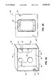
- FIG. 3a is a perspective view of a typical electrical box which may be mounted onto the mounting bracket of the present invention.
- FIG. 3b is a frontal view of a faceplate accompanying the electrical box shown in FIG. 3a.
- FIG. 4 is a top cross-sectional view of the bracket of the present invention attached to two corresponding wall studs to illustrate the manner in which an electrical box may be mounted onto the bracket of the present invention.
- FIG. 5 is a side cross-sectional view of the components shown in FIG. 4 taken along the line 5--5 in FIG. 4.
- FIG. 6 is a top view of a bracket of the present invention, wherein the bracket has three electrical boxes, each having a different depth, attached thereto.
- FIGS. 1 and 2 there are shown a frontal and a side view, respectively, of a preferred embodiment of the mounting bracket of the present invention, wherein the bracket 10 takes the form of a substantially flat and elongated frame 12.
- Frame 12 is preferably constructed of a relatively rigid and conductive material. The rigidity ofthe material provides the frame 12 with the necessary structural strength and the conductivity enables the frame 12 to function as an electrical ground.
- frame 12 may be constructed of 20 gauge galvanized sheet metal.
- Frame 12 comprises a front planar face 14, a rear planar face 16 (FIG. 2), and a first 18 and second 20 opposing ends, each end preferably having a hole 22 therein for attaching the frame 12 to a corresponding wall stud (not shown).
- Each of the ends 18, 20 preferably has an attachable flat surface 24 which is bent upward from the body of the frame 12.
- the surface24 is elevated above the front face 14 of the frame 12 and is substantiallyparallel thereto. This can be seen more clearly in FIG. 2, wherein the surface 24 is clearly shown to be elevated above the front face 14 of the frame 12.
- the distance by which the surface 24 is raised above the front face 14 is determined by the thickness of the faceplate (not shown) which is attached to the frame and the size of the head of the screw (not shown)which is used to attach the faceplate to the frame. Although this distance may vary depending upon the faceplate and the screw used, it is preferablyabout 0.5 centimeters. It is the surface 24 at each end of the frame 12 which is attached to a corresponding wall stud. Because wall studs are typically separated by a distance of either sixteen or twenty-four inches,the two elevated surfaces 24 are also preferably separated by either sixteen or twenty-four inches.
- a substantial cut-out portion 26 which serves to define a top edge 28 and a bottom edge 30 in the frame.
- the cut-out portion 26 preferably has a height of between three and three and a half inches to ensure that it is no taller than a typical electricalbox.
- the outer section 29 of the entire top edge 28 is preferably bent backward at substantially a right angle with respect to the front face 14 of the frame 12 to form a top lip 32 as shown in FIG. 2.
- the outer section 31 of the entire bottom edge 30 is also preferably bent backward at substantially a right angle with respect to the front face 14 of the frame 12 to form a bottom lip 33.
- the frame 12 further comprises a plurality of bevelled corners 34 rather than sharp corners. These bevelled corners 34 allow nails to be driven into locations where the corners otherwise would have been. This is important because frame 12 is meant to be attached to wall studs. Since a large number of structures need to be attached to the studs, it is desirable to keep as much of the stud free as possible to accommodate the other structures.
- the bevelled corners 34 achieve this purpose.
- the mounting bracket 10 of the present invention thus far described may be used to conveniently mount electrical boxes between two wall studs.
- a typical electrical box 40 which may be mounted to bracket 10, and an accompanying faceplate 60, are shown in FIGS. 3a and 3b, respectively.
- Theelectrical box 40 is preferably of standard construction comprising a plurality of sides 42 having a selected depth, a back end 46, and an open front end 48.
- the back end 46 typically has a plurality of pop-out sections 50 which may be removed to gain access into the interior of the box from the back end 46.
- the box further comprises two extensions 52 which extend from the sides 42 into the interior of the box 40, each extension 52 preferably having a threaded hole 54 therein for receiving a screw (not shown).
- the accompanying faceplate 60 is also preferably of standard construction having two holes 62 and a central cut-out portion 64.
- the holes 62 are selectively located such that they are in alignment with the threaded holes 54 in the extensions 52 of the electrical box 40.
- screws may be inserted through holes 62 and driven into the threaded holes 54 of the box 40 to fasten the faceplate 60 to the electrical box 40.
- the cut-out portion 64 allows access to the interior of the box 40 after the faceplate60 is attached to the box 40.
- FIG. 4 shows a top cross-sectional view of the bracket 10 of the present invention and two corresponding wall studs 70
- the bracket 10 is first attached to the studs 70 byplacing each of the elevated surfaces 24 against the front face 72 of a corresponding wall stud 70, and inserting a screw 74 through the hole 22 in each surface 24 and driving the screw 74 into each of the studs 70 to secure the bracket 10 to the two studs 70.
- the front face 14 of the bracket 10 is substantially flush with the plane 75 formed by the front faces 72 of the two studs 70.
- the electrical box 40 is placed against the bracket 10 with the open front end48 of the box 40 placed flush against the rear face 16 of the bracket 10.
- the faceplate 60 accompanying the box 40 is placed against the front face 14 of the bracket 10 opposite the electrical box 40.
- the faceplate 60 is aligned with the electric box 40 such that the holes 62 (FIG. 3b) in the faceplate 60 are aligned with the threaded holes 54 (FIG. 3a) in the extensions 52 from the box 40.
- FIG. 5 wherein a cross-sectional view, taken along line 5--5 in FIG. 4, is provided of the bracket 10, box 40, and faceplate 60.
- FIG. 5 when the front end 48 of the box 40 is placed against the rear face 16 of the bracket 10, a top portion 76 of thebox 40 contacts the top edge 28 of the bracket 10, and a bottom portion 78 of the box 40 contacts the bottom edge 30 of the bracket 10.
- the faceplate 60 when the faceplate 60 is placed against the front face 14 of the bracket, a top portion 80 of the faceplate 60 contacts the top edge 28 of the bracket, and a bottom portion 82 of the faceplate 60 contacts the bottom edge 30 of the bracket 10.
- the screws 84 do not go through either the top edge 28 or the bottom edge 30 of the bracket 10 but instead passes through the central cut-out portion 26 of the bracket 10. This obviates any need to drill holes into the bracket 10. Because the screws 84 pass through the central cut-out portion 26 and thus are not constrained by holes in the edges 28, 30, it is inherent that one may slide the box 40 and faceplate 60 along the length of the bracket 10 to place the box 40 and faceplate 60 at any desired position along the bracket 10. However, if desired, screws 84 may be driven through the edges 28, 30 of the bracket 10 without adversely affecting the function of the bracket 10. It should be noted at this pointthat the box 40 and faceplate 60 need not be secured to the bracket 10 by means of a screw.
- box 40 and faceplate 60 may be securedto the bracket 10 by gluing or even by welding. These and other means for securing the box 40 and the faceplate 60 to the bracket 10 are within the scope and spirit of the invention.
- a plurality of electrical boxes may be mounted onto a single bracket 10.
- a bracket 10 of the presentinvention having three electrical boxes mounted thereon is shown in FIG. 6,wherein a top view is provided of the bracket 10 and the three boxes A, B and C.
- the three boxes A, B, C all have different depths.
- box B is deeper than box A
- box C is shallower than box A.
- the front ends 90 of all three boxes A, B, C, after mounting to the bracket 10 are substantially flush with the wall 92 between the two studs 94. As discussed previously, this is the desired result. Therefore, the bracket of the present invention is capable of accommodating on the same bracket aplurality of boxes having different depths.
Abstract
Description
Claims (10)
Priority Applications (7)
| Application Number | Priority Date | Filing Date | Title |
|---|---|---|---|
| US08/000,189 US5330137A (en) | 1993-01-04 | 1993-01-04 | Apparatus and method for mounting an electrical box between studs in a wall |
| CA002133476A CA2133476C (en) | 1993-01-04 | 1994-01-04 | Apparatus and method for mounting an electrical box between studs in a wall |
| PCT/US1994/000122 WO1994016445A1 (en) | 1993-01-04 | 1994-01-04 | Apparatus and method for mounting an electrical box between studs in a wall |
| MX9400251A MX9400251A (en) | 1993-01-04 | 1994-01-04 | DEVICE AND METHOD FOR MOUNTING AN ELECTRICAL BOX BETWEEN STUDS ON A WALL. |
| EP94906031A EP0657060B1 (en) | 1993-01-04 | 1994-01-04 | Apparatus and method for mounting an electrical box between studs in a wall |
| DE69410068T DE69410068T2 (en) | 1993-01-04 | 1994-01-04 | DEVICE AND METHOD FOR WALL MOUNTING AN ELECTRICAL HOUSING BETWEEN POST |
| AT94906031T ATE165932T1 (en) | 1993-01-04 | 1994-01-04 | APPARATUS AND METHOD FOR WALL MOUNTING AN ELECTRICAL ENCLOSURE BETWEEN POSTS |
Applications Claiming Priority (1)
| Application Number | Priority Date | Filing Date | Title |
|---|---|---|---|
| US08/000,189 US5330137A (en) | 1993-01-04 | 1993-01-04 | Apparatus and method for mounting an electrical box between studs in a wall |
Publications (1)
| Publication Number | Publication Date |
|---|---|
| US5330137A true US5330137A (en) | 1994-07-19 |
Family
ID=21690320
Family Applications (1)
| Application Number | Title | Priority Date | Filing Date |
|---|---|---|---|
| US08/000,189 Expired - Lifetime US5330137A (en) | 1993-01-04 | 1993-01-04 | Apparatus and method for mounting an electrical box between studs in a wall |
Country Status (7)
| Country | Link |
|---|---|
| US (1) | US5330137A (en) |
| EP (1) | EP0657060B1 (en) |
| AT (1) | ATE165932T1 (en) |
| CA (1) | CA2133476C (en) |
| DE (1) | DE69410068T2 (en) |
| MX (1) | MX9400251A (en) |
| WO (1) | WO1994016445A1 (en) |
Cited By (40)
| Publication number | Priority date | Publication date | Assignee | Title |
|---|---|---|---|---|
| US5619263A (en) * | 1995-03-21 | 1997-04-08 | Erico International Corporation | Box hanger and method |
| US5678799A (en) * | 1995-06-07 | 1997-10-21 | Hubbell Incorporated | Adjustable hanger assembly |
| US5927667A (en) * | 1996-09-27 | 1999-07-27 | Hubbell Incorporated | Electrical box mounting bracket |
| US5931425A (en) * | 1997-07-01 | 1999-08-03 | Oliva; John H. | Apparatus and method for mounting and stabilizing electrical junction boxes between wall studs |
| US5954304A (en) * | 1996-10-25 | 1999-09-21 | Hubbell Incorporated | Adjustable hanger assembly |
| AU746784B2 (en) * | 1998-05-18 | 2002-05-02 | Esco Industries Pty Ltd | Service outlet mounting system |
| US6573449B2 (en) | 2001-04-25 | 2003-06-03 | Paul A. Vrame | Floor stand for electrical box having plaster ring |
| US6590155B2 (en) | 2001-04-25 | 2003-07-08 | Paul A. Vrame | Floor stand for mounting electrical box and for supporting conduit |
| US6595476B1 (en) | 2001-07-20 | 2003-07-22 | Donald B. Edwards | Acoustic ceiling box support |
| US6666419B1 (en) | 1999-11-23 | 2003-12-23 | 3244 Corporation | Bracket assembly for mounting electrical box between two building studs |
| US20050001123A1 (en) * | 2003-01-22 | 2005-01-06 | Cheatham James F. | Electrical box mounting brackets |
| US20050034407A1 (en) * | 2003-07-28 | 2005-02-17 | Snyder Darryl L. | Support frame for duct |
| US20050067546A1 (en) * | 2003-09-29 | 2005-03-31 | Cong Dinh | Mounting bracket for an electrical box |
| US7025314B1 (en) | 2004-05-08 | 2006-04-11 | Tammy Thomas | Multi-functional mounting bracket with integral electrical box |
| US20060180555A1 (en) * | 2005-02-05 | 2006-08-17 | Asustek Computer Inc. | Rack bracket structure |
| US7104836B1 (en) * | 2000-01-05 | 2006-09-12 | Protectconnect | Electrical wiring system |
| US20060237601A1 (en) * | 2005-03-29 | 2006-10-26 | Cooper Technologies Company | Bracket for mounting an electrical device |
| US20070084617A1 (en) * | 2003-09-29 | 2007-04-19 | Thomas & Betts International, Inc. | Adjustable mounting bracket assembly for mounting an electrical box |
| US20070181330A1 (en) * | 2003-09-29 | 2007-08-09 | Thomas & Betts International, Inc. | Far-side support for brackets |
| US20070295870A1 (en) * | 2006-06-12 | 2007-12-27 | Peterson Erik R | Wall mounted workstation |
| US20080020632A1 (en) * | 2004-03-13 | 2008-01-24 | Gorman Michael P | Universal electrical wiring component |
| US20080093552A1 (en) * | 2004-11-26 | 2008-04-24 | Protectconnect | Motion detector module |
| US20100000783A1 (en) * | 2008-07-03 | 2010-01-07 | Cooper Technologies Company | Floor stand for mounting an electrical box |
| US20100078532A1 (en) * | 2008-09-26 | 2010-04-01 | Thomas & Betts International, Inc. | Prefabricated mounting bracket assembly |
| US7718893B2 (en) | 2006-07-29 | 2010-05-18 | Protectconnect | Adjustable plaster ring cover |
| US7762838B2 (en) | 2002-05-23 | 2010-07-27 | Protectconnect | Safety module electrical distribution system |
| US20100270446A1 (en) * | 2009-04-28 | 2010-10-28 | Phillips Bruce G | Universal Adjustable Box Bracket |
| US20100282939A1 (en) * | 2008-02-05 | 2010-11-11 | Eric Rinderer | Self-Correcting Conductor Positioning Bracket |
| US8105107B2 (en) | 2000-01-05 | 2012-01-31 | Protectconnect, Inc. | Safety electrical outlet and switch system |
| US20120272615A1 (en) * | 2011-04-27 | 2012-11-01 | Jonathan Martin Evans | Electrical junction box mount |
| US8403289B1 (en) | 2008-10-15 | 2013-03-26 | Eric R. Rinderer | Universal electric box mounting device |
| WO2013156879A2 (en) | 2012-04-18 | 2013-10-24 | Spallina Giacomo | Tool for installation of building elements |
| US20150008198A1 (en) * | 2013-07-06 | 2015-01-08 | Atlas Sound Lp | Half-rack crossbar systems |
| US9564744B2 (en) | 2013-06-27 | 2017-02-07 | Thomas & Betts International Llc | Adjustable bracket assembly |
| US9583926B2 (en) | 2013-06-04 | 2017-02-28 | Thomas & Betts International Llc | Hanger bar |
| US10077866B2 (en) | 2014-06-06 | 2018-09-18 | Cooper Technologies Company | Stud-to-stud mounting bracket for electrical or communication device |
| US10084298B2 (en) | 2015-07-08 | 2018-09-25 | David Terwilleger | Self-measuring wall box bracket |
| US11473721B2 (en) | 2019-06-03 | 2022-10-18 | Erico International Corporation | Mounting bracket for electrical boxes |
| US11639756B1 (en) | 2022-07-06 | 2023-05-02 | Michael G. Jacoway | Unitary stub out and rough-in plumbing valve cylinder including a rear mounting plate with an integral conduit member extending there from with support and leveling flange members in cooperation therewith |
| US11959588B2 (en) | 2022-10-18 | 2024-04-16 | Erico International Corporation | Mounting bracket for electrical boxes |
Families Citing this family (1)
| Publication number | Priority date | Publication date | Assignee | Title |
|---|---|---|---|---|
| DE102006026264B4 (en) * | 2006-06-02 | 2009-12-10 | Benteler Automobiltechnik Gmbh | Measuring arrangement and use of the measuring arrangement |
Citations (17)
| Publication number | Priority date | Publication date | Assignee | Title |
|---|---|---|---|---|
| US1288024A (en) * | 1915-03-11 | 1918-12-17 | Julian H Kendig | Bracket for electrical apparatus. |
| US1786004A (en) * | 1929-01-30 | 1930-12-23 | Nat Electric Prod Corp | Clamp for crossbars |
| US1790031A (en) * | 1927-03-23 | 1931-01-27 | William W Vaughn | Support |
| US1933358A (en) * | 1929-04-15 | 1933-10-31 | Edward L Kappelman | Outlet box |
| US1982957A (en) * | 1930-11-01 | 1934-12-04 | All Steel Equip Company | Outlet box and hanger bar |
| US2032636A (en) * | 1933-10-23 | 1936-03-03 | George D Seckinger | Outlet box hanger |
| US2223910A (en) * | 1938-04-11 | 1940-12-03 | Michael J Gallagher | Outlet box securing means |
| US2440324A (en) * | 1948-04-27 | Mounting bracket fob instrument | ||
| US3038020A (en) * | 1959-02-03 | 1962-06-05 | Pass & Seymour Inc | Mounting strap for interchangeable wiring devices |
| US3659037A (en) * | 1971-04-30 | 1972-04-25 | Cardinal Of Adrian | Electrical outlet box |
| US3917899A (en) * | 1972-08-04 | 1975-11-04 | Michael J Oliver | Plate for adjustably mounting electrical receptacle |
| US4569458A (en) * | 1981-09-14 | 1986-02-11 | Horsley Larry L | Mounting for electrical outlet box |
| US4757967A (en) * | 1986-09-02 | 1988-07-19 | Erico International Corporation | Box support |
| US4964525A (en) * | 1989-09-21 | 1990-10-23 | G.B. Electrical Inc. | Electrical box mounting bracket |
| US4967990A (en) * | 1989-01-26 | 1990-11-06 | B-Line Systems, Inc. | Support for an electrical box |
| US5005792A (en) * | 1989-04-07 | 1991-04-09 | B-Line Systems, Inc. | Bracket for mounting an electrical switchbox on a wall stud |
| US5114105A (en) * | 1990-11-08 | 1992-05-19 | Young John A | Electrical box support bracket |
Family Cites Families (6)
| Publication number | Priority date | Publication date | Assignee | Title |
|---|---|---|---|---|
| US2701908A (en) * | 1950-11-24 | 1955-02-15 | Arthur I Appleton | Bar hanger installation jig |
| DE1689196U (en) * | 1954-03-06 | 1954-12-16 | Standard Elek Zitaets Ges Ag | FASTENING ARRANGEMENT AND COVER OF EQUIPMENT ARRANGED IN FRAMES. |
| US2917263A (en) * | 1957-02-27 | 1959-12-15 | Appleton Electric Co | Electrical fixture fastener |
| US4135337A (en) * | 1977-09-12 | 1979-01-23 | Medlin Lewis B | Mounting means for electric outlet box |
| US4533060A (en) * | 1985-01-09 | 1985-08-06 | Medlin Lewis B | Mounting bracket for electrical outlet boxes |
| US4688693A (en) * | 1986-08-04 | 1987-08-25 | Medlin Jr Lewis B | Outlet box bracket with stabilizer |
-
1993
- 1993-01-04 US US08/000,189 patent/US5330137A/en not_active Expired - Lifetime
-
1994
- 1994-01-04 CA CA002133476A patent/CA2133476C/en not_active Expired - Fee Related
- 1994-01-04 EP EP94906031A patent/EP0657060B1/en not_active Expired - Lifetime
- 1994-01-04 DE DE69410068T patent/DE69410068T2/en not_active Expired - Fee Related
- 1994-01-04 MX MX9400251A patent/MX9400251A/en not_active IP Right Cessation
- 1994-01-04 AT AT94906031T patent/ATE165932T1/en not_active IP Right Cessation
- 1994-01-04 WO PCT/US1994/000122 patent/WO1994016445A1/en active IP Right Grant
Patent Citations (17)
| Publication number | Priority date | Publication date | Assignee | Title |
|---|---|---|---|---|
| US2440324A (en) * | 1948-04-27 | Mounting bracket fob instrument | ||
| US1288024A (en) * | 1915-03-11 | 1918-12-17 | Julian H Kendig | Bracket for electrical apparatus. |
| US1790031A (en) * | 1927-03-23 | 1931-01-27 | William W Vaughn | Support |
| US1786004A (en) * | 1929-01-30 | 1930-12-23 | Nat Electric Prod Corp | Clamp for crossbars |
| US1933358A (en) * | 1929-04-15 | 1933-10-31 | Edward L Kappelman | Outlet box |
| US1982957A (en) * | 1930-11-01 | 1934-12-04 | All Steel Equip Company | Outlet box and hanger bar |
| US2032636A (en) * | 1933-10-23 | 1936-03-03 | George D Seckinger | Outlet box hanger |
| US2223910A (en) * | 1938-04-11 | 1940-12-03 | Michael J Gallagher | Outlet box securing means |
| US3038020A (en) * | 1959-02-03 | 1962-06-05 | Pass & Seymour Inc | Mounting strap for interchangeable wiring devices |
| US3659037A (en) * | 1971-04-30 | 1972-04-25 | Cardinal Of Adrian | Electrical outlet box |
| US3917899A (en) * | 1972-08-04 | 1975-11-04 | Michael J Oliver | Plate for adjustably mounting electrical receptacle |
| US4569458A (en) * | 1981-09-14 | 1986-02-11 | Horsley Larry L | Mounting for electrical outlet box |
| US4757967A (en) * | 1986-09-02 | 1988-07-19 | Erico International Corporation | Box support |
| US4967990A (en) * | 1989-01-26 | 1990-11-06 | B-Line Systems, Inc. | Support for an electrical box |
| US5005792A (en) * | 1989-04-07 | 1991-04-09 | B-Line Systems, Inc. | Bracket for mounting an electrical switchbox on a wall stud |
| US4964525A (en) * | 1989-09-21 | 1990-10-23 | G.B. Electrical Inc. | Electrical box mounting bracket |
| US5114105A (en) * | 1990-11-08 | 1992-05-19 | Young John A | Electrical box support bracket |
Cited By (62)
| Publication number | Priority date | Publication date | Assignee | Title |
|---|---|---|---|---|
| US5619263A (en) * | 1995-03-21 | 1997-04-08 | Erico International Corporation | Box hanger and method |
| US5678799A (en) * | 1995-06-07 | 1997-10-21 | Hubbell Incorporated | Adjustable hanger assembly |
| US5927667A (en) * | 1996-09-27 | 1999-07-27 | Hubbell Incorporated | Electrical box mounting bracket |
| US6209836B1 (en) | 1996-09-27 | 2001-04-03 | Hubbell Incorporated | Electrical box mounting bracket |
| US5954304A (en) * | 1996-10-25 | 1999-09-21 | Hubbell Incorporated | Adjustable hanger assembly |
| US5931425A (en) * | 1997-07-01 | 1999-08-03 | Oliva; John H. | Apparatus and method for mounting and stabilizing electrical junction boxes between wall studs |
| AU746784B2 (en) * | 1998-05-18 | 2002-05-02 | Esco Industries Pty Ltd | Service outlet mounting system |
| US6666419B1 (en) | 1999-11-23 | 2003-12-23 | 3244 Corporation | Bracket assembly for mounting electrical box between two building studs |
| US8678856B2 (en) | 2000-01-05 | 2014-03-25 | Protectconnect | Safety electrical outlet and switch system |
| US8388371B2 (en) | 2000-01-05 | 2013-03-05 | Protectconnect, Inc. | Safety electrical outlet and switch system |
| US8105107B2 (en) | 2000-01-05 | 2012-01-31 | Protectconnect, Inc. | Safety electrical outlet and switch system |
| US7104836B1 (en) * | 2000-01-05 | 2006-09-12 | Protectconnect | Electrical wiring system |
| US6573449B2 (en) | 2001-04-25 | 2003-06-03 | Paul A. Vrame | Floor stand for electrical box having plaster ring |
| US6590155B2 (en) | 2001-04-25 | 2003-07-08 | Paul A. Vrame | Floor stand for mounting electrical box and for supporting conduit |
| US6595476B1 (en) | 2001-07-20 | 2003-07-22 | Donald B. Edwards | Acoustic ceiling box support |
| US8028408B2 (en) | 2002-05-23 | 2011-10-04 | Protectconnect | Method of manufacturing a wiring module |
| US8910377B2 (en) | 2002-05-23 | 2014-12-16 | Protectconnect | Method of manufacturing a wiring module |
| US7762838B2 (en) | 2002-05-23 | 2010-07-27 | Protectconnect | Safety module electrical distribution system |
| US7036782B2 (en) * | 2003-01-22 | 2006-05-02 | Team Manufacturing, Inc. | Electrical box mounting brackets |
| US20050001123A1 (en) * | 2003-01-22 | 2005-01-06 | Cheatham James F. | Electrical box mounting brackets |
| US20050034407A1 (en) * | 2003-07-28 | 2005-02-17 | Snyder Darryl L. | Support frame for duct |
| US20050067180A1 (en) * | 2003-09-29 | 2005-03-31 | Cong Dinh | Combination mounting bracket and adapter plate for mounting electrical boxes |
| US7271336B2 (en) | 2003-09-29 | 2007-09-18 | Thomas & Betts International, Inc. | Adjustable mounting bracket assembly for mounting an electrical box |
| US7271335B2 (en) | 2003-09-29 | 2007-09-18 | Thomas & Betts International, Inc. | Combination mounting bracket and adapter plate for mounting electrical boxes |
| US20070181330A1 (en) * | 2003-09-29 | 2007-08-09 | Thomas & Betts International, Inc. | Far-side support for brackets |
| US20070084617A1 (en) * | 2003-09-29 | 2007-04-19 | Thomas & Betts International, Inc. | Adjustable mounting bracket assembly for mounting an electrical box |
| US7521631B2 (en) | 2003-09-29 | 2009-04-21 | Thomas & Betts International, Inc. | Far-side support for brackets |
| US20050067546A1 (en) * | 2003-09-29 | 2005-03-31 | Cong Dinh | Mounting bracket for an electrical box |
| USRE44546E1 (en) | 2004-03-13 | 2013-10-22 | Protectconnect, Inc. | Universal electrical wiring component |
| USRE45430E1 (en) | 2004-03-13 | 2015-03-24 | Protectconnect | Universal electrical wiring component |
| US20080020632A1 (en) * | 2004-03-13 | 2008-01-24 | Gorman Michael P | Universal electrical wiring component |
| US7025314B1 (en) | 2004-05-08 | 2006-04-11 | Tammy Thomas | Multi-functional mounting bracket with integral electrical box |
| US20080093552A1 (en) * | 2004-11-26 | 2008-04-24 | Protectconnect | Motion detector module |
| US7544941B2 (en) | 2004-11-26 | 2009-06-09 | Protectconnect, Inc. | Motion detector module |
| US20060180555A1 (en) * | 2005-02-05 | 2006-08-17 | Asustek Computer Inc. | Rack bracket structure |
| US20060237601A1 (en) * | 2005-03-29 | 2006-10-26 | Cooper Technologies Company | Bracket for mounting an electrical device |
| US7472875B2 (en) | 2005-03-29 | 2009-01-06 | Cooper Technologies Company | Bracket for mounting an electrical device |
| US7997211B2 (en) | 2006-06-12 | 2011-08-16 | Steelcase Inc. | Wall mounted workstation |
| US20070295870A1 (en) * | 2006-06-12 | 2007-12-27 | Peterson Erik R | Wall mounted workstation |
| US7718893B2 (en) | 2006-07-29 | 2010-05-18 | Protectconnect | Adjustable plaster ring cover |
| US20100282939A1 (en) * | 2008-02-05 | 2010-11-11 | Eric Rinderer | Self-Correcting Conductor Positioning Bracket |
| US8496211B2 (en) | 2008-02-05 | 2013-07-30 | Erico International Corporation | Self-correcting conductor positioning bracket |
| US20100000783A1 (en) * | 2008-07-03 | 2010-01-07 | Cooper Technologies Company | Floor stand for mounting an electrical box |
| US7956285B2 (en) | 2008-07-03 | 2011-06-07 | Cooper Technologies Company | Floor stand for mounting an electrical box |
| US20100078532A1 (en) * | 2008-09-26 | 2010-04-01 | Thomas & Betts International, Inc. | Prefabricated mounting bracket assembly |
| US8403289B1 (en) | 2008-10-15 | 2013-03-26 | Eric R. Rinderer | Universal electric box mounting device |
| US20100270446A1 (en) * | 2009-04-28 | 2010-10-28 | Phillips Bruce G | Universal Adjustable Box Bracket |
| US20120272615A1 (en) * | 2011-04-27 | 2012-11-01 | Jonathan Martin Evans | Electrical junction box mount |
| US9209612B2 (en) * | 2011-04-27 | 2015-12-08 | Jonathan Martin Evans | Electrical junction box mount |
| WO2013156879A2 (en) | 2012-04-18 | 2013-10-24 | Spallina Giacomo | Tool for installation of building elements |
| US9583926B2 (en) | 2013-06-04 | 2017-02-28 | Thomas & Betts International Llc | Hanger bar |
| US9564744B2 (en) | 2013-06-27 | 2017-02-07 | Thomas & Betts International Llc | Adjustable bracket assembly |
| US20150008198A1 (en) * | 2013-07-06 | 2015-01-08 | Atlas Sound Lp | Half-rack crossbar systems |
| US9402330B2 (en) * | 2013-07-06 | 2016-07-26 | Atlas Sound Lp | Half-rack crossbar systems |
| US10077866B2 (en) | 2014-06-06 | 2018-09-18 | Cooper Technologies Company | Stud-to-stud mounting bracket for electrical or communication device |
| US10711940B2 (en) | 2014-06-06 | 2020-07-14 | Eaton Intelligent Power Limited | Stud-to-stud mounting bracket for electrical or communication device |
| US11300246B2 (en) | 2014-06-06 | 2022-04-12 | Eaton Intelligent Power Limited | Stud-to-stud mounting bracket for electrical or communication device |
| US11698165B2 (en) | 2014-06-06 | 2023-07-11 | Eaton Intelligent Power Limited | Stud-to-stud mounting bracket for electrical or communication device |
| US10084298B2 (en) | 2015-07-08 | 2018-09-25 | David Terwilleger | Self-measuring wall box bracket |
| US11473721B2 (en) | 2019-06-03 | 2022-10-18 | Erico International Corporation | Mounting bracket for electrical boxes |
| US11639756B1 (en) | 2022-07-06 | 2023-05-02 | Michael G. Jacoway | Unitary stub out and rough-in plumbing valve cylinder including a rear mounting plate with an integral conduit member extending there from with support and leveling flange members in cooperation therewith |
| US11959588B2 (en) | 2022-10-18 | 2024-04-16 | Erico International Corporation | Mounting bracket for electrical boxes |
Also Published As
| Publication number | Publication date |
|---|---|
| WO1994016445A1 (en) | 1994-07-21 |
| EP0657060B1 (en) | 1998-05-06 |
| DE69410068D1 (en) | 1998-06-10 |
| EP0657060A1 (en) | 1995-06-14 |
| ATE165932T1 (en) | 1998-05-15 |
| CA2133476C (en) | 2005-03-29 |
| CA2133476A1 (en) | 1994-07-21 |
| MX9400251A (en) | 1994-07-29 |
| DE69410068T2 (en) | 2000-10-26 |
| EP0657060A4 (en) | 1995-07-05 |
Similar Documents
| Publication | Publication Date | Title |
|---|---|---|
| US5330137A (en) | Apparatus and method for mounting an electrical box between studs in a wall | |
| US5931425A (en) | Apparatus and method for mounting and stabilizing electrical junction boxes between wall studs | |
| US5927667A (en) | Electrical box mounting bracket | |
| US6164610A (en) | Concealed cantilever shelf support | |
| US5386959A (en) | Box support | |
| US4448007A (en) | Wall panel fastener | |
| US4139999A (en) | Protective door shield and locking mounting | |
| US3863037A (en) | Electrical box hanger structure | |
| US6637172B2 (en) | Clip for attachment to flanges of structural steel | |
| CA2050958A1 (en) | Electrical box support bracket | |
| US4863399A (en) | Low voltage bracket | |
| WO2001026078A3 (en) | Multi-sided display holder | |
| US6206195B1 (en) | Impact protecting modular block for shielding an industrial computer from impact | |
| US3448952A (en) | Electrical box mounting clip | |
| US4544301A (en) | Keyboard assembly | |
| US7380385B2 (en) | Adjustable length decoration panel | |
| JPH0132777Y2 (en) | ||
| GB2236243A (en) | Shelf support means | |
| KR950007217A (en) | Prefabricated box body | |
| CA2211583C (en) | Stud bracket | |
| JPS5822675Y2 (en) | Knife plate support device | |
| JPH0715173Y2 (en) | Exterior case structure | |
| EP1251611B1 (en) | A structure for electrical distribution boards and the like | |
| JP3030315B2 (en) | Panel mounting device | |
| KR900000703Y1 (en) | Front plate of top pannel of refrigerator |
Legal Events
| Date | Code | Title | Description |
|---|---|---|---|
| STCF | Information on status: patent grant |
Free format text: PATENTED CASE |
|
| FEPP | Fee payment procedure |
Free format text: PAT HLDR NO LONGER CLAIMS SMALL ENT STAT AS INDIV INVENTOR (ORIGINAL EVENT CODE: LSM1); ENTITY STATUS OF PATENT OWNER: SMALL ENTITY |
|
| FPAY | Fee payment |
Year of fee payment: 4 |
|
| FEPP | Fee payment procedure |
Free format text: PAT HOLDER CLAIMS SMALL ENTITY STATUS, ENTITY STATUS SET TO SMALL (ORIGINAL EVENT CODE: LTOS); ENTITY STATUS OF PATENT OWNER: SMALL ENTITY |
|
| REMI | Maintenance fee reminder mailed | ||
| FPAY | Fee payment |
Year of fee payment: 8 |
|
| SULP | Surcharge for late payment |
Year of fee payment: 7 |
|
| FEPP | Fee payment procedure |
Free format text: ENTITY STATUS SET TO SMALL (ORIGINAL EVENT CODE: SMAL); ENTITY STATUS OF PATENT OWNER: SMALL ENTITY |
|
| FEPP | Fee payment procedure |
Free format text: PAYOR NUMBER ASSIGNED (ORIGINAL EVENT CODE: ASPN); ENTITY STATUS OF PATENT OWNER: SMALL ENTITY |
|
| FPAY | Fee payment |
Year of fee payment: 12 |