US5329694A - Apparatus for attaching a fastener to an enclosed structure - Google Patents
Apparatus for attaching a fastener to an enclosed structure Download PDFInfo
- Publication number
- US5329694A US5329694A US08/044,360 US4436093A US5329694A US 5329694 A US5329694 A US 5329694A US 4436093 A US4436093 A US 4436093A US 5329694 A US5329694 A US 5329694A
- Authority
- US
- United States
- Prior art keywords
- fastener
- tube
- attaching
- self
- cam
- Prior art date
- Legal status (The legal status is an assumption and is not a legal conclusion. Google has not performed a legal analysis and makes no representation as to the accuracy of the status listed.)
- Expired - Lifetime
Links
- 229910052751 metal Inorganic materials 0.000 claims abstract description 18
- 239000002184 metal Substances 0.000 claims abstract description 18
- 238000009434 installation Methods 0.000 claims description 36
- 238000000034 method Methods 0.000 abstract description 40
- 230000013011 mating Effects 0.000 abstract description 8
- 229910000746 Structural steel Inorganic materials 0.000 description 7
- 230000000717 retained effect Effects 0.000 description 6
- 238000004519 manufacturing process Methods 0.000 description 3
- 229910000831 Steel Inorganic materials 0.000 description 2
- 239000000446 fuel Substances 0.000 description 2
- 239000000463 material Substances 0.000 description 2
- 239000010959 steel Substances 0.000 description 2
- 229910001209 Low-carbon steel Inorganic materials 0.000 description 1
- 229910052782 aluminium Inorganic materials 0.000 description 1
- XAGFODPZIPBFFR-UHFFFAOYSA-N aluminium Chemical compound [Al] XAGFODPZIPBFFR-UHFFFAOYSA-N 0.000 description 1
- 230000009286 beneficial effect Effects 0.000 description 1
- 230000001419 dependent effect Effects 0.000 description 1
- 230000000994 depressogenic effect Effects 0.000 description 1
- 230000007246 mechanism Effects 0.000 description 1
- 238000012986 modification Methods 0.000 description 1
- 230000004048 modification Effects 0.000 description 1
- 238000003466 welding Methods 0.000 description 1
Images


Classifications
-
- B—PERFORMING OPERATIONS; TRANSPORTING
- B23—MACHINE TOOLS; METAL-WORKING NOT OTHERWISE PROVIDED FOR
- B23P—METAL-WORKING NOT OTHERWISE PROVIDED FOR; COMBINED OPERATIONS; UNIVERSAL MACHINE TOOLS
- B23P19/00—Machines for simply fitting together or separating metal parts or objects, or metal and non-metal parts, whether or not involving some deformation; Tools or devices therefor so far as not provided for in other classes
- B23P19/04—Machines for simply fitting together or separating metal parts or objects, or metal and non-metal parts, whether or not involving some deformation; Tools or devices therefor so far as not provided for in other classes for assembling or disassembling parts
- B23P19/06—Screw or nut setting or loosening machines
- B23P19/062—Pierce nut setting machines
-
- Y—GENERAL TAGGING OF NEW TECHNOLOGICAL DEVELOPMENTS; GENERAL TAGGING OF CROSS-SECTIONAL TECHNOLOGIES SPANNING OVER SEVERAL SECTIONS OF THE IPC; TECHNICAL SUBJECTS COVERED BY FORMER USPC CROSS-REFERENCE ART COLLECTIONS [XRACs] AND DIGESTS
- Y10—TECHNICAL SUBJECTS COVERED BY FORMER USPC
- Y10T—TECHNICAL SUBJECTS COVERED BY FORMER US CLASSIFICATION
- Y10T29/00—Metal working
- Y10T29/53—Means to assemble or disassemble
- Y10T29/5343—Means to drive self-piercing work part
-
- Y—GENERAL TAGGING OF NEW TECHNOLOGICAL DEVELOPMENTS; GENERAL TAGGING OF CROSS-SECTIONAL TECHNOLOGIES SPANNING OVER SEVERAL SECTIONS OF THE IPC; TECHNICAL SUBJECTS COVERED BY FORMER USPC CROSS-REFERENCE ART COLLECTIONS [XRACs] AND DIGESTS
- Y10—TECHNICAL SUBJECTS COVERED BY FORMER USPC
- Y10T—TECHNICAL SUBJECTS COVERED BY FORMER US CLASSIFICATION
- Y10T29/00—Metal working
- Y10T29/53—Means to assemble or disassemble
- Y10T29/53709—Overedge assembling means
- Y10T29/53717—Annular work
- Y10T29/53722—Annular work with radially acting tool inside annular work
-
- Y—GENERAL TAGGING OF NEW TECHNOLOGICAL DEVELOPMENTS; GENERAL TAGGING OF CROSS-SECTIONAL TECHNOLOGIES SPANNING OVER SEVERAL SECTIONS OF THE IPC; TECHNICAL SUBJECTS COVERED BY FORMER USPC CROSS-REFERENCE ART COLLECTIONS [XRACs] AND DIGESTS
- Y10—TECHNICAL SUBJECTS COVERED BY FORMER USPC
- Y10T—TECHNICAL SUBJECTS COVERED BY FORMER US CLASSIFICATION
- Y10T29/00—Metal working
- Y10T29/53—Means to assemble or disassemble
- Y10T29/53709—Overedge assembling means
- Y10T29/53717—Annular work
- Y10T29/53726—Annular work with second workpiece inside annular work one workpiece moved to shape the other
Definitions
- the body portion of the self-attaching fastener is supported in the reciprocating plunger of the installation head and the fastening portion extends axially from the plunger.
- the plunger of the installation head drives the fastener into the panel.
- the fastener is a self-piercing fastener having a pilot or barrel portion
- the fastener pierces a slug from the panel and the pilot or barrel portion is then received through the pierced panel opening.
- Such fasteners may also be installed in panels having a preformed panel opening.
- the die button then deforms the panel adjacent the panel opening into locking engagement with the fastener. Examples of pierce nuts and installation tooling are disclosed in U.S. Pat. Nos. 3,152,628, 3,648,747, 3,711,931, 4,242,793 and 4,971,499, all assigned to the assignee of the present application.
- structural metal tubes are now used in many applications, including automotive applications, requiring attachment of components and other structural members to the structural metal tubes.
- the thickness of the wall of the metal tube may be 1/8 inch or greater.
- the structural tube is preferably flattened at the point of connection.
- attachment of a component to a structural metal tube may require flattening of the tube at the point of connection, then welding a weld nut to the flattened area, or use of a clamp.
- the method and apparatus of the present invention is particularly suitable for attaching self-attaching nuts of the type described above to structural metal tubes or the metal wall of an enclosed structure, from inside the tube or structure.
- the self-attaching fastener may be installed with one stroke of the press and the area surrounding the fastener is simultaneously flattened to form a cradle or saddle for attachment of a second structural element or component.
- the method of this invention includes rigidly supporting the self-attaching fastener inside the enclosed structure on an anvil with the body portion rigidly supported on the anvil and the fastening portion extending toward and located adjacent an inner surface of the wall.
- a die member is then driven against an outer surface of the wall to attach the panel to the fastening portion of the fastener.
- the die member preferably includes an opening configured to receive the projecting fastening portion of the self-attaching fastener as the fastener is received through an opening in the metal wall and a die surface on opposite sides of the die opening.
- the fastening portion of the fastener cooperates with the die opening to pierce a slug from the wall and the wall is then driven toward the body portion of the fastener to drive the fastening portion through the wall opening.
- the wall may include a preformed opening configured to receive the fastening portion of the fastener. The method then includes continuing to drive the die member against the wall outer surface. The die portions on opposite sides of the die opening then permanently deform the wall into locking engagement with the fastening portion of the fastener, forming a secure mechanical interlock between the wall and the self-attaching fastener.
- the preferred method of this invention then includes inserting the body portion of the self-attaching fastener on a support surface of the anvil.
- the anvil with the self-attaching fastener is then inserted into the enclosed structure with the fastening portion located opposite the inner wall surface.
- the method then includes moving the fastener rigidly supported on the anvil toward the wall to locate the fastening portion adjacent the wall inner surface.
- the die member is then driven against the outer wall surface to secure the self-attaching fastener to the wall, as described.
- the anvil assembly is contracted to remove the anvil assembly from the enclosed structure.
- the method and apparatus of this invention is particularly, although not exclusively adapted to installing self-attaching fasteners in a tube, such as a structural steel tube, from inside the tube.
- the preferred embodiment of the tube and fastener assembly include a depressed flatten portion surrounding the fastener.
- the anvil assembly includes a saddle-shaped depression in the cylindrical surface surrounding the fastener pocket and the die member includes a mating saddle-shaped embossment surrounding the die opening. The die member then deforms the tube wall into the saddle-shaped depression in the anvil during installation of the self-attaching fastener.
- the fastening portion of the fastener is then installed generally flush with the lower surface of the saddle-shaped depression or emboss formed in the tube wall.
- the disclosed embodiment of the anvil assembly includes two relatively movable parts having mating inclined surfaces.
- a threaded member is provided which threadably biases one of the anvil parts to expand or contract the anvil assembly, as described.
- the anvil parts having the mating inclined surfaces may be relatively moved by any suitable means, such as a hydraulic or pneumatic piston or cam assembly.
- one of the parts is wedge-shaped having an inclined surface and generally rectangular in cross-section.
- the other of the parts includes a generally rectangular slot having an inclined bottom wall which slidably receives the wedge-shaped part.
- the mandrel preferably includes a cylindrical outer surface.
- the threaded member is then threaded through an opening in the mandrel and connected to the wedge-shaped part.
- the wedge-shaped part is then moved relative to the other part by threading the threaded adjustment member.
- the anvil assembly for installing self-attaching fasteners in a tube further includes a tube cradle which rigidly supports the tube and anvil assembly during installation of the self-attaching fastener.
- the method and apparatus of this invention may thus be utilized to install conventional self-attaching fasteners to a metal wall of an enclosed structure from inside the structure with one stroke of a die press.
- the method and apparatus of this invention may be utilized to install self-attaching fasteners, such as pierce and clinch nuts and studs, in a structural steel tube, from inside the tube, and the tube may be simultaneously embossed to provide a flush-mounting.
- the method and apparatus of this invention may be utilized for mass production applications, wherein several self-attaching fasteners are installed with each stroke of the press.
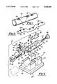
- FIG. 1 is a side perspective view of a tube having a plurality of self-attaching fasteners installed from inside the tube by the method and apparatus of this invention
- FIG. 2 is a side perspective view of a contoured structural tube, such as used by the automotive industry, with a plurality of self-attaching fasteners installed in the tube from inside the tube by the method of this invention;
- FIG. 3 is an exploded view of one preferred embodiment of an anvil assembly for installing self-attaching fasteners in a tube by the method of this invention
- FIG. 4 is a side cross-sectional view of the anvil assembly shown in FIG. 3 with a tube shown in phantom, prior to installation of the self-attaching fastener;
- FIG. 5 is a cross-sectional view of the anvil assembly shown in FIG. 4, following installation of a self-attaching fastener in a tube;
- FIG. 6 is a cross-sectional view of the anvil assembly, tube and nut assembly shown in FIG. 5, in the direction of view arrows 6--6, prior to installation of the self-attaching fastener in the tube;
- FIG. 7 is a partial cross-sectional view of a tube and nut assembly with a die member, illustrating the die member
- FIG. 8 is an end view of one embodiment of a die member for installing universal pierce nuts in the direction of view arrows 8--8 in FIG. 6;
- FIG. 9 is a side cross-sectional view of the die member shown in FIGS. 6 to 8.
- FIG. 10 is a partial side cross-sectional view of the die member shown in FIG. 9, in the direction of view arrows 10--10.
- FIGS. 1 and 2 illustrate a preferred embodiment of pierce nuts 22 installed in cylindrical tubes or pipes 20 and 24, respectively. It will be understood, however, that the method and apparatus of this invention may be adapted to install other types of self-attaching fasteners to a wall of other enclosed structures including, for example, enclosed channels, metal housings, rectangular pipes, and the like. Further, the method of this invention is particularly, but not exclusively adapted to install self-attaching fasteners to a metal wall of an enclosed structure requiring substantial force to install the self-attaching fastener.
- FIG. 1 illustrates a tube 20 having a plurality of pierce nuts 22 installed by the method of this invention from inside the tube. The tube may be formed of steel, aluminum or other materials.
- FIG. 1 illustrates a tube 20 having a plurality of pierce nuts 22 installed by the method of this invention from inside the tube.
- the tube may be formed of steel, aluminum or other materials.
- FIG. 2 illustrates a tubular automotive structural cross member 24 which may be formed of structural steel for example.
- a typical automotive cross member is formed of 1010 steel having a wall thickness of about 1/8 inch and an outside diameter of 23/8 inches.
- the cylindrical tubes 20 and 24 include saddle-shaped depressions 26 having flat bottom surfaces surrounding the pierce nuts 22. These flats may be utilized to receive and support other structural members (not shown), such as exhaust mounting brackets, fuel lines and the like.
- FIGS. 1 and 2 which is a preferred embodiment of the invention. It is understood, however, that the invention is not limited to the installation of pierce nuts or the installation of self-attaching fasteners in a cylindrical tube.
- FIG. 3 is an exploded view of the anvil assembly 28 illustrated in FIGS. 4 to 6 which may be utilized for the method of this invention.
- the anvil assembly 28 includes cam parts 30 and 32, comprising nut holder 30 and cam 32.
- the nut holder 30 includes a nut pocket 34 which is configured to receive the body portion 33 of pierce nut 22 (see FIG. 6).
- the cylindrical surface 35 of the nut holder 30 further includes a saddle-shaped recess 36 which surrounds the nut pocket 34 and forms the saddle-shaped recess 26 in the tube, as shown in FIGS. 1 and 2, as described hereinbelow.
- the nut holder includes an axial slot 38 having an inclined cam surface 40 which receives the cam 32, as described below.
- the planar side surfaces 41 of the nut holder include vertical slots 42 which receive the guide keys 44.
- the planar side walls 41 further include transverse bores 46 which receive dowel pins 48.
- the cam 32 is rectangular in cross-section and includes an inclined surface 50, which is received within slot 38 and biased against mating inclined surface 40 of nut holder 30.
- Inclined grooves 52 are provided in the side surfaces of cam 32 which receive dowel pins 48 which guide the movement of the nut holder 30 along the mating inclined surfaces 40 and 50.
- the rearward end of the cam 32 includes a C-shaped slot 54 which receives the head 56 of adjustment screw 58 for relative movement of the cam 32, as described below.
- the cam parts 30 and 32 are received in a slot or channel 62 in mandrel 60.
- the bottom wall of the channel 62 includes a rail 64 which receives the bottom of the cam 32.
- a stop 66 is provided on the mandrel to accurately locate the tube T during installation of the self-attaching fastener, as described below.
- the keys 44 are received in slots 68 of the mandrel and retained therein by socket head cap screws 70.
- Flats 72 are provided in the side wall of the mandrel, which are machined to accurately fit within the rectangular groove 74 of the guide block 76.
- the outer surface 77 of the mandrel 60 which is received within the enclosed structure, is preferably configured to conform to the opposed surfaces off the enclosed structure. In this case, the outer surface 77 is cylindrical to conform to the cylindrical inner surface of the tube T.
- the rearward end of the slot 62 is covered with a cover plate 78 having a tongue portion 80 which is received within the tube T to which the self-attaching fastener is installed.
- the tongue 80 may include a cylindrical top surface to conform to the cylindrical inner surface of the tube.
- the cover plate 78 is retained to the mandrel 60 by cap screws 82.
- the threaded portion 83 of the adjustment screw 58 is threadably received in a threaded bore 84 in the rearward end of the mandrel 60 as shown in FIGS. 4 and 5.
- the head portion 56 of the adjustment member is received in C-shaped slot 54 in the wedge 32 and hand nut or knob 86 is provided at the rearward end of the adjustment screw 58.
- the cam 32 may thus be extended or retracted within the channel 62 of mandrel 60 to raise or lower the nut holder 30 by rotating the knob 86 of adjustment screw 58.
- the free end 88 of cam 32 is received through an opening 92 of end stop 90.
- the end stop 90 prevents longitudinal movement of the nut holder 30 during installation of the nut as shown in FIGS. 4 and 5 and described hereinbelow.
- the cylindrical portion 77 of the mandrel 60 is received in cylindrical channel 98 of tube cradle 96 following receipt of the tube T on the mandrel. If, however, the tube is rectangular, for example, the tube cradle 98 will include a rectangular channel and the surface 77 will be rectangular to conform to the surface of the tube.
- the guide block 76 and tube cradle 96 may be welded or otherwise secured to base plate 100.
- FIGS. 4 to 6 The operation of the anvil assembly is best shown in FIGS. 4 to 6.
- the body portion 33 of the pierce nut 22 is inserted into the nut pocket 34 with the cam 32 retracted in the mandrel 60 as shown in FIG. 4.
- the anvil assembly 28 With the cam 32 retracted as shown in FIG. 4, the anvil assembly 28 has a minimum width or diameter, such that the pierce nut 22 easily clears the inside surface of the tube T as shown in FIG. 4.
- the anvil assembly 28 is then inserted into the tube T until the tube engages the stop 66 as shown at T 2 in FIG. 4.
- the tube and anvil assembly is then received in the tube cradle and guide block 76, respectively, of base assembly 94.
- the cam 32 is then extended by turning adjustment screw 58 as shown in FIGS. 5 and 6.
- the cam 32 is extended to the left in FIG. 5, the nut holder 30 is moved upwardly in FIGS. 5 and 6 as the inclined cam surface 40 rides upwardly on the inclined cam surface 50 of the cam 32.
- the pierce nut 22 is thus raised in the nut pocket 34 of the nut holder 30 until the pilot portion 31 is located adjacent an inner surface of the tube T as shown in FIG. 6.
- the pierce nut 22 is thus ready for installation.
- the pierce nut 22 is rigidly and immovably supported in the anvil assembly as shown in FIG. 6. That is, the elements supporting the pierce nut 22 are stacked in face-to-face relation as shown in FIG. 6 to rigidly support the nut, including the nut holder 30, the wedge 32, the mandrel 60, the tube T and the tube cradle 96.
- the nut pocket 34 prevents any movement of the pierce nut in the nut holder 30 and the end stop 90 prevents any movement of the nut holder.
- the self-attaching fastener 22 is then installed in the tube by the die button 120 as shown in FIG. 6.
- the die button 120 is adapted to install a pierce nut of the type shown in FIG. 6.
- the die button includes a die opening 122 which is configured to receive the projecting portion of the self-attaching fastener.
- the pilot 31 of the pierce nut (see FIGS. 6 and 7) is rectangular and therefore the die opening 122 is rectangular to closely receive the projecting pilot portion 31 of the nut.
- Die surfaces 124 and 126 are located on opposite sides of the die opening 122.
- the die surfaces 124 are generally triangular in cross-section having a truncated end, as best shown in FIGS. 8 and 9.
- the die surfaces 124 are generally referred to as clinching lips because they clinch metal into the nut grooves as described below.
- the end 128 of the die button is generally flat having chamfered side surfaces 130 to generally conform to the saddle-shaped recess 36 in the nut holder. It will be understood that the configuration of the die button 120 will depend upon the configuration of the self-attaching fastener. Other types of die members are disclosed in the above-referenced U.S. patents.
- the die button 120 is located opposite the self-attaching fastener 22, which is rigidly supported on the anvil assembly 28 as shown in FIG. 6.
- the projecting portion 31 of the self-attaching fastener is preferably located adjacent the inner surface of the tube T.
- the die opening 122 is coaxially aligned with and configured to receive the projecting pilot portion 31 of the nut.
- the die button 120 is then driven into contact with the outer surface of the tube T to install the self-attaching fastener in the tube.
- the die member 120 may be supported in a retainer 132, as shown in phantom in FIG. 6.
- the die button may be retained in the die holder 132 by a set screw 134 or other suitable means.
- the die holder 132 is then secured in a die platen of a die press (not shown) and the base assembly 94 is retained in the opposite die platen.
- the base assembly 94 is retained in the lower die platen and the die button 120 and holder 132 are retained in the upper die platen.
- this arrangement can be reversed.
- the die button 120 is thus driven against the outer surface of the tube T as the press reciprocates.
- FIGS. 5, 6 and 7 best illustrate the installation of the pierce nut 22 in the wall of the tube T.
- the pierce nut 22 having a projecting pilot 31 is installed in a cylindrical tube T
- the pierce nut is preferably oriented as shown, such that the pierce nut grooves 140 face generally perpendicular to the axis of the tube as best shown in FIGS. 6 and 7. That is, the pierce nut is oriented generally transverse to the longitudinal axis of the tube.
- the pilot portion 31 is received in the die opening 122 to pierce a slug 142 from the tube wall as shown in FIG. 7.
- the clinching lips 124 then deform the wall of the tube into locking engagement with the pierce nut grooves 140 and the die member drives the tube wall into mating engagement with the flange or shoulder portions 144 of the body portion of the nut.
- the end of the die button including the flat end face 128 and the chamfered side surfaces 130 generally conform to the saddle-shaped recess 36 in the nut holder 30, such that a saddle-shaped recess 146 is formed in the tube wall simultaneously with the installation of the pierce nut 22 in the tube.
- This saddle-shaped recess 146 is particularly beneficial in structural tubing because structural elements or components may then be rigidly attached to the structural tube using the integrally-formed self-attaching fastener 22.
- the pierce nut 22 may include a threaded bore 138 which threadably receives a bolt or screw (not shown) for attachment of other elements.
- a bracket for a fuel line or another structural element may thus be rigidly attached to the tube.
- a multiple part mandrel assembly having a plurality of nut holders 30 may be supported on a single cam or a plurality of cams.
- the tube preferably has a configured shape, such as the structural tube 24 shown in FIG. 2, the pierce nuts are preferably installed in the tube while the tube 24 is straight. The tube may then be formed into any desired shape by conventional tube forming process and tooling to form the structural tube 24 shown in FIG. 2.
- the method of this invention thus briefly includes rigidly supporting a self-attaching fastener 22 in an anvil assembly 28 and locating the projecting fastening portion 31 of the fastener adjacent the inner surface of the enclosed structure T as shown in FIG. 6.
- the body portion 33 is supported in a pocket 34 of the anvil assembly 28, the anvil assembly is then inserted into the enclosed structure and the fastener 22 is then moved to adjacent an inner surface of the wall T while the fastener is rigidly supported on the anvil assembly.
- a die member 120 is then driven against an outer surface of the tube T to first drive the projecting portion 31 of the fastener through an opening in the panel into the die opening 122.
- the fastener is a self-piercing fastener, such as the pierce nut 22
- the projecting pilot portion 31 pierces a slug 142 from the tube wall.
- the slug 142 and the pilot portion 31 are then received in the die opening 122 as shown in FIG. 7.
- a saddle-shaped depression or emboss 146 is formed in the tube wall simultaneously with the installation of the self-attaching fastener 22 in the tube.
- the anvil assembly includes cam parts 30 and 32 having mating inclined surfaces 40 and 50, respectively, and the self-attaching fastener is moved to adjacent the inner surface of the tube T by moving one of the cam parts. Because the force of installation may be several tons where, for example, the tube or enclosed structure is formed of structural steel, the inclined surfaces should be about seven degrees to avoid lateral translation of the force of installation. Following installation, the cam 32 is again retracted by turning screw adjustment member 58 to generally the position shown in FIG. 4. The anvil assembly 28 may then be easily removed from the tube and the installation is complete.
- a retractable anvil assembly may not be required. That is, the shape of the mandrel and nut holder will be dependent upon the shape of the wall to which the self-attaching fastener is attached.
- the method and apparatus of this invention may be utilized to attach a self-clinching fastener to a tube or other enclosed structure having a preformed opening. The method of installation may be identical to the method described herein, except that the projecting portion of the fastener does not pierce the wall opening.
- the method and apparatus of this invention may be utilized in a punch, rather than a press, in which case the die member is attached to the reciprocating punch.
- the wedge 32 may be moved relative to the nut holder 30 by any suitable means, including pneumatic and hydraulic cylinders, cam or lever mechanisms and the like.
Landscapes
- Engineering & Computer Science (AREA)
- Mechanical Engineering (AREA)
- Automatic Assembly (AREA)
Abstract
Description
Claims (10)
Priority Applications (3)
| Application Number | Priority Date | Filing Date | Title |
|---|---|---|---|
| US08/044,360 US5329694A (en) | 1993-04-07 | 1993-04-07 | Apparatus for attaching a fastener to an enclosed structure |
| CA002119529A CA2119529A1 (en) | 1993-04-07 | 1994-03-21 | Method and apparatus for attaching a fastener to an enclosed structure |
| JP08724194A JP3471891B2 (en) | 1993-04-07 | 1994-04-04 | Fastener mounting device to pipe |
Applications Claiming Priority (1)
| Application Number | Priority Date | Filing Date | Title |
|---|---|---|---|
| US08/044,360 US5329694A (en) | 1993-04-07 | 1993-04-07 | Apparatus for attaching a fastener to an enclosed structure |
Publications (1)
| Publication Number | Publication Date |
|---|---|
| US5329694A true US5329694A (en) | 1994-07-19 |
Family
ID=21931956
Family Applications (1)
| Application Number | Title | Priority Date | Filing Date |
|---|---|---|---|
| US08/044,360 Expired - Lifetime US5329694A (en) | 1993-04-07 | 1993-04-07 | Apparatus for attaching a fastener to an enclosed structure |
Country Status (3)
| Country | Link |
|---|---|
| US (1) | US5329694A (en) |
| JP (1) | JP3471891B2 (en) |
| CA (1) | CA2119529A1 (en) |
Cited By (17)
| Publication number | Priority date | Publication date | Assignee | Title |
|---|---|---|---|---|
| US5487215A (en) * | 1994-02-18 | 1996-01-30 | Multifastener Corporation | Self-adjusting head |
| US6276050B1 (en) | 1998-07-20 | 2001-08-21 | Emhart Inc. | Riveting system and process for forming a riveted joint |
| US6691546B1 (en) * | 2002-10-08 | 2004-02-17 | Edward Kovalik | Rivet nut setting tool |
| US20050019137A1 (en) * | 2001-12-27 | 2005-01-27 | Shuichiro Iwatsuki | Self-piercing rivet fastening device and die used by the fastening device |
| US20050229375A1 (en) * | 2001-12-25 | 2005-10-20 | Nobuharu Naitoh | Self-piercing rivet setting apparatus and system |
| EP1714731A1 (en) * | 2005-04-18 | 2006-10-25 | Yugenkaisha Shinjo Seisakusho | Press for attaching nuts to pipes |
| EP1905534A1 (en) * | 2006-09-28 | 2008-04-02 | Shinjo Manufacturing Co. Ltd. | Press for attaching nuts to pipes |
| US20080164739A1 (en) * | 2007-01-05 | 2008-07-10 | Ford Global Technologies, Llc | Automotive vehicle seat system |
| US20080164732A1 (en) * | 2007-01-05 | 2008-07-10 | Ford Global Technologies, Llc | Automotive vehicle seat system |
| US20080164685A1 (en) * | 2007-01-05 | 2008-07-10 | Ford Global Technologies, Llc | Automotive vehicle seat system |
| US20100282920A1 (en) * | 2008-05-22 | 2010-11-11 | Mcpheeters Greg | Universal end clamp |
| EP2439016A1 (en) * | 2010-10-05 | 2012-04-11 | Arnold & Shinjo GmbH & Co. KG | Method and device for attaching piercing elements to tubes |
| US9015920B2 (en) | 1997-07-21 | 2015-04-28 | Newfrey Llc | Riveting system and process for forming a riveted joint |
| US9027220B2 (en) | 2012-08-07 | 2015-05-12 | Newfrey Llc | Rivet setting machine |
| WO2022065094A1 (en) * | 2020-09-23 | 2022-03-31 | Aoyama Seisakusho Co., Ltd. | Device and method for fixing nut to inner surface of pipe member |
| EP4163052A1 (en) * | 2021-10-08 | 2023-04-12 | Profil Verbindungstechnik GmbH & Co. KG | Device for fixing a functional element to a section of a workpiece |
| US20250297701A1 (en) * | 2022-05-19 | 2025-09-25 | T-Drill Oy | Method and device for making a t-branch for pipes |
Citations (9)
| Publication number | Priority date | Publication date | Assignee | Title |
|---|---|---|---|---|
| US139374A (en) * | 1873-05-27 | Improvement in tube-expanders | ||
| US350701A (en) * | 1886-10-12 | Tube-expander | ||
| US866644A (en) * | 1907-05-18 | 1907-09-24 | Thomas P Green | Tube-expander. |
| US1777772A (en) * | 1929-04-11 | 1930-10-07 | Maerican Flange & Mfg Co | Die mechanism |
| US1992855A (en) * | 1933-02-01 | 1935-02-26 | Bell Leon Moore | Method of securing bungs in metallic containers |
| US3526955A (en) * | 1968-03-26 | 1970-09-08 | Us Industries Inc | Method of attaching fastener components |
| US3851373A (en) * | 1973-09-06 | 1974-12-03 | K Shinjo | Method and apparatus for attachment of a nut in the inside wall of a pipe |
| US3947950A (en) * | 1974-06-24 | 1976-04-06 | Pressure Vessels, Inc. | Apparatus and method for beading tubes |
| US4985978A (en) * | 1988-03-01 | 1991-01-22 | Textron Inc. | Method for assembling a self-clinching fastening structure |
-
1993
- 1993-04-07 US US08/044,360 patent/US5329694A/en not_active Expired - Lifetime
-
1994
- 1994-03-21 CA CA002119529A patent/CA2119529A1/en not_active Abandoned
- 1994-04-04 JP JP08724194A patent/JP3471891B2/en not_active Expired - Fee Related
Patent Citations (9)
| Publication number | Priority date | Publication date | Assignee | Title |
|---|---|---|---|---|
| US139374A (en) * | 1873-05-27 | Improvement in tube-expanders | ||
| US350701A (en) * | 1886-10-12 | Tube-expander | ||
| US866644A (en) * | 1907-05-18 | 1907-09-24 | Thomas P Green | Tube-expander. |
| US1777772A (en) * | 1929-04-11 | 1930-10-07 | Maerican Flange & Mfg Co | Die mechanism |
| US1992855A (en) * | 1933-02-01 | 1935-02-26 | Bell Leon Moore | Method of securing bungs in metallic containers |
| US3526955A (en) * | 1968-03-26 | 1970-09-08 | Us Industries Inc | Method of attaching fastener components |
| US3851373A (en) * | 1973-09-06 | 1974-12-03 | K Shinjo | Method and apparatus for attachment of a nut in the inside wall of a pipe |
| US3947950A (en) * | 1974-06-24 | 1976-04-06 | Pressure Vessels, Inc. | Apparatus and method for beading tubes |
| US4985978A (en) * | 1988-03-01 | 1991-01-22 | Textron Inc. | Method for assembling a self-clinching fastening structure |
Cited By (50)
| Publication number | Priority date | Publication date | Assignee | Title |
|---|---|---|---|---|
| US5487215A (en) * | 1994-02-18 | 1996-01-30 | Multifastener Corporation | Self-adjusting head |
| US5502884A (en) * | 1994-02-18 | 1996-04-02 | Multifastener Corporation | Method of installing fasteners into a panel using a self-adjusting fastener installation head |
| US5533250A (en) * | 1994-02-18 | 1996-07-09 | Multifastener Corporation | Self-adjusting head for impacting fasteners into a panel |
| EP0813456A4 (en) * | 1994-02-18 | 1999-01-27 | Multifastener Corp | Self-adjusting head |
| US7024270B2 (en) | 1997-07-21 | 2006-04-04 | Newfrey Llc | Riveting system and process for forming a riveted joint |
| US9015920B2 (en) | 1997-07-21 | 2015-04-28 | Newfrey Llc | Riveting system and process for forming a riveted joint |
| US7409760B2 (en) | 1997-07-21 | 2008-08-12 | Newfrey Llc | Riveting system and process for forming a riveted joint |
| US20040167660A1 (en) * | 1997-07-21 | 2004-08-26 | Dieter Mauer | Riveting system and process for forming a riveted joint |
| US7752739B2 (en) | 1997-07-21 | 2010-07-13 | Newfrey Llc | Riveting system and process for forming a riveted joint |
| US6502008B2 (en) | 1997-07-21 | 2002-12-31 | Newfrey Llc | Riveting system and process for forming a riveted joint |
| US20060207079A1 (en) * | 1997-07-21 | 2006-09-21 | Dieter Mauer | Riveting system and process for forming a riveted joint |
| US7123982B2 (en) | 1997-07-21 | 2006-10-17 | Newfrey Llc | Riveting system and process for forming a riveted joint |
| US8146240B2 (en) | 1997-07-21 | 2012-04-03 | Newfrey Llc | Riveting system and process for forming a riveted joint |
| US6276050B1 (en) | 1998-07-20 | 2001-08-21 | Emhart Inc. | Riveting system and process for forming a riveted joint |
| US7810231B2 (en) | 2001-12-25 | 2010-10-12 | Newfrey Llc | Self-piercing rivet setting apparatus and system |
| US20050229375A1 (en) * | 2001-12-25 | 2005-10-20 | Nobuharu Naitoh | Self-piercing rivet setting apparatus and system |
| US20050019137A1 (en) * | 2001-12-27 | 2005-01-27 | Shuichiro Iwatsuki | Self-piercing rivet fastening device and die used by the fastening device |
| US6691546B1 (en) * | 2002-10-08 | 2004-02-17 | Edward Kovalik | Rivet nut setting tool |
| US20060243101A1 (en) * | 2005-04-18 | 2006-11-02 | Tadashi Shinjo | Press for attaching nuts to pipes |
| EP1714731A1 (en) * | 2005-04-18 | 2006-10-25 | Yugenkaisha Shinjo Seisakusho | Press for attaching nuts to pipes |
| US7559136B2 (en) * | 2005-04-18 | 2009-07-14 | Shinjo Manufacturing Co., Ltd. | Press for attaching nuts to pipes |
| CN101152693B (en) * | 2006-09-28 | 2010-08-18 | 有限会社新城制作所 | Press for attaching nuts to pipes |
| EP1905534A1 (en) * | 2006-09-28 | 2008-04-02 | Shinjo Manufacturing Co. Ltd. | Press for attaching nuts to pipes |
| US8046908B2 (en) | 2006-09-28 | 2011-11-01 | Shinjo Manufacturing Co., Ltd. | Press for attaching nuts to pipes |
| US20080078078A1 (en) * | 2006-09-28 | 2008-04-03 | Tadashi Shinjo | Press for Attaching Nuts to Pipes |
| US8628135B2 (en) | 2007-01-05 | 2014-01-14 | Ford Global Technologies, Llc | Automotive vehicle seat system |
| US20080164732A1 (en) * | 2007-01-05 | 2008-07-10 | Ford Global Technologies, Llc | Automotive vehicle seat system |
| US20080164739A1 (en) * | 2007-01-05 | 2008-07-10 | Ford Global Technologies, Llc | Automotive vehicle seat system |
| US9010865B2 (en) | 2007-01-05 | 2015-04-21 | Ford Global Technologies, Llc | Automotive vehicle seat system |
| US20080164685A1 (en) * | 2007-01-05 | 2008-07-10 | Ford Global Technologies, Llc | Automotive vehicle seat system |
| US8739471B2 (en) | 2008-05-22 | 2014-06-03 | Sunrun Soutii LLC | Assembly for securing a component to a roof |
| US20100282920A1 (en) * | 2008-05-22 | 2010-11-11 | Mcpheeters Greg | Universal end clamp |
| US8505863B2 (en) | 2008-05-22 | 2013-08-13 | Mainstream Energy Corporation | Camming clamp for roof seam |
| US8539719B2 (en) | 2008-05-22 | 2013-09-24 | Mainstream Energy Corporation | Module attachment apparatus |
| US8585000B2 (en) * | 2008-05-22 | 2013-11-19 | Mainstream Energy Corporation | Universal end clamp |
| US8250829B2 (en) | 2008-05-22 | 2012-08-28 | Mainstream Energy Corporation | Module attachment apparatus |
| US8251326B2 (en) | 2008-05-22 | 2012-08-28 | Mainstream Energy Corporation | Camming clamp for roof seam |
| US8801349B2 (en) | 2008-05-22 | 2014-08-12 | Sunrun South Llc | Universal mid clamp |
| US9819302B2 (en) | 2008-05-22 | 2017-11-14 | Sunrun South Llc | Module attachment apparatus and method |
| US8376298B2 (en) | 2008-05-22 | 2013-02-19 | Mainstream Energy Corporation | Universal end clamp |
| US9057195B2 (en) | 2008-05-22 | 2015-06-16 | Sunrun South Llc | Camming clamp for roof seam |
| EP2439016A1 (en) * | 2010-10-05 | 2012-04-11 | Arnold & Shinjo GmbH & Co. KG | Method and device for attaching piercing elements to tubes |
| US9027220B2 (en) | 2012-08-07 | 2015-05-12 | Newfrey Llc | Rivet setting machine |
| WO2022065094A1 (en) * | 2020-09-23 | 2022-03-31 | Aoyama Seisakusho Co., Ltd. | Device and method for fixing nut to inner surface of pipe member |
| CN116018235A (en) * | 2020-09-23 | 2023-04-25 | 株式会社青山制作所 | Nut Fixing Device and Fixing Method for Fixing Nuts on the Inner Surface of Pipe Parts |
| US11878380B2 (en) * | 2020-09-23 | 2024-01-23 | Aoyama Seisakusho Co., Ltd. | Device and method for fixing nut to inner surface of pipe member |
| DE112021004973B4 (en) * | 2020-09-23 | 2025-07-24 | Aoyama Seisakusho Co., Ltd. | Device and method for fastening a nut to the inner surface of a pipe element |
| EP4163052A1 (en) * | 2021-10-08 | 2023-04-12 | Profil Verbindungstechnik GmbH & Co. KG | Device for fixing a functional element to a section of a workpiece |
| US12117034B2 (en) * | 2021-10-08 | 2024-10-15 | Profil Verbindungstechnik Gmbh & Co. Kg | Apparatus for fastening a functional element to a section of a workpiece |
| US20250297701A1 (en) * | 2022-05-19 | 2025-09-25 | T-Drill Oy | Method and device for making a t-branch for pipes |
Also Published As
| Publication number | Publication date |
|---|---|
| JP3471891B2 (en) | 2003-12-02 |
| CA2119529A1 (en) | 1994-10-08 |
| JPH06339824A (en) | 1994-12-13 |
Similar Documents
| Publication | Publication Date | Title |
|---|---|---|
| US5329694A (en) | Apparatus for attaching a fastener to an enclosed structure | |
| US4555838A (en) | Method of installing self-attaching fasteners | |
| US5172467A (en) | Installation apparatus for installing self-attaching fasteners | |
| US4911592A (en) | Method of installation and installation apparatus | |
| US4633560A (en) | Self-attaching fastener, die set | |
| US4610072A (en) | Method of installing a fastener to a panel | |
| JP2554532B2 (en) | Method and device for attaching female member to panel | |
| KR100249118B1 (en) | How to attach the fastening element to the panel | |
| US8186920B2 (en) | Clinch element and method and apparatus for attaching a clinch element to a panel | |
| US4810143A (en) | Fastener and panel assembly | |
| US4384667A (en) | Fastener installation tool and bolster assembly | |
| JP3927952B2 (en) | Self-piercing component, mounting method and die member | |
| US5722139A (en) | Installation apparatus for attaching a fastener to a panel | |
| USRE35619E (en) | Installation apparatus for installing self-attaching fasteners | |
| US20080118327A1 (en) | Section for the manufacture of hollow body elements, hollow body element and component assembly | |
| US4815193A (en) | Rivet installation tool and method of installing rivets | |
| US20050111934A1 (en) | Self-riveting male fastener and panel assembly | |
| EP0523134B1 (en) | Clinching tool for sheet metal joining | |
| US6081984A (en) | Method of fastening members of an assembly | |
| US4700470A (en) | Fastener installation apparatus | |
| US4729163A (en) | Die set assembly for attaching a fastener | |
| US4893394A (en) | Installation apparatus for attaching a female element to a panel | |
| US5146672A (en) | Die assembly for attaching a female element | |
| US3827278A (en) | Joggling tool | |
| US6912776B2 (en) | Pierce nut installation apparatus |
Legal Events
| Date | Code | Title | Description |
|---|---|---|---|
| AS | Assignment |
Owner name: MULTIFASTENER CORPORATION, MICHIGAN Free format text: ASSIGNMENT OF ASSIGNORS INTEREST.;ASSIGNORS:SICKELS, DAVID W.;SILLS, ROBERT E.;REEL/FRAME:006509/0791 Effective date: 19930406 |
|
| STPP | Information on status: patent application and granting procedure in general |
Free format text: APPLICATION UNDERGOING PREEXAM PROCESSING |
|
| FPAY | Fee payment |
Year of fee payment: 4 |
|
| AS | Assignment |
Owner name: FABRI-STEEL PRODUCTS INCORPORATED, MICHIGAN Free format text: SECURITY INTEREST;ASSIGNOR:MULTIFASTENER CORPORATION;REEL/FRAME:009648/0434 Effective date: 19980324 |
|
| FEPP | Fee payment procedure |
Free format text: PAT HOLDER NO LONGER CLAIMS SMALL ENTITY STATUS, ENTITY STATUS SET TO UNDISCOUNTED (ORIGINAL EVENT CODE: STOL); ENTITY STATUS OF PATENT OWNER: LARGE ENTITY |
|
| FPAY | Fee payment |
Year of fee payment: 8 |
|
| FEPP | Fee payment procedure |
Free format text: ENTITY STATUS SET TO UNDISCOUNTED (ORIGINAL EVENT CODE: BIG.); ENTITY STATUS OF PATENT OWNER: LARGE ENTITY |
|
| AS | Assignment |
Owner name: SOUTHTRUST, ALABAMA Free format text: SECURITY AGREEMENT;ASSIGNOR:WHITESELL INTERNATIONAL CORPORATION;REEL/FRAME:015127/0234 Effective date: 20040910 |
|
| FPAY | Fee payment |
Year of fee payment: 12 |
|
| AS | Assignment |
Owner name: WHITESELL INTERNATIONAL CORPORATION,MICHIGAN Free format text: ASSIGNMENT OF ASSIGNORS INTEREST;ASSIGNOR:MULTIFASTENER CORPORATION;REEL/FRAME:024272/0406 Effective date: 20050617 |
|
| FEPP | Fee payment procedure |
Free format text: PAYOR NUMBER ASSIGNED (ORIGINAL EVENT CODE: ASPN); ENTITY STATUS OF PATENT OWNER: LARGE ENTITY Free format text: PAYER NUMBER DE-ASSIGNED (ORIGINAL EVENT CODE: RMPN); ENTITY STATUS OF PATENT OWNER: LARGE ENTITY |
|
| AS | Assignment |
Owner name: WHITESELL FORMED COMPONENTS (P/K/A WHITESELL INTER Free format text: RELEASE BY SECURED PARTY;ASSIGNOR:WELLS FARGO, N.A.(FORMERLY SOUTH TRUST BANK);REEL/FRAME:042331/0604 Effective date: 20170421 |
|
| AS | Assignment |
Owner name: WHITESELL FORMED COMPONENTS, INC., MICHIGAN Free format text: CHANGE OF NAME;ASSIGNOR:WHITESELL INTERNATIONAL CORPORATION;REEL/FRAME:042452/0702 Effective date: 20131219 |
|
| AS | Assignment |
Owner name: WHITESELL INTERNATIONAL CORPORATION, ALABAMA Free format text: RELEASE BY SECURED PARTY;ASSIGNOR:WELLS FARGO BANK, NATIONAL ASSOCIATION;REEL/FRAME:043636/0507 Effective date: 20170816 |