US5329119A - Rotary switch actuator for detecting the presence of a sheet or the like with a hub member having inclined surface segments - Google Patents
Rotary switch actuator for detecting the presence of a sheet or the like with a hub member having inclined surface segments Download PDFInfo
- Publication number
- US5329119A US5329119A US08/051,712 US5171293A US5329119A US 5329119 A US5329119 A US 5329119A US 5171293 A US5171293 A US 5171293A US 5329119 A US5329119 A US 5329119A
- Authority
- US
- United States
- Prior art keywords
- switch
- substrate
- hub member
- spring
- arm
- Prior art date
- Legal status (The legal status is an assumption and is not a legal conclusion. Google has not performed a legal analysis and makes no representation as to the accuracy of the status listed.)
- Expired - Lifetime
Links
Images

Classifications
-
- B—PERFORMING OPERATIONS; TRANSPORTING
- B65—CONVEYING; PACKING; STORING; HANDLING THIN OR FILAMENTARY MATERIAL
- B65H—HANDLING THIN OR FILAMENTARY MATERIAL, e.g. SHEETS, WEBS, CABLES
- B65H7/00—Controlling article feeding, separating, pile-advancing, or associated apparatus, to take account of incorrect feeding, absence of articles, or presence of faulty articles
- B65H7/02—Controlling article feeding, separating, pile-advancing, or associated apparatus, to take account of incorrect feeding, absence of articles, or presence of faulty articles by feelers or detectors
-
- H—ELECTRICITY
- H01—ELECTRIC ELEMENTS
- H01H—ELECTRIC SWITCHES; RELAYS; SELECTORS; EMERGENCY PROTECTIVE DEVICES
- H01H21/00—Switches operated by an operating part in the form of a pivotable member acted upon directly by a solid body, e.g. by a hand
- H01H21/02—Details
- H01H21/18—Movable parts; Contacts mounted thereon
- H01H21/22—Operating parts, e.g. handle
- H01H21/24—Operating parts, e.g. handle biased to return to normal position upon removal of operating force
- H01H21/28—Operating parts, e.g. handle biased to return to normal position upon removal of operating force adapted for actuation at a limit or other predetermined position in the path of a body, the relative movement of switch and body being primarily for a purpose other than the actuation of the switch, e.g. door switch, limit switch, floor-levelling switch of a lift
-
- H—ELECTRICITY
- H01—ELECTRIC ELEMENTS
- H01H—ELECTRIC SWITCHES; RELAYS; SELECTORS; EMERGENCY PROTECTIVE DEVICES
- H01H3/00—Mechanisms for operating contacts
- H01H3/60—Mechanical arrangements for preventing or damping vibration or shock
-
- B—PERFORMING OPERATIONS; TRANSPORTING
- B65—CONVEYING; PACKING; STORING; HANDLING THIN OR FILAMENTARY MATERIAL
- B65H—HANDLING THIN OR FILAMENTARY MATERIAL, e.g. SHEETS, WEBS, CABLES
- B65H2511/00—Dimensions; Position; Numbers; Identification; Occurrences
- B65H2511/20—Location in space
- B65H2511/21—Angle
- B65H2511/212—Rotary position
-
- B—PERFORMING OPERATIONS; TRANSPORTING
- B65—CONVEYING; PACKING; STORING; HANDLING THIN OR FILAMENTARY MATERIAL
- B65H—HANDLING THIN OR FILAMENTARY MATERIAL, e.g. SHEETS, WEBS, CABLES
- B65H2511/00—Dimensions; Position; Numbers; Identification; Occurrences
- B65H2511/50—Occurence
- B65H2511/51—Presence
-
- B—PERFORMING OPERATIONS; TRANSPORTING
- B65—CONVEYING; PACKING; STORING; HANDLING THIN OR FILAMENTARY MATERIAL
- B65H—HANDLING THIN OR FILAMENTARY MATERIAL, e.g. SHEETS, WEBS, CABLES
- B65H2553/00—Sensing or detecting means
- B65H2553/40—Sensing or detecting means using optical, e.g. photographic, elements
- B65H2553/41—Photoelectric detectors
- B65H2553/412—Photoelectric detectors in barrier arrangements, i.e. emitter facing a receptor element
-
- B—PERFORMING OPERATIONS; TRANSPORTING
- B65—CONVEYING; PACKING; STORING; HANDLING THIN OR FILAMENTARY MATERIAL
- B65H—HANDLING THIN OR FILAMENTARY MATERIAL, e.g. SHEETS, WEBS, CABLES
- B65H2553/00—Sensing or detecting means
- B65H2553/60—Details of intermediate means between the sensing means and the element to be sensed
- B65H2553/61—Mechanical means, e.g. contact arms
Definitions
- the present invention relates to a rotary switch actuator and, more particularly to an actuator whose construction and operation has been modified to reduce the "bounce back" phenomena after the switch has been activated and released.
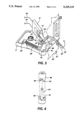
- FIG. 1 illustrates a conventional prior art switch.
- the switch consists of a base substrate 2, which may be of a lightweight plastic construction, to which are mounted a horseshoe sensor 4 and a rotary switch assembly 6.
- Sensor 4 has a bifurcated or horseshoe configuration to establish upper and lower legs 8, 10, respectively.
- Upper leg 8 supports a light source such as a light emitting diode (LED) 12, where the lower leg 10 supports a light detector such as a photodiode 14.
- the diodes 12, 14 are aligned on a common sensing axis 16.
- Switch 6 which may be made from a one piece molded plastic, comprises a hub 22 which is seated on a metal pivot post 24. Post 24 is rigidly connected to substrate 2. A curled hook segment 26 forms an extension of the hub and is used as the connection for one end of biasing spring 28. The other end of spring 28 is connected to a protrusion 30 which extends vertically upward from substrate 2. Switch 6 further comprises two arms 32, 34. Arm 32 is an arcuate shape and terminates in a tip 33 which projects an inclined edge surface 35 into the path of a paper sheet 36, moving in the direction of arrow 37.
- Arm 34 is generally oriented in the opposite direction and is positioned in its non-operative state so that the tip of arm 34 lies within the common sensing axis 16 between LED 12 and diode 14. In this position, the light from LED 12 is prevented from reaching diode 14; hence, there is no output signal on connection 20.
- the present invention relates to a rotary switch actuator comprising:
- an actuator arm pivotably mounted to a substrate for movement between a reset position and a switch activated position
- a hub member mounted for rotation on a pivot member fixed in position on said substrate, the improvement wherein the bottom surface of said hub member has at least two inclined surface segments which mate with inclined surfaces protruding upward from the substrate.
- FIG. 1 shows a prior art, rotary switch in a sheet transport path.
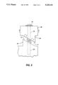
- FIG. 2 is an exploded view of the hub portion of the rotary switch shown in FIG. 1.
- FIG. 3 shows a rotary switch of the present invention in a paper transport path.
- FIG. 4 shows an exploded view of the hub portion of the switch shown in FIG. 3.
- FIG. 5 shows a side view demonstrating the side view of the switch of FIGS. 3 and 4 demonstrating the bias forces operating on the hub mounting surface.
- FIG. 3 there is shown an improved rotary switch actuator of the present invention.
- the switch construction and the base substrate elements are similar to the prior art switch of FIG. 1 and the components whose functions do not change are identified by the same call outs with a prime (').
- the changes in construction are found in the lower half of the hub member and in the configuration of the mounting (seating) protrusions or teeth formed on substrate 2.
- the modified configuration results in elimination of the "bounce back" phenomena and is best illustrated by referring to the exploded view of the hub member 48 and seating elements 50, 52, 62, 64, shown in FIG. 4.
- FIGS. 3 and 4 the arcuate rectangular teeth-like member of the prior art (teeth 40, 42 of FIG.
- Hub member 48 also has two arcuate downwardly extending, helically-shaped teeths 62, 64 separated by 180°. When hub member 48 is fully seated, the body of hub member 48, or rather the bottom surface of teeth 62, 64 are supported along the top surface of teeth 50, 52.
- switch 6' The mechanical operation of switch 6' is the same as that described for switch 6.
- Paper sheet 36 creates the force which rotates the switch CCW and extends spring 28 storing a return force F.
- hub 48 rotates, moving teeth 62, 64 away from the seated position on the surfaces of teeth 50, 52 and into spaces D.
- the spring energy force F
- the helical surfaces of teeth 62, 64 are brought into gradual contact and mate with the helical surfaces of teeth 50, 52 in such a way as to translate the spring force in a direction normal to the mating surfaces of teeth 62, 64 and 50, 52.
Landscapes
- Rotary Switch, Piano Key Switch, And Lever Switch (AREA)
Abstract
Description
Claims (4)
Priority Applications (1)
| Application Number | Priority Date | Filing Date | Title |
|---|---|---|---|
| US08/051,712 US5329119A (en) | 1993-04-23 | 1993-04-23 | Rotary switch actuator for detecting the presence of a sheet or the like with a hub member having inclined surface segments |
Applications Claiming Priority (1)
| Application Number | Priority Date | Filing Date | Title |
|---|---|---|---|
| US08/051,712 US5329119A (en) | 1993-04-23 | 1993-04-23 | Rotary switch actuator for detecting the presence of a sheet or the like with a hub member having inclined surface segments |
Publications (1)
| Publication Number | Publication Date |
|---|---|
| US5329119A true US5329119A (en) | 1994-07-12 |
Family
ID=21972918
Family Applications (1)
| Application Number | Title | Priority Date | Filing Date |
|---|---|---|---|
| US08/051,712 Expired - Lifetime US5329119A (en) | 1993-04-23 | 1993-04-23 | Rotary switch actuator for detecting the presence of a sheet or the like with a hub member having inclined surface segments |
Country Status (1)
| Country | Link |
|---|---|
| US (1) | US5329119A (en) |
Cited By (9)
| Publication number | Priority date | Publication date | Assignee | Title |
|---|---|---|---|---|
| EP0837019A1 (en) * | 1996-10-09 | 1998-04-22 | Sharp Kabushiki Kaisha | A detecting device for detecting the traveling state of a moving object |
| EP0900754A1 (en) * | 1997-09-02 | 1999-03-10 | Hewlett-Packard Company | An optical device for detecting the printing media in printers |
| US6080943A (en) * | 1999-08-02 | 2000-06-27 | France/Scott Fetzer Company | Timer |
| WO2002038898A1 (en) * | 2000-11-07 | 2002-05-16 | Siemens Aktiengesellschaft | Soft stop mechanism and method |
| US6583371B1 (en) | 2001-11-02 | 2003-06-24 | France/Scott Fetzer Company | Timer |
| US6613991B1 (en) | 1999-08-02 | 2003-09-02 | France/Scott Fetzer Company | Timer |
| US20040090871A1 (en) * | 1999-08-02 | 2004-05-13 | France/Scott Fetzer Company | Timer |
| CN102649515A (en) * | 2011-02-25 | 2012-08-29 | 佳能株式会社 | Sheet detecting apparatus and image forming apparatus |
| US20150102551A1 (en) * | 2013-10-15 | 2015-04-16 | Canon Kabushiki Kaisha | Detection apparatus and image forming apparatus |
Citations (3)
| Publication number | Priority date | Publication date | Assignee | Title |
|---|---|---|---|---|
| US4695683A (en) * | 1986-07-23 | 1987-09-22 | Telechron, Inc. | Electric appliance timer with automatic turn off |
| US5042790A (en) * | 1990-02-16 | 1991-08-27 | Xerox Corporation | Toggled switch for use in a sheet feed apparatus |
| US5063364A (en) * | 1990-04-12 | 1991-11-05 | Com Dev Ltd. | C-, t- and s-switches that are mechanically operated by a rotary actuator |
-
1993
- 1993-04-23 US US08/051,712 patent/US5329119A/en not_active Expired - Lifetime
Patent Citations (3)
| Publication number | Priority date | Publication date | Assignee | Title |
|---|---|---|---|---|
| US4695683A (en) * | 1986-07-23 | 1987-09-22 | Telechron, Inc. | Electric appliance timer with automatic turn off |
| US5042790A (en) * | 1990-02-16 | 1991-08-27 | Xerox Corporation | Toggled switch for use in a sheet feed apparatus |
| US5063364A (en) * | 1990-04-12 | 1991-11-05 | Com Dev Ltd. | C-, t- and s-switches that are mechanically operated by a rotary actuator |
Cited By (17)
| Publication number | Priority date | Publication date | Assignee | Title |
|---|---|---|---|---|
| US5923140A (en) * | 1996-10-09 | 1999-07-13 | Sharp Kabushiki Kaisha | Detecting device for detecting the traveling state of a moving object |
| EP0837019A1 (en) * | 1996-10-09 | 1998-04-22 | Sharp Kabushiki Kaisha | A detecting device for detecting the traveling state of a moving object |
| US6152443A (en) * | 1997-09-02 | 2000-11-28 | Hewlett-Packard Company | Optical device for detecting the printing media in printers |
| EP0900754A1 (en) * | 1997-09-02 | 1999-03-10 | Hewlett-Packard Company | An optical device for detecting the printing media in printers |
| US6613991B1 (en) | 1999-08-02 | 2003-09-02 | France/Scott Fetzer Company | Timer |
| US6080943A (en) * | 1999-08-02 | 2000-06-27 | France/Scott Fetzer Company | Timer |
| US20040079624A1 (en) * | 1999-08-02 | 2004-04-29 | France/Scott Fetzer Company | Timer |
| US20040090871A1 (en) * | 1999-08-02 | 2004-05-13 | France/Scott Fetzer Company | Timer |
| US6797897B2 (en) | 1999-08-02 | 2004-09-28 | France/Scott Fetzer Company | Timer |
| US6838628B2 (en) | 1999-08-02 | 2005-01-04 | France/Scott Fetzer Company | Timer |
| WO2002038898A1 (en) * | 2000-11-07 | 2002-05-16 | Siemens Aktiengesellschaft | Soft stop mechanism and method |
| US6431340B1 (en) | 2000-11-07 | 2002-08-13 | Siemens Vdo Automotive Corporation | Soft stop mechanism and method |
| US6583371B1 (en) | 2001-11-02 | 2003-06-24 | France/Scott Fetzer Company | Timer |
| CN102649515A (en) * | 2011-02-25 | 2012-08-29 | 佳能株式会社 | Sheet detecting apparatus and image forming apparatus |
| CN102649515B (en) * | 2011-02-25 | 2014-11-19 | 佳能株式会社 | Sheet detecting apparatus and image forming apparatus |
| US20150102551A1 (en) * | 2013-10-15 | 2015-04-16 | Canon Kabushiki Kaisha | Detection apparatus and image forming apparatus |
| US9254976B2 (en) * | 2013-10-15 | 2016-02-09 | Canon Kabushiki Kaisha | Detection apparatus and image forming apparatus |
Similar Documents
| Publication | Publication Date | Title |
|---|---|---|
| US5329119A (en) | Rotary switch actuator for detecting the presence of a sheet or the like with a hub member having inclined surface segments | |
| US7292741B2 (en) | Multi-input optical switch | |
| US6259433B1 (en) | Digital optical joystick with mechanically magnified resolution | |
| CA2210118C (en) | Joystick device | |
| GB2283811A (en) | Encoder | |
| US5453732A (en) | Shift lever position sensor | |
| KR930006769A (en) | Limit switch | |
| US4739315A (en) | X-Y input device | |
| JPH02212182A (en) | Printer with mechanism for detecting paper delivery and zoro row | |
| US4831253A (en) | Rotary type photoelectric switch | |
| KR900000870A (en) | Non-contact rotary mode switch device of magnetic tape recording device | |
| EP1024238A3 (en) | Device for detecting the position of a lock bolt | |
| US4223193A (en) | Device for representing status of push button switch | |
| JP3037379U (en) | Button switch | |
| US6767271B2 (en) | Sensor switch assembly | |
| JPS57195203A (en) | Optical switch | |
| ATE140338T1 (en) | LIMIT SWITCH | |
| US3621166A (en) | Air impulse electrical switch with alternate action | |
| JPH0326589Y2 (en) | ||
| JPH0687378U (en) | Elevator push button | |
| KR900003842A (en) | Automatic stop mechanism of tape recorder | |
| JPH0530788Y2 (en) | ||
| KR0145757B1 (en) | Body tilt detection device when cornering a car | |
| JPS62834Y2 (en) | ||
| KR100449020B1 (en) | Paper detecting apparatus for printer |
Legal Events
| Date | Code | Title | Description |
|---|---|---|---|
| AS | Assignment |
Owner name: XEROX CORPORATION, CONNECTICUT Free format text: ASSIGNMENT OF ASSIGNORS INTEREST;ASSIGNORS:SWARTZ, CRAIG R.;MILESKI, RAYMOND P.;HAVRANEK, JOHN L.;REEL/FRAME:006542/0139;SIGNING DATES FROM 19930415 TO 19930416 |
|
| STPP | Information on status: patent application and granting procedure in general |
Free format text: APPLICATION UNDERGOING PREEXAM PROCESSING |
|
| FPAY | Fee payment |
Year of fee payment: 4 |
|
| FPAY | Fee payment |
Year of fee payment: 8 |
|
| AS | Assignment |
Owner name: BANK ONE, NA, AS ADMINISTRATIVE AGENT, ILLINOIS Free format text: SECURITY INTEREST;ASSIGNOR:XEROX CORPORATION;REEL/FRAME:013153/0001 Effective date: 20020621 |
|
| AS | Assignment |
Owner name: JPMORGAN CHASE BANK, AS COLLATERAL AGENT, TEXAS Free format text: SECURITY AGREEMENT;ASSIGNOR:XEROX CORPORATION;REEL/FRAME:015134/0476 Effective date: 20030625 Owner name: JPMORGAN CHASE BANK, AS COLLATERAL AGENT,TEXAS Free format text: SECURITY AGREEMENT;ASSIGNOR:XEROX CORPORATION;REEL/FRAME:015134/0476 Effective date: 20030625 |
|
| FPAY | Fee payment |
Year of fee payment: 12 |
|
| AS | Assignment |
Owner name: XEROX CORPORATION, CONNECTICUT Free format text: RELEASE BY SECURED PARTY;ASSIGNOR:JPMORGAN CHASE BANK, N.A. AS SUCCESSOR-IN-INTEREST ADMINISTRATIVE AGENT AND COLLATERAL AGENT TO JPMORGAN CHASE BANK;REEL/FRAME:066728/0193 Effective date: 20220822 |